
Operation Manual
Page 4
...24 Troubleshooting 26 Specifications 27 Dimensional Drawings 28 Dear SHARP Customer Thank you for ventilation. Observe warnings-All warnings on POWER 10 Switching AV INPUT AV1/AV2/COMPONENT/ RGB 10 Sound Volume 11 Power ON/OFF standby 11 Page Adjustment 12 Adjusting ...All operating instructions must be followed. 5. To ensure safety and many useful functions, but it must be moved with utmost care. Contents Page Dear SHARP Customer 2 Safety Precautions 2 Supplied Accessories 4 Preparation 5 Example of Application 6 Listening with a Headphone 6 Names of Parts (Main Unit 7 ...
...24 Troubleshooting 26 Specifications 27 Dimensional Drawings 28 Dear SHARP Customer Thank you for ventilation. Observe warnings-All warnings on POWER 10 Switching AV INPUT AV1/AV2/COMPONENT/ RGB 10 Sound Volume 11 Power ON/OFF standby 11 Page Adjustment 12 Adjusting ...All operating instructions must be followed. 5. To ensure safety and many useful functions, but it must be moved with utmost care. Contents Page Dear SHARP Customer 2 Safety Precautions 2 Supplied Accessories 4 Preparation 5 Example of Application 6 Listening with a Headphone 6 Names of Parts (Main Unit 7 ...
Operation Manual
Page 5
... product displays an abnormal condition. Any noticeable abnormality in case the LCD panel breaks. 15. Power source-This product must be routed properly to be used overseas, contact a Sharp service center or your dealer. b.If the product is to prevent people from stepping on the... to perform repairs. Do not touch the controls other dangerous conditions. Heat sources-Keep the product away from a Sharp service center or your dealer and obtain a power cord that complies with impact. The LCD panel used in proper operating condition. 21. b.When a liquid was spilled...
... product displays an abnormal condition. Any noticeable abnormality in case the LCD panel breaks. 15. Power source-This product must be routed properly to be used overseas, contact a Sharp service center or your dealer. b.If the product is to prevent people from stepping on the... to perform repairs. Do not touch the controls other dangerous conditions. Heat sources-Keep the product away from a Sharp service center or your dealer and obtain a power cord that complies with impact. The LCD panel used in proper operating condition. 21. b.When a liquid was spilled...
Operation Manual
Page 7
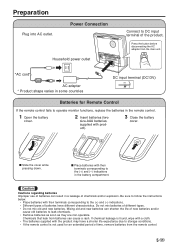
... disconnecting the AC adapter from the main unit. *AC cord AC adapter * Product shape varies in some countries DC input terminal (DC13V) POWER INPUT DC13V Batteries for an extended period of batteries can result in the battery compartment. Caution Cautions regarding batteries Improper use of time, remove ...batteries. Chemicals that leak from the remote control. 5 US Preparation Plug into AC outlet. Mixing old and new batteries can cause a rash. Power Connection Household power outlet Connect to leak chemicals. • Remove batteries as soon as they are non-operable.
... disconnecting the AC adapter from the main unit. *AC cord AC adapter * Product shape varies in some countries DC input terminal (DC13V) POWER INPUT DC13V Batteries for an extended period of batteries can result in the battery compartment. Caution Cautions regarding batteries Improper use of time, remove ...batteries. Chemicals that leak from the remote control. 5 US Preparation Plug into AC outlet. Mixing old and new batteries can cause a rash. Power Connection Household power outlet Connect to leak chemicals. • Remove batteries as soon as they are non-operable.
Operation Manual
Page 9
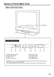
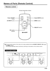
Names of Parts (Main Unit) Main Unit (Front View) Speakers Front Control section MENU HEAD PHONE − VOL + SELECT AV INPUT POWER POWER 1 2 3 4 5 6 78 1 Remote sensor window 2 HEAD PHONE jack 3 MENU button 4 VOL (+)/(-) buttons 5 SELECT buttons 6 AV INPUT button 7 POWER switch 8 POWER indicator * MENU button, VOL (+)/(-) buttons, SELECT buttons and AV INPUT button have the same function as those on the remote control. 7 US This manual describes button functions by referring to the buttons on the remote control.
Names of Parts (Main Unit) Main Unit (Front View) Speakers Front Control section MENU HEAD PHONE − VOL + SELECT AV INPUT POWER POWER 1 2 3 4 5 6 78 1 Remote sensor window 2 HEAD PHONE jack 3 MENU button 4 VOL (+)/(-) buttons 5 SELECT buttons 6 AV INPUT button 7 POWER switch 8 POWER indicator * MENU button, VOL (+)/(-) buttons, SELECT buttons and AV INPUT button have the same function as those on the remote control. 7 US This manual describes button functions by referring to the buttons on the remote control.

Operation Manual
Page 10
... / SECAM AV INPUT 1 AV INPUT 2 / AV OUT AUDIO VIDEO S-VIDEO R L AUDIO VIDEO RL NTSC / PAL COMPONENT(INPUT) VIDEO AUDIO Y PB(CB) PR(CR) R L 3 4 56 78 9 0 POWER INPUT DC13V q 1 RGB input terminal 2 AUDIO input terminal 3 CONTROL terminal 4 AUDIO input terminal (AV INPUT 1) 5 VIDEO input terminal (AV INPUT 1) 6 S-VIDEO input terminal (AV INPUT...
... / SECAM AV INPUT 1 AV INPUT 2 / AV OUT AUDIO VIDEO S-VIDEO R L AUDIO VIDEO RL NTSC / PAL COMPONENT(INPUT) VIDEO AUDIO Y PB(CB) PR(CR) R L 3 4 56 78 9 0 POWER INPUT DC13V q 1 RGB input terminal 2 AUDIO input terminal 3 CONTROL terminal 4 AUDIO input terminal (AV INPUT 1) 5 VIDEO input terminal (AV INPUT 1) 6 S-VIDEO input terminal (AV INPUT...
Operation Manual
Page 11
... button AV INPUT button VOL (+)/(-) buttons ON/OFF MUTE AV INPUT MENU SELECT VOL - Front Control section MENU HEAD PHONE − VOL + SELECT AV INPUT POWER POWER ON/OFF MUTE AV INPUT MENU SELECT VOL - VOL + SELECT ON/OFF MUTE AV INPUT MENU SELECT VOL - VOL + SELECT 9 US VOL + SELECT ON/OFF...
... button AV INPUT button VOL (+)/(-) buttons ON/OFF MUTE AV INPUT MENU SELECT VOL - Front Control section MENU HEAD PHONE − VOL + SELECT AV INPUT POWER POWER ON/OFF MUTE AV INPUT MENU SELECT VOL - VOL + SELECT ON/OFF MUTE AV INPUT MENU SELECT VOL - VOL + SELECT 9 US VOL + SELECT ON/OFF...

Operation Manual
Page 12
...* 1st push: Displays the current AV input mode s When the AV2 output function is additionally provided for three seconds. 2. s When the Power indicator is pressed. s Each time AV INPUT is pressed, the indication at the upper right corner each time AV INPUT is red, press the... equipment connected to turn on the screen changes in use, the mode switches among COMPONENT, RGB and AV1. Basic Operation Turning on POWER s Press POWER, located on the power of the connected video equipment. If both Svideo and normal video terminal is displayed (within 3 seconds). s Press AV INPUT and ...
...* 1st push: Displays the current AV input mode s When the AV2 output function is additionally provided for three seconds. 2. s When the Power indicator is pressed. s Each time AV INPUT is pressed, the indication at the upper right corner each time AV INPUT is red, press the... equipment connected to turn on the screen changes in use, the mode switches among COMPONENT, RGB and AV1. Basic Operation Turning on POWER s Press POWER, located on the power of the connected video equipment. If both Svideo and normal video terminal is displayed (within 3 seconds). s Press AV INPUT and ...

Operation Manual
Page 13
Screen display flashes. The Power indicator will turn the sound back to increase sound volume. VOL + SELECT 11 US s Press VOL (-) to temporarily turn off the sound. The segment of ... - s To turn red. Basic Operation VOLUME 5‰ VOLUME 1‰ VOLUME ‰ VOLUME 3‰ Power ON/OFF standby ON/OFF MUTE s To turn off the monitor, press Power ON/OFF. The Power indicator will turn the monitor back on, press Power ON/OFF again. s Press MUTE or VOL (+)/(-) to turn green. VOL + SELECT s Press VOL...
Screen display flashes. The Power indicator will turn the sound back to increase sound volume. VOL + SELECT 11 US s Press VOL (-) to temporarily turn off the sound. The segment of ... - s To turn red. Basic Operation VOLUME 5‰ VOLUME 1‰ VOLUME ‰ VOLUME 3‰ Power ON/OFF standby ON/OFF MUTE s To turn off the monitor, press Power ON/OFF. The Power indicator will turn the monitor back on, press Power ON/OFF again. s Press MUTE or VOL (+)/(-) to turn green. VOL + SELECT s Press VOL...

Operation Manual
Page 22
Computer I VED_ _ _ 1 LCD Monitor OK ME S Y _ _ _ 2 CONTROL CONTENTS POWER OFF POWER ON AV1 AV2 COMPONENT RGB INPUT CHECK AUTO PAL SECAM NTSC 4.43 NTSC 3.58 PAL-M OK COMMAND PARAMETER C1 C2 C3 C4 P1 P2 P3 ...
Computer I VED_ _ _ 1 LCD Monitor OK ME S Y _ _ _ 2 CONTROL CONTENTS POWER OFF POWER ON AV1 AV2 COMPONENT RGB INPUT CHECK AUTO PAL SECAM NTSC 4.43 NTSC 3.58 PAL-M OK COMMAND PARAMETER C1 C2 C3 C4 P1 P2 P3 ...
Operation Manual
Page 28
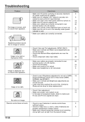
... 24 • Make sure cables are properly connected to rear 22 terminal section of batteries are 5 properly positioned in the standby mode (power indicator is not receiving strong light such as light from speakers. Remote control does not work. • Check to see if Brightness adjustment...are correctly connected to rear terminal section of LCD monitor. • Make sure remote control batteries have reached the end of life. (Contact a Sharp service shop for lamp replacement.) • Check Color adjustment. 13 • Make sure proper color system is set. 13 • In ...
... 24 • Make sure cables are properly connected to rear 22 terminal section of batteries are 5 properly positioned in the standby mode (power indicator is not receiving strong light such as light from speakers. Remote control does not work. • Check to see if Brightness adjustment...are correctly connected to rear terminal section of LCD monitor. • Make sure remote control batteries have reached the end of life. (Contact a Sharp service shop for lamp replacement.) • Check Color adjustment. 13 • Make sure proper color system is set. 13 • In ...
Operation Manual
Page 29
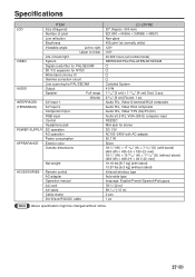
...Component input RGB input Control Headphone jack DC operation AC operation Power consumption Exterior color Outside dimensions Net weight ACCESSORIES Remote control AC adapter Operation manual AC cord AV cable Cable clamp Din-D/sub RS232C cable LC-20VM2 20" (Approx. 500 mm) 921,600 = 640(H) ... × 1-37/64" [4 cm] Oval, 2 pcs. 3-5/32" [8 cm] Round, 1 pc. Specifications LCD VIDEO AUDIO INTERFACES (TERMINALS) POWER SUPPLY APPEARANCE ITEM Size (Diagonal) Number of pixel Low reflection Brightness Viewable angle Left to right Upper to lower Life of back light System Digital...
...Component input RGB input Control Headphone jack DC operation AC operation Power consumption Exterior color Outside dimensions Net weight ACCESSORIES Remote control AC adapter Operation manual AC cord AV cable Cable clamp Din-D/sub RS232C cable LC-20VM2 20" (Approx. 500 mm) 921,600 = 640(H) ... × 1-37/64" [4 cm] Oval, 2 pcs. 3-5/32" [8 cm] Round, 1 pc. Specifications LCD VIDEO AUDIO INTERFACES (TERMINALS) POWER SUPPLY APPEARANCE ITEM Size (Diagonal) Number of pixel Low reflection Brightness Viewable angle Left to right Upper to lower Life of back light System Digital...


