

Operation Manual
Page 2
... the following measures: • Relocate or adjust the receiving antenna. • Increase the separation between the equipment and receiver. • Connect the equipment into an outlet on a circuit different from that may cause harmful interference to operate this equipment not expressly approved by turning the equipment off and on, the user is connected. • Consult the dealer or an...
... the following measures: • Relocate or adjust the receiving antenna. • Increase the separation between the equipment and receiver. • Connect the equipment into an outlet on a circuit different from that may cause harmful interference to operate this equipment not expressly approved by turning the equipment off and on, the user is connected. • Consult the dealer or an...
Operation Manual
Page 4
... (Rear View 8 Names of Parts (Remote Control 9 Remote control 9 Basic Operation 10 Turning on POWER 10 Switching AV INPUT AV1/AV2/COMPONENT/ RGB 10 Sound Volume 11 Power ON/OFF standby 11 Page Adjustment 12 Adjusting the PICTURE settings 12 Adjusting the SOUND settings 14 Adjusting the PRESET settings 15 Adjusting the FINE SYNC Settings (RGB mode only 16 Connecting to computer 17 Connection Pin Assignments 18 RGB Input Signals (Recommended Timing) ........ 18 RS232C terminal specifications 19 Connecting to Video Equipment 22 Watching TV 22 Connecting with VIDEO Equipment...
... (Rear View 8 Names of Parts (Remote Control 9 Remote control 9 Basic Operation 10 Turning on POWER 10 Switching AV INPUT AV1/AV2/COMPONENT/ RGB 10 Sound Volume 11 Power ON/OFF standby 11 Page Adjustment 12 Adjusting the PICTURE settings 12 Adjusting the SOUND settings 14 Adjusting the PRESET settings 15 Adjusting the FINE SYNC Settings (RGB mode only 16 Connecting to computer 17 Connection Pin Assignments 18 RGB Input Signals (Recommended Timing) ........ 18 RS232C terminal specifications 19 Connecting to Video Equipment 22 Watching TV 22 Connecting with VIDEO Equipment...
Operation Manual
Page 5
... case the LCD panel breaks. 15. Overloading-Do not overload AC outlets or extension cords. Entering of blue, green or red. Removing covers can break when the product is to the operating instructions. 12. c. d.When the product does not operate properly as a fixed point of objects and liquids-Never insert an object into the product. Replacement parts-In case the product needs replacement parts, make...
... case the LCD panel breaks. 15. Overloading-Do not overload AC outlets or extension cords. Entering of blue, green or red. Removing covers can break when the product is to the operating instructions. 12. c. d.When the product does not operate properly as a fixed point of objects and liquids-Never insert an object into the product. Replacement parts-In case the product needs replacement parts, make...
Operation Manual
Page 6
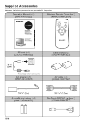
...) Din-D/sub RS232C cable (×1) (QCNW-5288CEZZ) US 4 Operation Manual (×1) (TINS-6901CEZZ) Wireless Remote Control (×1) (RRMCG1459CESA) LC-20VM2 LCD AV MONITOR MONITEUR AV À CRISTAUX LIQUIDES MONITOR AV LCD MONITOR AV DE TELA DE CRISTAL LÍQUIDO OPERATION MANUAL MODE D'EMPLOI MANUAL DE MANEJO MANUAL DE OPERAÇÃO ESPAÑOL FRANÇAIS ENGLISH ON/OFF MUTE AV INPUT MENU SELECT VOL - Supplied Accessories Make sure the...
...) Din-D/sub RS232C cable (×1) (QCNW-5288CEZZ) US 4 Operation Manual (×1) (TINS-6901CEZZ) Wireless Remote Control (×1) (RRMCG1459CESA) LC-20VM2 LCD AV MONITOR MONITEUR AV À CRISTAUX LIQUIDES MONITOR AV LCD MONITOR AV DE TELA DE CRISTAL LÍQUIDO OPERATION MANUAL MODE D'EMPLOI MANUAL DE MANEJO MANUAL DE OPERAÇÃO ESPAÑOL FRANÇAIS ENGLISH ON/OFF MUTE AV INPUT MENU SELECT VOL - Supplied Accessories Make sure the...
Operation Manual
Page 7
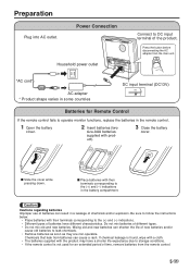
... (-) indications. • Different types of batteries can cause a rash. Press the button before disconnecting the AC adapter from batteries can result in the remote control. 1 Open the battery cover. 2 Insert batteries (two size-AAA batteries, supplied with their terminals corresponding to storage conditions. • If the remote control is not used for Remote Control If the remote control fails to operate monitor functions, replace the batteries in...
... (-) indications. • Different types of batteries can cause a rash. Press the button before disconnecting the AC adapter from batteries can result in the remote control. 1 Open the battery cover. 2 Insert batteries (two size-AAA batteries, supplied with their terminals corresponding to storage conditions. • If the remote control is not used for Remote Control If the remote control fails to operate monitor functions, replace the batteries in...
Operation Manual
Page 8
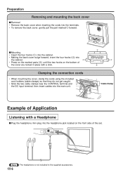
..., clamp the cords using the included cord holders (cable clamps) so that they do not get caught. • Stick the two cable clamps near the CONTROL terminal and the DC input terminal, then insert cables into the cabinet. 2 • Press on the marked parts (3) until the two hooks on the front side of the cover are locked in the supplied accessories. MENU - s Mounting •...
..., clamp the cords using the included cord holders (cable clamps) so that they do not get caught. • Stick the two cable clamps near the CONTROL terminal and the DC input terminal, then insert cables into the cabinet. 2 • Press on the marked parts (3) until the two hooks on the front side of the cover are locked in the supplied accessories. MENU - s Mounting •...
Operation Manual
Page 9
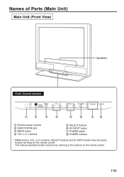
This manual describes button functions by referring to the buttons on the remote control. Names of Parts (Main Unit) Main Unit (Front View) Speakers Front Control section MENU HEAD PHONE − VOL + SELECT AV INPUT POWER POWER 1 2 3 4 5 6 78 1 Remote sensor window 2 HEAD PHONE jack 3 MENU button 4 VOL (+)/(-) buttons 5 SELECT buttons 6 AV INPUT button 7 POWER switch 8 POWER indicator * MENU button, VOL (+)/(-) buttons, SELECT buttons and AV INPUT button have the same function as those on the remote control. 7 US
This manual describes button functions by referring to the buttons on the remote control. Names of Parts (Main Unit) Main Unit (Front View) Speakers Front Control section MENU HEAD PHONE − VOL + SELECT AV INPUT POWER POWER 1 2 3 4 5 6 78 1 Remote sensor window 2 HEAD PHONE jack 3 MENU button 4 VOL (+)/(-) buttons 5 SELECT buttons 6 AV INPUT button 7 POWER switch 8 POWER indicator * MENU button, VOL (+)/(-) buttons, SELECT buttons and AV INPUT button have the same function as those on the remote control. 7 US

Operation Manual
Page 10
Names of Parts (Main Unit) Main Unit (Rear View) Rear Speaker (woofer) Rear terminal section AUDIO INPUT RGB INPUT (VGA60Hz) 1 2 CONTROL NTSC / PAL / SECAM AV INPUT 1 AV INPUT 2 / AV OUT AUDIO VIDEO S-VIDEO R L AUDIO VIDEO RL NTSC / PAL COMPONENT(INPUT) VIDEO AUDIO Y PB(CB) PR(CR) R L 3 4 56 78 9 0 POWER INPUT DC13V q 1 RGB input terminal 2 AUDIO input terminal 3 CONTROL terminal 4 AUDIO input terminal (AV INPUT 1) 5 VIDEO input terminal (AV INPUT 1) 6 S-VIDEO input terminal (AV INPUT 1) 7 AUDIO input terminal (AV INPUT 2/AV OUT) 8 VIDEO input terminal (AV INPUT 2/AV...
Names of Parts (Main Unit) Main Unit (Rear View) Rear Speaker (woofer) Rear terminal section AUDIO INPUT RGB INPUT (VGA60Hz) 1 2 CONTROL NTSC / PAL / SECAM AV INPUT 1 AV INPUT 2 / AV OUT AUDIO VIDEO S-VIDEO R L AUDIO VIDEO RL NTSC / PAL COMPONENT(INPUT) VIDEO AUDIO Y PB(CB) PR(CR) R L 3 4 56 78 9 0 POWER INPUT DC13V q 1 RGB input terminal 2 AUDIO input terminal 3 CONTROL terminal 4 AUDIO input terminal (AV INPUT 1) 5 VIDEO input terminal (AV INPUT 1) 6 S-VIDEO input terminal (AV INPUT 1) 7 AUDIO input terminal (AV INPUT 2/AV OUT) 8 VIDEO input terminal (AV INPUT 2/AV...

Operation Manual
Page 12
.... w Screen Initial mode (AV1) AV1 mode AV2 mode COMPONENT mode RGB mode AV INPUT AV1 PAL AV2 PAL COMPONENT RGB * 1st push: Displays the current AV input mode s When the AV2 output function is connected with cables, the S-video input terminal takes precedence. Basic Operation Turning on POWER s Press POWER, located on the power of the connected video equipment. tion disappears after three seconds. VOL + SELECT s Turn on the front side of the main unit. s Each time...
.... w Screen Initial mode (AV1) AV1 mode AV2 mode COMPONENT mode RGB mode AV INPUT AV1 PAL AV2 PAL COMPONENT RGB * 1st push: Displays the current AV input mode s When the AV2 output function is connected with cables, the S-video input terminal takes precedence. Basic Operation Turning on POWER s Press POWER, located on the power of the connected video equipment. tion disappears after three seconds. VOL + SELECT s Turn on the front side of the main unit. s Each time...
Operation Manual
Page 14
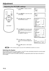
...;] BLACK LEVEL [ ‰] SHARPNESS [ ‰] RED [ ‰] BLUE [ ‰] COLOR SYSTEM [ AUTO] RESET SELECT: • ENTER :( • ) EXIT: MENU 5 Press VOL (+)/(-) to an appropriate system may improve the picture or sound quality. Adjustment Adjusting the PICTURE settings 1 Press MENU to display the PICTURE Menu screen. All of the set. VOL + SELECT 3 Press VOL (+)/(-) to display the Menu screen. The AUTO mode automatically detects the receiving signal system and changes the reception system of adjustment item is not stable, switching...
...;] BLACK LEVEL [ ‰] SHARPNESS [ ‰] RED [ ‰] BLUE [ ‰] COLOR SYSTEM [ AUTO] RESET SELECT: • ENTER :( • ) EXIT: MENU 5 Press VOL (+)/(-) to an appropriate system may improve the picture or sound quality. Adjustment Adjusting the PICTURE settings 1 Press MENU to display the PICTURE Menu screen. All of the set. VOL + SELECT 3 Press VOL (+)/(-) to display the Menu screen. The AUTO mode automatically detects the receiving signal system and changes the reception system of adjustment item is not stable, switching...
Operation Manual
Page 15
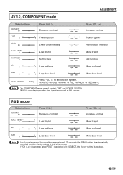
... green COLOR 3‰ Lower color intensity Higher color intensity BLACK LEVEL - ‰ SHARPNESS - ‰ RED - ‰ + Less bright + Soft picture + Less red level - + More bright - + Hard picture - + More red level BLUE - ‰ + Less blue level - + More blue level COLOR SYSTEM [ AUTO] Press VOL (+) to the initial screen. If VOL (+)/(-) is pressed after RESET is selected with SELECT, the factory setting is received in PAL system. PAL60 is also displayed when...
... green COLOR 3‰ Lower color intensity Higher color intensity BLACK LEVEL - ‰ SHARPNESS - ‰ RED - ‰ + Less bright + Soft picture + Less red level - + More bright - + Hard picture - + More red level BLUE - ‰ + Less blue level - + More blue level COLOR SYSTEM [ AUTO] Press VOL (+) to the initial screen. If VOL (+)/(-) is pressed after RESET is selected with SELECT, the factory setting is received in PAL system. PAL60 is also displayed when...
Operation Manual
Page 16
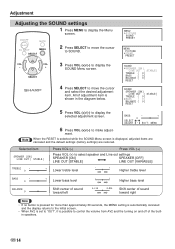
... the diagram below. ON/OFF MUTE AV INPUT MENU SELECT 2 Press SELECT to display the selected adjustment screen. BASS - + ‰ SELECT: • ADJUST:( • ) EXIT: MENU 6 Press VOL (+)/(-) to display the Menu screen. When the RESET is selected while the SOUND Menu screen is displayed, adjusted items are canceled and the default settings (factory settings) are restored. Adjustment Adjusting the SOUND settings 1 Press MENU to make adjust- SOUND SPEAKER [ON] LINE OUT [ STABLE] TREBLE [ ‰] BASS [ ‰] BALANCE [ ‰] RESET SOUND SPEAKER...
... the diagram below. ON/OFF MUTE AV INPUT MENU SELECT 2 Press SELECT to display the selected adjustment screen. BASS - + ‰ SELECT: • ADJUST:( • ) EXIT: MENU 6 Press VOL (+)/(-) to display the Menu screen. When the RESET is selected while the SOUND Menu screen is displayed, adjusted items are canceled and the default settings (factory settings) are restored. Adjustment Adjusting the SOUND settings 1 Press MENU to make adjust- SOUND SPEAKER [ON] LINE OUT [ STABLE] TREBLE [ ‰] BASS [ ‰] BALANCE [ ‰] RESET SOUND SPEAKER...

Operation Manual
Page 17
... display the Menu ON/OFF MUTE screen. The user can be set by using SELECT and VOL (+)/ (-) buttons. Adjustment MENU PICTURE SOUND PRESET MENU PICTURE SOUND PRESET PRESET BRIGHTNESS UPSIDE RIGHT/LEFT AV2 IN/OUT AV1 LINE SCREEN MODE [BRIGHT] [NORMAL] [NORMAL] [IN ] [NORMAL] [MODE 1] SELECT: • ENTER :( • ) EXIT: MENU 4 Check the factory setting of each item on the display for normal pictures. * The scan conversion modes work in input mode [OUT] AV input 2 changes to AV output mode → Video/audio signals...
... display the Menu ON/OFF MUTE screen. The user can be set by using SELECT and VOL (+)/ (-) buttons. Adjustment MENU PICTURE SOUND PRESET MENU PICTURE SOUND PRESET PRESET BRIGHTNESS UPSIDE RIGHT/LEFT AV2 IN/OUT AV1 LINE SCREEN MODE [BRIGHT] [NORMAL] [NORMAL] [IN ] [NORMAL] [MODE 1] SELECT: • ENTER :( • ) EXIT: MENU 4 Check the factory setting of each item on the display for normal pictures. * The scan conversion modes work in input mode [OUT] AV input 2 changes to AV output mode → Video/audio signals...

Operation Manual
Page 19
... AUDIO output terminal To RGB input terminal (commercially available) (commercially available) To RGB output terminal Note No RGB connection cable or PC audio cable is set. Handling of the RGB Connection Cable s Align the pins of this unit and those of personal computer. Computer IBM PC(DOS/V, PC/V, PC/AT) and compatible computers Display mode (Horizontal dots × Vertical lines) 640×480 Horizontal scanning...
... AUDIO output terminal To RGB input terminal (commercially available) (commercially available) To RGB output terminal Note No RGB connection cable or PC audio cable is set. Handling of the RGB Connection Cable s Align the pins of this unit and those of personal computer. Computer IBM PC(DOS/V, PC/V, PC/AT) and compatible computers Display mode (Horizontal dots × Vertical lines) 640×480 Horizontal scanning...
Operation Manual
Page 21
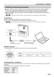
... LCD Monitor can be controlled from the computer via the RS232C terminal. s Attach an RS232C cable cross-type (commercially available) to match the LCD Monitor's communications conditions. RD SD - The input signal (computer/video) can be selected, the volume can be adjusted and various other adjustments and settings can be made, enabling automatic programed playing. Connecting to computer RS232C terminal specifications s When a program is accustomed to using the RS232C terminal. Connections Connect...
... LCD Monitor can be controlled from the computer via the RS232C terminal. s Attach an RS232C cable cross-type (commercially available) to match the LCD Monitor's communications conditions. RD SD - The input signal (computer/video) can be selected, the volume can be adjusted and various other adjustments and settings can be made, enabling automatic programed playing. Connecting to computer RS232C terminal specifications s When a program is accustomed to using the RS232C terminal. Connections Connect...

Operation Manual
Page 22
... after switching the display mode to the computer. If the LCD Monitor receives a command other than one code is being sent, send each adjustment menu and checking the status with the On-screen Display. Connecting to the computer. Note When using the computer control function of the LCD Monitor, the LCD Monitor operating status cannot be read to computer Communication procedure Send the control commands from the LCD Monitor is verified. Command format...
... after switching the display mode to the computer. If the LCD Monitor receives a command other than one code is being sent, send each adjustment menu and checking the status with the On-screen Display. Connecting to the computer. Note When using the computer control function of the LCD Monitor, the LCD Monitor operating status cannot be read to computer Communication procedure Send the control commands from the LCD Monitor is verified. Command format...
Operation Manual
Page 24
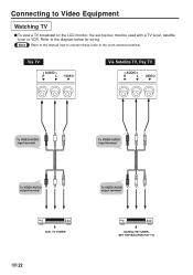
Note Refer to the manual how to connect these tuner to the diagram below for wiring. Refer to the room antenna terminal. Connecting to Video Equipment Watching TV s To view a TV broadcast on the LCD monitor, the set-top box must be used with a TV tuner, satellite tuner or VCR. Via TV AUDIO R L VIDEO Via Satellite TV, Pay TV AUDIO R L VIDEO To VIDEO/AUDIO input terminal To VIDEO/AUDIO input terminal To VIDEO/AUDIO output terminal To VIDEO/AUDIO output terminal VCR, TV TUNER US 22 SATELLITE TUNER, SET TOP BOX(FOR PAY TV)
Note Refer to the manual how to connect these tuner to the diagram below for wiring. Refer to the room antenna terminal. Connecting to Video Equipment Watching TV s To view a TV broadcast on the LCD monitor, the set-top box must be used with a TV tuner, satellite tuner or VCR. Via TV AUDIO R L VIDEO Via Satellite TV, Pay TV AUDIO R L VIDEO To VIDEO/AUDIO input terminal To VIDEO/AUDIO input terminal To VIDEO/AUDIO output terminal To VIDEO/AUDIO output terminal VCR, TV TUNER US 22 SATELLITE TUNER, SET TOP BOX(FOR PAY TV)

Operation Manual
Page 25
Connecting to Video Equipment Via Web TV, Game Unit AUDIO R L VIDEO S-VIDEO To VIDEO/AUDIO input terminal To VIDEO/AUDIO output terminal To S-VIDEO input terminal To S-VIDEO output terminal SET TOP BOX(WEB TV) GAME UNIT 23 US
Connecting to Video Equipment Via Web TV, Game Unit AUDIO R L VIDEO S-VIDEO To VIDEO/AUDIO input terminal To VIDEO/AUDIO output terminal To S-VIDEO input terminal To S-VIDEO output terminal SET TOP BOX(WEB TV) GAME UNIT 23 US
Operation Manual
Page 28
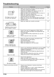
.... (Contact a Sharp service shop for lamp replacement.) • Check Color adjustment. 13 • Make sure proper color system is set . • Make sure cables are correctly connected to rear terminal section of LCD monitor. • Make sure remote control batteries have not worn out. • Make sure the unit is not in the standby mode (power indicator is red). • Make sure cables are correctly connected. US 26 Troubleshooting Problem No image...
.... (Contact a Sharp service shop for lamp replacement.) • Check Color adjustment. 13 • Make sure proper color system is set . • Make sure cables are correctly connected to rear terminal section of LCD monitor. • Make sure remote control batteries have not worn out. • Make sure the unit is not in the standby mode (power indicator is red). • Make sure cables are correctly connected. US 26 Troubleshooting Problem No image...
Operation Manual
Page 29
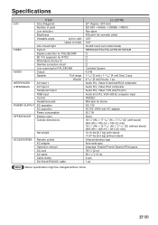
Audio R/L, Video S-terminal/RCA composite Audio R/L, Video RCA composite Audio R/L, Video Y/PB (CB)/PR (CR) Audio φ3.5 R/L VGA (60Hz) computer input RS232C Mini-jack for PAL/SECAM Output Speaker Full range Woofer AV input 1 AV input 2 Component input RGB input Control Headphone jack DC operation AC operation Power consumption Exterior color Outside dimensions Net weight ACCESSORIES Remote control AC adapter Operation manual AC cord AV cable Cable clamp Din-D/sub RS232C cable LC-20VM2 20" (Approx. 500 mm) 921,600 = 640(H) × 3(RGB) ×...
Audio R/L, Video S-terminal/RCA composite Audio R/L, Video RCA composite Audio R/L, Video Y/PB (CB)/PR (CR) Audio φ3.5 R/L VGA (60Hz) computer input RS232C Mini-jack for PAL/SECAM Output Speaker Full range Woofer AV input 1 AV input 2 Component input RGB input Control Headphone jack DC operation AC operation Power consumption Exterior color Outside dimensions Net weight ACCESSORIES Remote control AC adapter Operation manual AC cord AV cable Cable clamp Din-D/sub RS232C cable LC-20VM2 20" (Approx. 500 mm) 921,600 = 640(H) × 3(RGB) ×...


