
Service Manual
Page 1
SERVICE MANUAL DV-SL90UA SERVICE MANUAL S74X3DV-SL90U DVD VIDEO PLAYER The region number for SHARP CORPORATION after sales service only. 1 The contents are subject to those specified be used. DVD VIDEO PLAYER MODEL DV-SL90UA CONTENTS Page SPECIFICATIONS ...1-1-1 LASER BEAM SAFETY PRECAUTIONS 1-2-1 IMPORTANT SAFEGUARDS AND PRECAUTIONS 1-3-1 STANDARD NOTES FOR SERVICING 1-4-1 OPERATING CONTROLS AND FUNCTIONS 1-5-1 CABINET DISASSEMBLY INSTRUCTIONS 1-6-1 FIRMWARE RENEWAL MODE (FIRMWARE VERSION UP 1-7-1 TROUBLESHOOTING ...1-8-1 BLOCK DIAGRAMS ...1-9-1 SCHEMATIC DIAGRAMS/ CBA'S AND ...
SERVICE MANUAL DV-SL90UA SERVICE MANUAL S74X3DV-SL90U DVD VIDEO PLAYER The region number for SHARP CORPORATION after sales service only. 1 The contents are subject to those specified be used. DVD VIDEO PLAYER MODEL DV-SL90UA CONTENTS Page SPECIFICATIONS ...1-1-1 LASER BEAM SAFETY PRECAUTIONS 1-2-1 IMPORTANT SAFEGUARDS AND PRECAUTIONS 1-3-1 STANDARD NOTES FOR SERVICING 1-4-1 OPERATING CONTROLS AND FUNCTIONS 1-5-1 CABINET DISASSEMBLY INSTRUCTIONS 1-6-1 FIRMWARE RENEWAL MODE (FIRMWARE VERSION UP 1-7-1 TROUBLESHOOTING ...1-8-1 BLOCK DIAGRAMS ...1-9-1 SCHEMATIC DIAGRAMS/ CBA'S AND ...

Service Manual
Page 2
... X 51 mm X 211 mm NOTES: 1. Room ambient : 5 °C ~ 40 °C 500 2.0 120 ±0.5 ±0.5 0.0025 0.003 LIMIT ±0.1 1-1-1 E592BSP Load imp. : 100 k ohm 4. All Items are measured without pre-emphasis unless otherwise specified. 2. Power supply : AC 110 V - 240 V 50/60Hz 3. Response DVD CD 3-4. S/N 3-3. Output Level 3-2. SPECIFICATIONS ITEM 1 Video Output CONDITIONS 75 Ω UNIT Vpp NOMINAL 1.0 2 Coaxial Digital Out 3 Audio (PCM) 3-1.
... X 51 mm X 211 mm NOTES: 1. Room ambient : 5 °C ~ 40 °C 500 2.0 120 ±0.5 ±0.5 0.0025 0.003 LIMIT ±0.1 1-1-1 E592BSP Load imp. : 100 k ohm 4. All Items are measured without pre-emphasis unless otherwise specified. 2. Power supply : AC 110 V - 240 V 50/60Hz 3. Response DVD CD 3-4. S/N 3-3. Output Level 3-2. SPECIFICATIONS ITEM 1 Video Output CONDITIONS 75 Ω UNIT Vpp NOMINAL 1.0 2 Coaxial Digital Out 3 Audio (PCM) 3-1.

Service Manual
Page 3
... in hazardous radiation exposure. Drive Mecha Assembly Laser Beam Radiation Laser Pickup Turntable 1-2-1 DVD_LASER When checking the laser diode, be sure to strike against your eyes at the laser beam. Do not look directly at least 30cm away from... the pickup lens when the diode is emitted from the pickup or allow it to keep your skin. The laser beam is turned on. Caution: Use of controls and adjustments, or doing procedures other than those specified herein, may result in the figure. LASER BEAM SAFETY PRECAUTIONS This DVD player uses...
... in hazardous radiation exposure. Drive Mecha Assembly Laser Beam Radiation Laser Pickup Turntable 1-2-1 DVD_LASER When checking the laser diode, be sure to strike against your eyes at the laser beam. Do not look directly at least 30cm away from... the pickup lens when the diode is emitted from the pickup or allow it to keep your skin. The laser beam is turned on. Caution: Use of controls and adjustments, or doing procedures other than those specified herein, may result in the figure. LASER BEAM SAFETY PRECAUTIONS This DVD player uses...

Service Manual
Page 5
... wire solder by 40°C, and as it . Instructions for servicing Part No. When you may be exceeded, remove the bit from the PWB as soon as you are indicated as shown. < Bottom View > Pin 1 Using lead-free wire solder When fixing the PWB soldered with steel wool or fine sandpaper.... connect or disconnect the FFC (Flexible Foil Connector) cable, be apt to first disconnect the AC cord. 2. Lead-free wire solder for Connectors 1. As the melting point of the soldering bit, it with the lead-free solder, apply lead-free wire solder. Make sure to turn on the tip of lead-free ...
... wire solder by 40°C, and as it . Instructions for servicing Part No. When you may be exceeded, remove the bit from the PWB as soon as you are indicated as shown. < Bottom View > Pin 1 Using lead-free wire solder When fixing the PWB soldered with steel wool or fine sandpaper.... connect or disconnect the FFC (Flexible Foil Connector) cable, be apt to first disconnect the AC cord. 2. Lead-free wire solder for Connectors 1. As the melting point of the soldering bit, it with the lead-free solder, apply lead-free wire solder. Make sure to turn on the tip of lead-free ...
Service Manual
Page 9
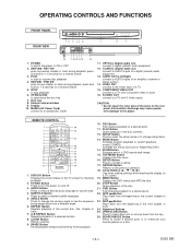
... to select a desired audio language or sound mode. 4. MENU Button Displays the DVD menus and MP3 file lists. 20. SKIP Button Plays back from the beginning of the current chapter or track. 23. Display 10. AUDIO Button Press to accept a setting. 17. A-B REPEAT Button Repeats playback of the disc. 21. SKIP / REV goes to turn the power on a TV screen. 19. press and hold for 1.5 seconds for a forward search 5. REMOTE CONTROL 1. STOP Button Stops operation of a selected section. 8. COAXIAL (Digital audio out) connect to a TV with S-Video inputs...
... to select a desired audio language or sound mode. 4. MENU Button Displays the DVD menus and MP3 file lists. 20. SKIP Button Plays back from the beginning of the current chapter or track. 23. Display 10. AUDIO Button Press to accept a setting. 17. A-B REPEAT Button Repeats playback of the disc. 21. SKIP / REV goes to turn the power on a TV screen. 19. press and hold for 1.5 seconds for a forward search 5. REMOTE CONTROL 1. STOP Button Stops operation of a selected section. 8. COAXIAL (Digital audio out) connect to a TV with S-Video inputs...

Service Manual
Page 10
... Plate [4] DVD Main CBA Unit [5] DVD Mecha [6] AV CBA [7] Function CBA 2. Disassembly Method ID/ LOC. of pickup will be serviced. Release four Locking Tabs (L-1). Bend, route, and dress the cables as a potential difference caused by electrostatic charge accumulated on cloth, human body etc., during unpacking or repair work. Then, release three Locking Tabs (L-2). 1-2. To avoid damage of the part 3 : Figure Number for...
... Plate [4] DVD Main CBA Unit [5] DVD Mecha [6] AV CBA [7] Function CBA 2. Disassembly Method ID/ LOC. of pickup will be serviced. Release four Locking Tabs (L-1). Bend, route, and dress the cables as a potential difference caused by electrostatic charge accumulated on cloth, human body etc., during unpacking or repair work. Then, release three Locking Tabs (L-2). 1-2. To avoid damage of the part 3 : Figure Number for...
Service Manual
Page 14
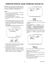
... models, "Disc Error" will appear on the remote control unit in Version Up Mode The DVD player can not read data which is described as follows: No. FIRMWARE RENEWAL MODE (FIRMWARE VERSION UP) FIRMWARE is built-in program to Joliet or ISO9660 (except ISO9660 LEVEL 1). Set the CD-ROM to update the FIRMWARE version. b appears on the screen. 1-7-1 E592BTEST a Version Up Mode Screen Fig. c is written with the tray open . 3. In this time...
... models, "Disc Error" will appear on the remote control unit in Version Up Mode The DVD player can not read data which is described as follows: No. FIRMWARE RENEWAL MODE (FIRMWARE VERSION UP) FIRMWARE is built-in program to Joliet or ISO9660 (except ISO9660 LEVEL 1). Set the CD-ROM to update the FIRMWARE version. b appears on the screen. 1-7-1 E592BTEST a Version Up Mode Screen Fig. c is written with the tray open . 3. In this time...
Service Manual
Page 15
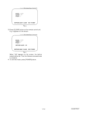
Then the firmware renewal mode is complete. 11.To exit this mode, press [POWER] button. 1-7-2 E592BTEST Fig. "*******" differ depending on the remote control unit. MODEL : ******* Version : *.** Region : * EEPROM CLEAR : OK EEPROM CLEAR : CLEAR EXIT: POWER Fig. g 10.Press [CLEAR] button on the models. h appears on the screen, the factory default will be set. h When "OK" appears on the screen. "*******" differ depending on the models. MODEL : ******* Version : *.** Region : * EEPROM CLEAR : CLEAR EXIT: POWER Fig.
Then the firmware renewal mode is complete. 11.To exit this mode, press [POWER] button. 1-7-2 E592BTEST Fig. "*******" differ depending on the remote control unit. MODEL : ******* Version : *.** Region : * EEPROM CLEAR : OK EEPROM CLEAR : CLEAR EXIT: POWER Fig. g 10.Press [CLEAR] button on the models. h appears on the screen, the factory default will be set. h When "OK" appears on the screen. "*******" differ depending on the models. MODEL : ******* Version : *.** Region : * EEPROM CLEAR : CLEAR EXIT: POWER Fig.

Service Manual
Page 16
... not operate normally. 18 Picture does not appear normally. 19 Audio is possible from the remote control unit. 14 The disc tray cannot be opened and closed. (It can be opened and closed. 16 [No Disc] indicated. 17 Both functions of Contents for the Troubleshooting Flow Charts Flow Chart No. Page 1-8-2 1-8-2 1-8-2 1-8-2 1-8-2 1-8-3 1-8-3 1-8-3 1-8-3 1-8-3 1-8-4 1-8-4 1-8-4 1-8-5 1-8-5 1-8-5 1-8-5 1-8-6 1-8-7 NOTE: CBA AND PWB MEANS PRINTED WIRING BOARD. 1-8-1 E592BTS Description 1 The power cannot be turned...
... not operate normally. 18 Picture does not appear normally. 19 Audio is possible from the remote control unit. 14 The disc tray cannot be opened and closed. (It can be opened and closed. 16 [No Disc] indicated. 17 Both functions of Contents for the Troubleshooting Flow Charts Flow Chart No. Page 1-8-2 1-8-2 1-8-2 1-8-2 1-8-2 1-8-3 1-8-3 1-8-3 1-8-3 1-8-3 1-8-4 1-8-4 1-8-4 1-8-5 1-8-5 1-8-5 1-8-5 1-8-6 1-8-7 NOTE: CBA AND PWB MEANS PRINTED WIRING BOARD. 1-8-1 E592BTS Description 1 The power cannot be turned...
Service Manual
Page 19
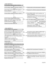
... 3PIN SW2101, 2105, 2108: IC2001 4PIN Yes Replace IC2001. Or replace the remote control unit. Yes Replace the fluorescent display tube. Check the EV+3.3V line and service it if defective. FLOW CHART NO.12 The key operation is possible from the remote control unit. Operation is possible from the DVD, but no operation is not functioning. Check D1016, D1017, T1001, and their periphery...
... 3PIN SW2101, 2105, 2108: IC2001 4PIN Yes Replace IC2001. Or replace the remote control unit. Yes Replace the fluorescent display tube. Check the EV+3.3V line and service it if defective. FLOW CHART NO.12 The key operation is possible from the remote control unit. Operation is possible from the DVD, but no operation is not functioning. Check D1016, D1017, T1001, and their periphery...

Service Manual
Page 20
... disc tray cannot be done using the remote control unit.) No Is the normal control voltage inputted to "FLOW CHART NO.15" Replace the "OPEN/CLOSE" button (SW2108). Yes Replace the DVD Mecha. Replace the DVD Main CBA. FLOW CHART NO.17 Both functions of IC2001? Yes Replace the DVD Mecha. No Original DVD Main CBA is poor. Refer to "FLOW CHART NO.12" Yes Refer to Pin(4) of picture...
... disc tray cannot be done using the remote control unit.) No Is the normal control voltage inputted to "FLOW CHART NO.15" Replace the "OPEN/CLOSE" button (SW2108). Yes Replace the DVD Mecha. Replace the DVD Main CBA. FLOW CHART NO.17 Both functions of IC2001? Yes Replace the DVD Mecha. No Original DVD Main CBA is poor. Refer to "FLOW CHART NO.12" Yes Refer to Pin(4) of picture...
Service Manual
Page 21
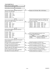
... signals outputted to No the VIDEO OUT terminal (JK1404)? Are the composite video signals outputted to the No S-VIDEO OUT terminal (JK1401)? No IC1402 3PIN Y IC1402 6PIN Cb/Pb IC1402 8PIN Cr/Pr IC1403 3PIN S-Y IC1403 1PIN S-C Yes Are the video signals outputted to the specific output ...of JK1404 from Pin (7) of IC1402 and service it if detective. Are the component video signals outputted to the pin(4, 12) of IC1402, pin(4) of IC1402, IC1403 on the disc tray, and playback. Replace the DVD Main CBA or DVD Mecha. CN1601 CN1601 CN1601 CN1601 CN1601 8PIN &#...
... signals outputted to No the VIDEO OUT terminal (JK1404)? Are the composite video signals outputted to the No S-VIDEO OUT terminal (JK1401)? No IC1402 3PIN Y IC1402 6PIN Cb/Pb IC1402 8PIN Cr/Pr IC1403 3PIN S-Y IC1403 1PIN S-C Yes Are the video signals outputted to the specific output ...of JK1404 from Pin (7) of IC1402 and service it if detective. Are the component video signals outputted to the pin(4, 12) of IC1402, pin(4) of IC1402, IC1403 on the disc tray, and playback. Replace the DVD Main CBA or DVD Mecha. CN1601 CN1601 CN1601 CN1601 CN1601 8PIN &#...
Service Manual
Page 22
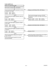
... the audio signals outputted to the specific No output terminal? Replace the DVD Main CBA or DVD Mecha. FLOW CHART NO.19 Audio is not outputted normally. Check each pin of IC1201 and JK1404, and service it if detective. Check the periphery between each pin of CN1601 and each line between Pins(1,7) of IC1201 on the disc tray, and playback. No Are the analog audio signals outputted...
... the audio signals outputted to the specific No output terminal? Replace the DVD Main CBA or DVD Mecha. FLOW CHART NO.19 Audio is not outputted normally. Check each pin of IC1201 and JK1404, and service it if detective. Check the periphery between each pin of CN1601 and each line between Pins(1,7) of IC1201 on the disc tray, and playback. No Are the analog audio signals outputted...

Service Manual
Page 23
...DIAGRAMS System Control / Servo Block Diagram NOTE: CBA AND PWB MEANS PRINTED WIRING BOARD. 1-9-1 TO VIDEO/ AUDIO BLOCK DIAGRAM PCM-SCLK A-MUTE ADAC-MD ADAC-MC ADAC-ML TO DIGITAL SIGNAL PROCESS BLOCK DIAGRAM FS(+) FS(-) TS(+) TS(-) +3.3V IC461 +3.3V IC462 2 RESET 1 1 RESET 3 IC301 (SERVO DRIVE) 15 FOCUS ACTUATOR 16 DRIVE +- 14 TRACKING ACTUATOR 13 DRIVE +- 12 SPINDLE MOTOR 11 DRIVE +- 17 SLED MOTOR 18 DRIVE...K2 2 K1 RM2001 REMOTE SENSOR WF16 WF14 WF13 WF15 CN2101 5 3 4 KEY 6 MATRIX 1 2 DRIVE CBA DVD MAIN CBA UNIT 66 TRAY-IN AV CBA FUNCTION CBA E592BBLS
...DIAGRAMS System Control / Servo Block Diagram NOTE: CBA AND PWB MEANS PRINTED WIRING BOARD. 1-9-1 TO VIDEO/ AUDIO BLOCK DIAGRAM PCM-SCLK A-MUTE ADAC-MD ADAC-MC ADAC-ML TO DIGITAL SIGNAL PROCESS BLOCK DIAGRAM FS(+) FS(-) TS(+) TS(-) +3.3V IC461 +3.3V IC462 2 RESET 1 1 RESET 3 IC301 (SERVO DRIVE) 15 FOCUS ACTUATOR 16 DRIVE +- 14 TRACKING ACTUATOR 13 DRIVE +- 12 SPINDLE MOTOR 11 DRIVE +- 17 SLED MOTOR 18 DRIVE...K2 2 K1 RM2001 REMOTE SENSOR WF16 WF14 WF13 WF15 CN2101 5 3 4 KEY 6 MATRIX 1 2 DRIVE CBA DVD MAIN CBA UNIT 66 TRAY-IN AV CBA FUNCTION CBA E592BBLS
Service Manual
Page 24
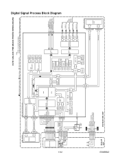
ROM DATA RAM INST. ROM SERIAL GENERAL I/O INTERRUPT CONTROLLER TIMER WATCH DOG TIMER REMOTE CONTROL AUDIO I/F VIDEO I/F BCU 32BIT CPU NTSC/PAL ENCODER SPDIF 177 PCM-BCK 170 PCM-DATA 171 PCM-LRCLK 169 TO VIDEO /AUDIO BLOCK DIAGRAM Y D/A 149 VIDEO-Y C D/A 158 VIDEO-C Cr/Pr VIDEO-Cr/Pr D/A 152 Cb/Pb VIDEO-Cb/Pb D/A 151 TO VIDEO /AUDIO BLOCK DIAGRAM D/A Y(I) 156 VIDEO-Y(I /O PROCESSOR DATA RAM INST. IC503 (SDRAM) SDRAM IC101 (MICRO CONTROLLER) ~~ 22 26 SDRAM...
ROM DATA RAM INST. ROM SERIAL GENERAL I/O INTERRUPT CONTROLLER TIMER WATCH DOG TIMER REMOTE CONTROL AUDIO I/F VIDEO I/F BCU 32BIT CPU NTSC/PAL ENCODER SPDIF 177 PCM-BCK 170 PCM-DATA 171 PCM-LRCLK 169 TO VIDEO /AUDIO BLOCK DIAGRAM Y D/A 149 VIDEO-Y C D/A 158 VIDEO-C Cr/Pr VIDEO-Cr/Pr D/A 152 Cb/Pb VIDEO-Cb/Pb D/A 151 TO VIDEO /AUDIO BLOCK DIAGRAM D/A Y(I) 156 VIDEO-Y(I /O PROCESSOR DATA RAM INST. IC503 (SDRAM) SDRAM IC101 (MICRO CONTROLLER) ~~ 22 26 SDRAM...
Service Manual
Page 27
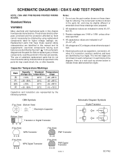
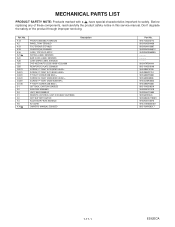
... and transistors are represented by using replacement components rated for higher voltage, wattage, etc. Before replacing any of substitute replacement parts that have special characteristics. All resistance values are identified by four digits. These characteristics often pass unnoticed...switches, and fuses are not shown for ordering. The use the part number shown on these special safety characteristics are indicated in ohms (K=103, M=106). 3. All capacitance values are identified in the parts list, and may create shock, fire, or other hazards. SCHEMATIC DIAGRAMS...
... and transistors are represented by using replacement components rated for higher voltage, wattage, etc. Before replacing any of substitute replacement parts that have special characteristics. All resistance values are identified by four digits. These characteristics often pass unnoticed...switches, and fuses are not shown for ordering. The use the part number shown on these special safety characteristics are indicated in ohms (K=103, M=106). 3. All capacitance values are identified in the parts list, and may create shock, fire, or other hazards. SCHEMATIC DIAGRAMS...
Service Manual
Page 28
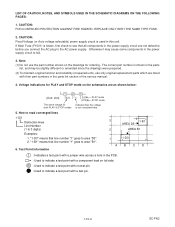
.... (2) To maintain original function and reliability of the service manual. 4. "1-D3" means that the voltage both PLAY & STOP modes is shown in the parts list, and may cause some components in this unit. How to read converged lines 1-D3 Distinction Area Line Number (1 to indicate a test point with a jumper wire across a hole in the parts list section of repaired units, use the part number shown on the...
.... (2) To maintain original function and reliability of the service manual. 4. "1-D3" means that the voltage both PLAY & STOP modes is shown in the parts list, and may cause some components in this unit. How to read converged lines 1-D3 Distinction Area Line Number (1 to indicate a test point with a jumper wire across a hole in the parts list section of repaired units, use the part number shown on the...

Service Manual
Page 33
Fixed voltage ( or Auto voltage selectable ) power supply circuit is used in hot circuit is blown, check to see that all components in the power supply circuit to the AC power supply. Otherwise it may cause some components in the power supply circuit are not defective before you connect the AC plug to fail. CAUTION For continued protection against fire hazard, replace only...
Fixed voltage ( or Auto voltage selectable ) power supply circuit is used in hot circuit is blown, check to see that all components in the power supply circuit to the AC power supply. Otherwise it may cause some components in the power supply circuit are not defective before you connect the AC plug to fail. CAUTION For continued protection against fire hazard, replace only...

Service Manual
Page 48
SYSTEM CONTROL TIMING CHARTS Tray Close ~ Play / Play ~ Tray Open Tray IN (TL221) 3.3V 0V Tray Close Sled Drive (TP303) 1.65V 0V Disc Drive (TP301) 1.65V 0V Focus Drive (TP304) 1.65V 0V Tracking Drive 1.65V (TP302) 0V Disc Rotation Play Disc Tray Stop Open 1-13-1 E5945TI
SYSTEM CONTROL TIMING CHARTS Tray Close ~ Play / Play ~ Tray Open Tray IN (TL221) 3.3V 0V Tray Close Sled Drive (TP303) 1.65V 0V Disc Drive (TP301) 1.65V 0V Focus Drive (TP304) 1.65V 0V Tracking Drive 1.65V (TP302) 0V Disc Rotation Play Disc Tray Stop Open 1-13-1 E5945TI
Service Manual
Page 54
...replacing any of the product through improper servicing. A1X A2 A13 A15 A16 A21# A22 A30 1B1 2B5 2L011 2L021 2L031 2L041 2L081 2L105 S1 S2 S4 X1 X2 X4 X5 X10# FRONT ASSEMBLY E592AZD PANEL,TRAY E5920UD FOOT(REAR) E5710UD CHASSIS(V0) E5946AD CASE, TOP E5 PLASTIC RATING LABEL E592BZD BAR CODE...WASHER+ P-TIGHT SCREW 3X8 BIND + GIFT BOX, CARTON E592BZD SIDE PAD E59A5BD UNIT, BAG E5500UD REMOTE CONTROL UNIT DVD 0842 VCZF05EE DRY BATTERY R6P/2S ACCESSORY BAG E5700UD AV CORD OWNER'S MANUAL E592BZD Description Part No. 9HS1VM220174 9HS0VM204430 9HS0VM415007 9HS0VM204661C 9HS0VM306830A 9HSN79F0HVM...
...replacing any of the product through improper servicing. A1X A2 A13 A15 A16 A21# A22 A30 1B1 2B5 2L011 2L021 2L031 2L041 2L081 2L105 S1 S2 S4 X1 X2 X4 X5 X10# FRONT ASSEMBLY E592AZD PANEL,TRAY E5920UD FOOT(REAR) E5710UD CHASSIS(V0) E5946AD CASE, TOP E5 PLASTIC RATING LABEL E592BZD BAR CODE...WASHER+ P-TIGHT SCREW 3X8 BIND + GIFT BOX, CARTON E592BZD SIDE PAD E59A5BD UNIT, BAG E5500UD REMOTE CONTROL UNIT DVD 0842 VCZF05EE DRY BATTERY R6P/2S ACCESSORY BAG E5700UD AV CORD OWNER'S MANUAL E592BZD Description Part No. 9HS1VM220174 9HS0VM204430 9HS0VM415007 9HS0VM204661C 9HS0VM306830A 9HSN79F0HVM...


