
Service Manual
Page 1
...PARTS LIST ...1-18-1 This document has been published to change without notice. SERVICE MANUAL DV-S2U SERVICE MANUAL S12E4DV-S2U// DVD VIDEO PLAYER POWER OPEN/CLOSE PLAY STOP STILL/PAUSE SKIP REV FWD MODEL DV-S2U In the interests of user-safety (Required by safety regulations in some countries) the ...set should be restored to its original condition and only parts identical to those specified be used for SHARP CORPORATION after sales service only. 1 ...
...PARTS LIST ...1-18-1 This document has been published to change without notice. SERVICE MANUAL DV-S2U SERVICE MANUAL S12E4DV-S2U// DVD VIDEO PLAYER POWER OPEN/CLOSE PLAY STOP STILL/PAUSE SKIP REV FWD MODEL DV-S2U In the interests of user-safety (Required by safety regulations in some countries) the ...set should be restored to its original condition and only parts identical to those specified be used for SHARP CORPORATION after sales service only. 1 ...

Service Manual
Page 2
S/N 3-3. All Items are measured without pre-emphasis unless otherwise specified. 2. Load imp. : 100 K ohm 4. Optical Digital Out 3. Response DVD CD 3-4. Output Level 3-2. THD+N Other Specifications Power consumption Dimensions Weight CONDITIONS 75 ohm load UNIT Vpp dBm NOMINAL 1.0 -18 LIMIT 1kHz 0dB Vrms 2.0 dB 110 fs=48kHz 20~22kH dB fs=44.1kHz 20~20 kHz dB 1 kHz 0dB % ± 2 ± 2 0.005 : 14 W (standby: 2 W) : 17-1/8" (435 mm) x 2-17/32" (75 mm) x 8-5/16" (211 mm) (W / H / D) : 4.62lbs (2.1kg) NOTES: 1. Power supply : AC120 V 60 Hz 3. Room ambient...
S/N 3-3. All Items are measured without pre-emphasis unless otherwise specified. 2. Load imp. : 100 K ohm 4. Optical Digital Out 3. Response DVD CD 3-4. Output Level 3-2. THD+N Other Specifications Power consumption Dimensions Weight CONDITIONS 75 ohm load UNIT Vpp dBm NOMINAL 1.0 -18 LIMIT 1kHz 0dB Vrms 2.0 dB 110 fs=48kHz 20~22kH dB fs=44.1kHz 20~20 kHz dB 1 kHz 0dB % ± 2 ± 2 0.005 : 14 W (standby: 2 W) : 17-1/8" (435 mm) x 2-17/32" (75 mm) x 8-5/16" (211 mm) (W / H / D) : 4.62lbs (2.1kg) NOTES: 1. Power supply : AC120 V 60 Hz 3. Room ambient...

Service Manual
Page 3
Do not look directly at least 30cm away from the pickup lens when the diode is emitted from the pickup or allow it to keep your skin. Drive Mecha Assembly Laser Beam Radiation Laser Pickup Turntable CAUTION LASER RADIATION WHEN OPEN. DO NOT STARE INTO BEAM. Location: Inside Top of controls and adjustments, or doing procedures other than those specified herein, may result in the figure. LASER BEAM SAFETY PRECAUTIONS This DVD player uses a pickup that emits a laser beam. Do not look directly at the laser beam coming from the location shown in hazardous radiation exposure...
Do not look directly at least 30cm away from the pickup lens when the diode is emitted from the pickup or allow it to keep your skin. Drive Mecha Assembly Laser Beam Radiation Laser Pickup Turntable CAUTION LASER RADIATION WHEN OPEN. DO NOT STARE INTO BEAM. Location: Inside Top of controls and adjustments, or doing procedures other than those specified herein, may result in the figure. LASER BEAM SAFETY PRECAUTIONS This DVD player uses a pickup that emits a laser beam. Do not look directly at the laser beam coming from the location shown in hazardous radiation exposure...
Service Manual
Page 6
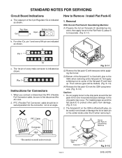
For other parts from the CBA using tweezers. (Fig. When you connect or disconnect the FFC (Flexible Foil Connector) cable, be inserted parallel into the connector, not at an angle. S-1-6) (4) Release the flat pack-IC from damage. (Fig. S-1-2) 2. The 1st pin of the flat pack-IC and heat up. FFC (Flexible Foil Connector) cable should be sure to first disconnect the AC cord. 2. when removing entire flat pack-IC, first apply soldering iron to the CBA; CBA Hot-air Flat Pack-IC Desoldering Machine * Be careful to Remove / Install Flat Pack-IC 1. FFC Cable Connector CBA Fig. ...
For other parts from the CBA using tweezers. (Fig. When you connect or disconnect the FFC (Flexible Foil Connector) cable, be inserted parallel into the connector, not at an angle. S-1-6) (4) Release the flat pack-IC from damage. (Fig. S-1-2) 2. The 1st pin of the flat pack-IC and heat up. FFC (Flexible Foil Connector) cable should be sure to first disconnect the AC cord. 2. when removing entire flat pack-IC, first apply soldering iron to the CBA; CBA Hot-air Flat Pack-IC Desoldering Machine * Be careful to Remove / Install Flat Pack-IC 1. FFC Cable Connector CBA Fig. ...
Service Manual
Page 7
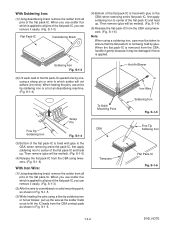
...be melted). (Fig. S-1-3) (2) Affix the wire to lift the IC leads from the CBA contact pads as shown in Fig. S-1-5. S-1-6) Note: When using a sharp pin or wire to which is fixed with glue to all pins of the flat pack-IC, you can remove it easily. (Fig. S-1-5. (3) While heating... or a hot air desoldering machine. (Fig. S-1-3) Flat Pack-IC Desoldering Braid (4) Bottom of the flat pack-IC is applied to the CBA; S-1-4) Sharp Pin Fine Tip Soldering Iron Fig. To Solid Mounting Point CBA Tweezers Hot Air Blower or Iron Wire Soldering Iron Fig. When you use solder...
...be melted). (Fig. S-1-3) (2) Affix the wire to lift the IC leads from the CBA contact pads as shown in Fig. S-1-5. S-1-6) Note: When using a sharp pin or wire to which is fixed with glue to all pins of the flat pack-IC, you can remove it easily. (Fig. S-1-5. (3) While heating... or a hot air desoldering machine. (Fig. S-1-3) Flat Pack-IC Desoldering Braid (4) Bottom of the flat pack-IC is applied to the CBA; S-1-4) Sharp Pin Fine Tip Soldering Iron Fig. To Solid Mounting Point CBA Tweezers Hot Air Blower or Iron Wire Soldering Iron Fig. When you use solder...

Service Manual
Page 8
Then presolder the four corners of the flat pack-IC. Be sure that is indicated by electrostatic charge during unpacking or repair work. 1. Because the static electricity charge on clothing will not escape through the body grounding band, be careful to remove any static electricity that may occur due to be charged on the workbench or other surface, where the semi-conductors are to a potential difference caused by a " " mark. S-1-8 < Correct > Grounding Band CBA Conductive Sheet or Copper Plate 1-4-3 DVD_NOTE 2. Ground for Workbench Be sure to place a conductive sheet or ...
Then presolder the four corners of the flat pack-IC. Be sure that is indicated by electrostatic charge during unpacking or repair work. 1. Because the static electricity charge on clothing will not escape through the body grounding band, be careful to remove any static electricity that may occur due to be charged on the workbench or other surface, where the semi-conductors are to a potential difference caused by a " " mark. S-1-8 < Correct > Grounding Band CBA Conductive Sheet or Copper Plate 1-4-3 DVD_NOTE 2. Ground for Workbench Be sure to place a conductive sheet or ...
Service Manual
Page 9
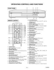
Display,Remote Sensor Window 10. ZOOM Button Enlarges part of a selected section. 23. A-B REPEAT Button Repeats playback of a DVD-reproduced image. 14. ENTER Button Press to a desired point. 22. Disc loading tray 3. Hold down to change setup items. 1-5-1 E56B0IB DIMMER Button Press to fast forward playback. 7. FWD Button Fast forwards playback to accept a setting. 25. AUDIO Button Press to call back the Marker display. 31. SETUP Button Press to enter the setup mode or to fast reverse playback. 8. PLAY Button Starts playback of the next chapter or track. SKIP...
Display,Remote Sensor Window 10. ZOOM Button Enlarges part of a selected section. 23. A-B REPEAT Button Repeats playback of a DVD-reproduced image. 14. ENTER Button Press to a desired point. 22. Disc loading tray 3. Hold down to change setup items. 1-5-1 E56B0IB DIMMER Button Press to fast forward playback. 7. FWD Button Fast forwards playback to accept a setting. 25. AUDIO Button Press to call back the Marker display. 31. SETUP Button Press to enter the setup mode or to fast reverse playback. 8. PLAY Button Starts playback of the next chapter or track. SKIP...
Service Manual
Page 10
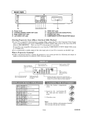
If your TVs or monitors are the BNC type. What is displayed. Stays on 1. No disc inserted Tray open Tray closed Loading the Disc Power off 2. COAXIAL DIGITAL AUDIO OUT Jack 34. Component Video Out Jacks(Y/PB/PR) 38. Unlike conventional interlace scanning, the progressive scan system provides less flickering and images in higher resolution than that of your TV is not compatible with each one oriented correctly. 3. When a chapter or track has switched, the number of a new title, chapter or track is Progressive Scanning? DISPLAYS DURING OPERATION LOADING THE ...
If your TVs or monitors are the BNC type. What is displayed. Stays on 1. No disc inserted Tray open Tray closed Loading the Disc Power off 2. COAXIAL DIGITAL AUDIO OUT Jack 34. Component Video Out Jacks(Y/PB/PR) 38. Unlike conventional interlace scanning, the progressive scan system provides less flickering and images in higher resolution than that of your TV is not compatible with each one oriented correctly. 3. When a chapter or track has switched, the number of a new title, chapter or track is Progressive Scanning? DISPLAYS DURING OPERATION LOADING THE ...
Service Manual
Page 11
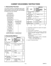
CBA Shield [6] DVD Main CBA Unit 5 Insulator Sheet, - *CN1001, *CN1601, *CN1801 REMOVAL ID/ LOC. PART Fig. P=Spring, L=Locking Tab, S=Screw, CN=Connector, *=Unhook, Unlock, Release, Unplug, or Desolder e.g. 5(S-1) = five Screws (S-1), 2(L-2) = two Locking Tabs (L-2) 5 : Refer to be serviced. of parts to "Reference Notes." 1-6-1 E56B0DC CABINET DISASSEMBLY INSTRUCTIONS 1. RELEASE/UNPLUG/ DESOLDER 1 5(S-1) Note - [2] Front Assembly 2 *2(L-1), Tray Panel, 1-1 *2(L-2), *5(L-3) 1-2 1-3 1-4 1-5 1-6 [3] Front Shield 3 2(S-2) - [4] DVD Mecha 3,4 2(S-3)...
CBA Shield [6] DVD Main CBA Unit 5 Insulator Sheet, - *CN1001, *CN1601, *CN1801 REMOVAL ID/ LOC. PART Fig. P=Spring, L=Locking Tab, S=Screw, CN=Connector, *=Unhook, Unlock, Release, Unplug, or Desolder e.g. 5(S-1) = five Screws (S-1), 2(L-2) = two Locking Tabs (L-2) 5 : Refer to be serviced. of parts to "Reference Notes." 1-6-1 E56B0DC CABINET DISASSEMBLY INSTRUCTIONS 1. RELEASE/UNPLUG/ DESOLDER 1 5(S-1) Note - [2] Front Assembly 2 *2(L-1), Tray Panel, 1-1 *2(L-2), *5(L-3) 1-2 1-3 1-4 1-5 1-6 [3] Front Shield 3 2(S-2) - [4] DVD Mecha 3,4 2(S-3)...

Service Manual
Page 12
Press the OPEN/CLOSE button again to do this, first release two Locking Tabs (A) at the bottom, and then three Locking Tabs (B) at the side.) (Fig. 2) CAUTION 2: Electrostatic breakdown of FPC cable. (Fig. 4) (S-1) [1] Top Cover (S-1) Tray Panel (L-1) (L-1) (A) (L-2) (B) (L-3) [2] Front Assembly (A) Fig. 2 (S-2) (S-3) CN401 [4] DVD Mecha [3] Front Shield CN101 Fig. 3 Fig. 1 (S-1) 1-6-2 E56B0DC Release two Locking Tabs (L-2). Then, release five Locking Tabs (L-3) (to close the Tray. 1-4. Unplug an AC Cord. 1-6. Short the three short lands of FPC cable with ...
Press the OPEN/CLOSE button again to do this, first release two Locking Tabs (A) at the bottom, and then three Locking Tabs (B) at the side.) (Fig. 2) CAUTION 2: Electrostatic breakdown of FPC cable. (Fig. 4) (S-1) [1] Top Cover (S-1) Tray Panel (L-1) (L-1) (A) (L-2) (B) (L-3) [2] Front Assembly (A) Fig. 2 (S-2) (S-3) CN401 [4] DVD Mecha [3] Front Shield CN101 Fig. 3 Fig. 1 (S-1) 1-6-2 E56B0DC Release two Locking Tabs (L-2). Then, release five Locking Tabs (L-3) (to close the Tray. 1-4. Unplug an AC Cord. 1-6. Short the three short lands of FPC cable with ...

Service Manual
Page 13
DVD Mecha A B Short the three short lands by soldering View for A OR Slide Short the three short lands by soldering C Pickup Unit View for B View for C Fig. 4 (S-4) [7] Progure PCB Shield (S-5) [5] DVD Main CBA Shield CN1801 [8] Progressive CBA Unit CN1802 Insulator Sheet (S-6) (L-4) [6] DVD Main CBA Unit CN1001 CN1601 Fig. 5 [9] PRS PCB Holder (S-7) [11] AV CBA (S-9) (S-9) [10] Switch CBA Desolder (S-8) (S-8) (L-5) Fig. 6 1-6-3 E56B0DC
DVD Mecha A B Short the three short lands by soldering View for A OR Slide Short the three short lands by soldering C Pickup Unit View for B View for C Fig. 4 (S-4) [7] Progure PCB Shield (S-5) [5] DVD Main CBA Shield CN1801 [8] Progressive CBA Unit CN1802 Insulator Sheet (S-6) (L-4) [6] DVD Main CBA Unit CN1001 CN1601 Fig. 5 [9] PRS PCB Holder (S-7) [11] AV CBA (S-9) (S-9) [10] Switch CBA Desolder (S-8) (S-8) (L-5) Fig. 6 1-6-3 E56B0DC
Service Manual
Page 14
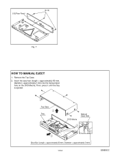
Then, press it until the tray is ejected. Insert the eject-bar (length = approximately 80 mm, diameter = approximately 3 mm) into the manual eject hole on the DVD Mecha. Top Case Tray DVD Mecha Manual Eject Hole Eject-Bar (Length = approximately 80 mm, Diameter = approximately 3 mm) 1-6-4 E56B0DC [12] Rear Panel (S-10) Fig. 7 HOW TO MANUAL EJECT 1. Remove the Top Case. 2.
Then, press it until the tray is ejected. Insert the eject-bar (length = approximately 80 mm, diameter = approximately 3 mm) into the manual eject hole on the DVD Mecha. Top Case Tray DVD Mecha Manual Eject Hole Eject-Bar (Length = approximately 80 mm, Diameter = approximately 3 mm) 1-6-4 E56B0DC [12] Rear Panel (S-10) Fig. 7 HOW TO MANUAL EJECT 1. Remove the Top Case. 2.

Service Manual
Page 15
Displaying VFD "B/E Ver." < Press 1 button on the remote control unit. > All VFD ON/OFF Menu Display (Fig. T-2) Displaying VFD "TEST1" < Press 1 button on the remote control unit. > All VFD ON < Press 2 button on the remote control unit. > All VFD OFF < Press RETURN button on the remote control unit. > Returning to Test Mode Initial Display 1-7-1 TESTMODE Displaying B/E Ver. T-3) Displaying VFD "TEST3" < Press RETURN button on the remote control unit. > Returning to Test Mode Initial Display < Press 3 button on the remote control unit. > Cearing FLASH MEMORY (Fig. Displaying AV ...
Displaying VFD "B/E Ver." < Press 1 button on the remote control unit. > All VFD ON/OFF Menu Display (Fig. T-2) Displaying VFD "TEST1" < Press 1 button on the remote control unit. > All VFD ON < Press 2 button on the remote control unit. > All VFD OFF < Press RETURN button on the remote control unit. > Returning to Test Mode Initial Display 1-7-1 TESTMODE Displaying B/E Ver. T-3) Displaying VFD "TEST3" < Press RETURN button on the remote control unit. > Returning to Test Mode Initial Display < Press 3 button on the remote control unit. > Cearing FLASH MEMORY (Fig. Displaying AV ...

Service Manual
Page 16
TEST1 - TEST4 - DSP . FE . TEST3 - T-1: Test Mode Initial Display FE . FLASH MEMORY CLEAR FLASH MEMORY CLEAR : OK RETURN: RETURN EXIT: POWER Fig. AVD . DSP . 1. BE . T-3: Clearing FLASH MEMORY Display 1-7-2 TESTMODE OFF VFD STATUS AVD . T-2: All VFD ON/OFF Menu Display FE . TEST3 - VFD 2. ON 2. BE . VFD 1. DSP . [ --- ] RETURN: RETURN EXIT: POWER Fig. REPEAT PLAY 3. EEPROM CLEAR 4. TEST1 - BE . MEASUREMENT SERVO RETURN: RETURN EXIT: POWER Fig. TEST2 - AVD .
TEST1 - TEST4 - DSP . FE . TEST3 - T-1: Test Mode Initial Display FE . FLASH MEMORY CLEAR FLASH MEMORY CLEAR : OK RETURN: RETURN EXIT: POWER Fig. AVD . DSP . 1. BE . T-3: Clearing FLASH MEMORY Display 1-7-2 TESTMODE OFF VFD STATUS AVD . T-2: All VFD ON/OFF Menu Display FE . TEST3 - VFD 2. ON 2. BE . VFD 1. DSP . [ --- ] RETURN: RETURN EXIT: POWER Fig. REPEAT PLAY 3. EEPROM CLEAR 4. TEST1 - BE . MEASUREMENT SERVO RETURN: RETURN EXIT: POWER Fig. TEST2 - AVD .

Service Manual
Page 17
Fig. BE F/W VERSION UP MODE PLEASE INSERT A DISC FOR BE F/W VERSION UP. Sending files into the AC outlet. 7. After programming is described as follows: No. f) BE F/W VERSION UP MODE VERSION: ******** COMPLETED SUM:7abc(*3) Fig. In this time, no buttons are available. 6. The DVD player enters the F/W version up mode with the tray open. Turn the power on by pressing the power button and the tray will be shown on the screen while the tray is available.) 4. Erasing previous version data 3 Programming... Fig. c appears on the screen and Fig. f VFD upon ...
Fig. BE F/W VERSION UP MODE PLEASE INSERT A DISC FOR BE F/W VERSION UP. Sending files into the AC outlet. 7. After programming is described as follows: No. f) BE F/W VERSION UP MODE VERSION: ******** COMPLETED SUM:7abc(*3) Fig. In this time, no buttons are available. 6. The DVD player enters the F/W version up mode with the tray open. Turn the power on by pressing the power button and the tray will be shown on the screen while the tray is available.) 4. Erasing previous version data 3 Programming... Fig. c appears on the screen and Fig. f VFD upon ...

Service Manual
Page 18
To put the DVD player into test mode, press [1], [2], [3], [4], and [ON SCREEN] buttons on the VFD. (Fig. a will appear on the screen and the current B/E version will appear on the remote control unit in that order. TEST3-EEPROM CLEAR 4. c will appear on the screen and Fig. LASER POWER RETURN: RETURN POWER EXIT: Fig. e will appear on the screen. e Next Mode Screen 5. Load the disc to measure the error rate and press [OPEN/CLOSE] button or [PLAY] button. To select No. 3 "ERROR RATE," press button [3] on the VFD. Fig. TEST4-MEASUREMENT MODE 5. b VFD in TEST4-MEASUREMENT ...
To put the DVD player into test mode, press [1], [2], [3], [4], and [ON SCREEN] buttons on the VFD. (Fig. a will appear on the screen and the current B/E version will appear on the remote control unit in that order. TEST3-EEPROM CLEAR 4. c will appear on the screen and Fig. LASER POWER RETURN: RETURN POWER EXIT: Fig. e will appear on the screen. e Next Mode Screen 5. Load the disc to measure the error rate and press [OPEN/CLOSE] button or [PLAY] button. To select No. 3 "ERROR RATE," press button [3] on the VFD. Fig. TEST4-MEASUREMENT MODE 5. b VFD in TEST4-MEASUREMENT ...

Service Manual
Page 19
Inner circumference of loaded disc (on DVD: inner circumference of layer 0) 3. The number of layer 1 on loaded disc (on DVD: outer circumference of layer 0) 2. L-0/220000 HEX 3. Outer circumference of loaded disc (on DVD only: when in Measuring Error Rate Mode (example) 9. Fig. h will appear on the screen. h Measuring Error Rate Mode Screen Fig. i) DISC: AUDIO CD STATUS ERROR RATE SELECT NO.[4] 1. 00:02 2. 60:00 NOW MEASURE 1 st PO PI correct uncorrect 2 nd PO (*2) RETURN: RETURN POWER EXIT: (II) when loading CD/VCD Fig. L-0/030000 HEX 2. L-0/030000 HEX...
Inner circumference of loaded disc (on DVD: inner circumference of layer 0) 3. The number of layer 1 on loaded disc (on DVD: outer circumference of layer 0) 2. L-0/220000 HEX 3. Outer circumference of loaded disc (on DVD only: when in Measuring Error Rate Mode (example) 9. Fig. h will appear on the screen. h Measuring Error Rate Mode Screen Fig. i) DISC: AUDIO CD STATUS ERROR RATE SELECT NO.[4] 1. 00:02 2. 60:00 NOW MEASURE 1 st PO PI correct uncorrect 2 nd PO (*2) RETURN: RETURN POWER EXIT: (II) when loading CD/VCD Fig. L-0/030000 HEX 2. L-0/030000 HEX...
Service Manual
Page 20
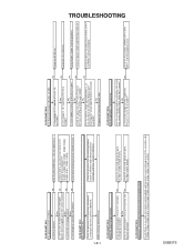
Yes Is the EV 5V line voltage normal? No Yes Is the voltage of IC2001? No Is the voltage of 5V supplied to Pin(26) of the power circuit. Yes No Are the filament voltage applied between these pins and GND? Check R2001, IC2001 and their periphery. Check or replace IC2001 and DVD Main CBA unit. No Yes Is normal state restored when once unplugged No power cord is not functioning. No FLOW CHART NO.2 The fuse blows out. See FLOW CHART No.2 Check if there is any leak or shor-circuit on the primary circuit component? (Q1001, Q1003,T1001, D1001, D1002, D1004, D1005, D1011, ...
Yes Is the EV 5V line voltage normal? No Yes Is the voltage of IC2001? No Is the voltage of 5V supplied to Pin(26) of the power circuit. Yes No Are the filament voltage applied between these pins and GND? Check R2001, IC2001 and their periphery. Check or replace IC2001 and DVD Main CBA unit. No Yes Is normal state restored when once unplugged No power cord is not functioning. No FLOW CHART NO.2 The fuse blows out. See FLOW CHART No.2 Check if there is any leak or shor-circuit on the primary circuit component? (Q1001, Q1003,T1001, D1001, D1002, D1004, D1005, D1011, ...

Service Manual
Page 21
Yes No Is 5V voltage supplied to Pin(3) terminal of Q1011? Original remote control unit is not outputted. Check D1030, D1048, C1035, C1048 and the periphery circuit. Is 3.3V voltage supplied to Pin(25) of Q1002? FLOW CHART NO.13 The disc tray cannot be opened and closed. (It can be done using the remote control unit.) No Is 0V voltage supplied to the emitter of infrared remote control receiver? Yes Is no operation is possible from the remote control unit. Is PON12V voltage supplied to the collector of D1003? FLOW CHART NO.9 PON 5V is not outputted. ...
Yes No Is 5V voltage supplied to Pin(3) terminal of Q1011? Original remote control unit is not outputted. Check D1030, D1048, C1035, C1048 and the periphery circuit. Is 3.3V voltage supplied to Pin(25) of Q1002? FLOW CHART NO.13 The disc tray cannot be opened and closed. (It can be done using the remote control unit.) No Is 0V voltage supplied to the emitter of infrared remote control receiver? Yes Is no operation is possible from the remote control unit. Is PON12V voltage supplied to the collector of D1003? FLOW CHART NO.9 PON 5V is not outputted. ...

Service Manual
Page 22
Yes Replace the DVD Mecha. The malfunction of picture and sound do not operate normally. (1) Replace the DVD Main CBA Unit. Yes Replace the DVD Mecha. No improvement can be found . No improvement can be found. FLOW CHART NO.16 [No Disc] is indicated. (When the focus servo is indicated. (When the laser beam does not light up.) Replace the DVD Main CBA Unit. FLOW CHART NO.18 Both functions of the original DVD Main CBA Unit. No No improvement can be found . No improvement can be found . No Yes Replace the DVD Mecha. FLOW CHART NO.17 [No Disc] is not ...
Yes Replace the DVD Mecha. The malfunction of picture and sound do not operate normally. (1) Replace the DVD Main CBA Unit. Yes Replace the DVD Mecha. No improvement can be found . No improvement can be found. FLOW CHART NO.16 [No Disc] is indicated. (When the focus servo is indicated. (When the laser beam does not light up.) Replace the DVD Main CBA Unit. FLOW CHART NO.18 Both functions of the original DVD Main CBA Unit. No No improvement can be found . No improvement can be found . No Yes Replace the DVD Mecha. FLOW CHART NO.17 [No Disc] is not ...