
Service Manual
Page 1
... OPEN/CLOSE PLAY STOP STILL/PAUSE SKIP REV FWD MODEL DV-S2U In the interests of user-safety (Required by safety regulations in some countries) the set should be restored to its original condition and only parts identical to change without notice. DVD VIDEO PLAYER MODEL DV-S2U CONTENTS Page SPECIFICATIONS ...1-1-1 LASER BEAM SAFETY PRECAUTIONS 1-2-1 IMPORTANT SAFEGUARDS AND PRECAUTIONS 1-3-1 STANDARD NOTES FOR SERVICING 1-4-1 OPERATING CONTROLS AND FUNCTIONS 1-5-1 CABINET DISASSEMBLY INSTRUCTIONS 1-6-1 TEST MODE ...1-7-1 TROUBLESHOOTING ...1-8-1 BLOCK DIAGRAMS ...1-9-1 SCHEMATIC...
... OPEN/CLOSE PLAY STOP STILL/PAUSE SKIP REV FWD MODEL DV-S2U In the interests of user-safety (Required by safety regulations in some countries) the set should be restored to its original condition and only parts identical to change without notice. DVD VIDEO PLAYER MODEL DV-S2U CONTENTS Page SPECIFICATIONS ...1-1-1 LASER BEAM SAFETY PRECAUTIONS 1-2-1 IMPORTANT SAFEGUARDS AND PRECAUTIONS 1-3-1 STANDARD NOTES FOR SERVICING 1-4-1 OPERATING CONTROLS AND FUNCTIONS 1-5-1 CABINET DISASSEMBLY INSTRUCTIONS 1-6-1 TEST MODE ...1-7-1 TROUBLESHOOTING ...1-8-1 BLOCK DIAGRAMS ...1-9-1 SCHEMATIC...

Service Manual
Page 2
S/N 3-3. Load imp. : 100 K ohm 4. Audio (PCM) 3-1. Video Output 2. Room ambient : +25 °C 1-1-1 E56B0SP Freq. Optical Digital Out 3. All Items are measured without pre-emphasis unless otherwise specified. 2. Response DVD CD 3-4. Output Level 3-2. Power supply : AC120 V 60 Hz 3. SPECIFICATIONS ITEM 1. THD+N Other Specifications Power consumption Dimensions Weight CONDITIONS 75 ohm load UNIT Vpp dBm NOMINAL 1.0 -18 LIMIT 1kHz 0dB Vrms 2.0 dB 110 fs=48kHz 20...
S/N 3-3. Load imp. : 100 K ohm 4. Audio (PCM) 3-1. Video Output 2. Room ambient : +25 °C 1-1-1 E56B0SP Freq. Optical Digital Out 3. All Items are measured without pre-emphasis unless otherwise specified. 2. Response DVD CD 3-4. Output Level 3-2. Power supply : AC120 V 60 Hz 3. SPECIFICATIONS ITEM 1. THD+N Other Specifications Power consumption Dimensions Weight CONDITIONS 75 ohm load UNIT Vpp dBm NOMINAL 1.0 -18 LIMIT 1kHz 0dB Vrms 2.0 dB 110 fs=48kHz 20...

Service Manual
Page 3
... Turntable CAUTION LASER RADIATION WHEN OPEN. DO NOT STARE INTO BEAM. Do not look directly at least 30cm away from the pickup lens when the diode is emitted from the pickup or allow it to keep your skin. The laser beam is turned on. LASER BEAM SAFETY PRECAUTIONS This DVD player uses a pickup that emits a laser...
... Turntable CAUTION LASER RADIATION WHEN OPEN. DO NOT STARE INTO BEAM. Do not look directly at least 30cm away from the pickup lens when the diode is emitted from the pickup or allow it to keep your skin. The laser beam is turned on. LASER BEAM SAFETY PRECAUTIONS This DVD player uses a pickup that emits a laser...
Service Manual
Page 6
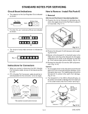
... is affixed with glue to the chip parts may occur. The 1st pin of the 3 pin Regulator ICs is indicated as shown. FFC Cable Connector CBA Fig. The output pin of every male connector is indicated as shown. Top View Input Out In Bottom View How to Remove / Install Flat Pack-IC 1. STANDARD NOTES FOR SERVICING Circuit Board Indications a.
... is affixed with glue to the chip parts may occur. The 1st pin of the 3 pin Regulator ICs is indicated as shown. FFC Cable Connector CBA Fig. The output pin of every male connector is indicated as shown. Top View Input Out In Bottom View How to Remove / Install Flat Pack-IC 1. STANDARD NOTES FOR SERVICING Circuit Board Indications a.
Service Manual
Page 9
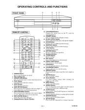
... menus. 27. Disc loading tray 3. Hold down to fast forward playback. 7. CLEAR Button Resets a setting. 19. REV Button Fast reverse playback to select a desired audio language or sound mode. 29. Hold down to fast reverse playback. 8. DIMMER Button Press to the previous operation. 17. ENTER Button Press to call back the Marker display. 31. MODE Button Activates program playback or random playback mode. 30. MARKER Button Press to accept a setting. 25. Numeric Buttons 18. OPERATING CONTROLS AND FUNCTIONS FRONT PANEL 2 3 45 POWER OPEN/CLOSE PLAY STOP STILL/PAUSE...
... menus. 27. Disc loading tray 3. Hold down to fast forward playback. 7. CLEAR Button Resets a setting. 19. REV Button Fast reverse playback to select a desired audio language or sound mode. 29. Hold down to fast reverse playback. 8. DIMMER Button Press to the previous operation. 17. ENTER Button Press to call back the Marker display. 31. MODE Button Activates program playback or random playback mode. 30. MARKER Button Press to accept a setting. 25. Numeric Buttons 18. OPERATING CONTROLS AND FUNCTIONS FRONT PANEL 2 3 45 POWER OPEN/CLOSE PLAY STOP STILL/PAUSE...
Service Manual
Page 10
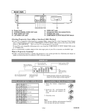
... the DVD player and set your TV is being played back. S-VIDEO OUT Jack 39. When a chapter or track has switched, the number of traditional (480i) television signals. No disc inserted Tray open Tray closed Loading the Disc Power off 2. Do not mix old and new batteries. 1-5-2 E56B0IB Right AUDIO OUT Jack 35. Open the battery compartment cover. If your TV to INTERLACE . REAR VIEW AUDIO OUT VIDEO OUT COMPONENT Y PR DIGITAL R L VIDEO PB S-VIDEO COMPONENT OUTPUT SELECTOR INTERLACE PROGRESSIVE 32...
... the DVD player and set your TV is being played back. S-VIDEO OUT Jack 39. When a chapter or track has switched, the number of traditional (480i) television signals. No disc inserted Tray open Tray closed Loading the Disc Power off 2. Do not mix old and new batteries. 1-5-2 E56B0IB Right AUDIO OUT Jack 35. Open the battery compartment cover. If your TV to INTERLACE . REAR VIEW AUDIO OUT VIDEO OUT COMPONENT Y PR DIGITAL R L VIDEO PB S-VIDEO COMPONENT OUTPUT SELECTOR INTERLACE PROGRESSIVE 32...
Service Manual
Page 11
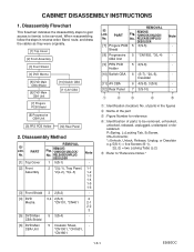
... the cables as they were originally. [1] Top Cover [2] Front Assembly [3] Front Shield [4] DVD Mecha [5] DVD Main CBA Shield [6] DVD Main CBA Unit [10] Switch CBA [11] AV CBA [7] Progure PCB Shield [8] Progressive CBA Unit [9] PRS PCB Holder [12] Rear Panel 2. Disassembly Method ID/ LOC. PART No. [1] Top Cover REMOVAL Fig. REMOVE/ *UNHOOK/UNLOCK/ No. PART Fig. of parts to be serviced. CABINET DISASSEMBLY INSTRUCTIONS 1. CBA Shield [6] DVD...
... the cables as they were originally. [1] Top Cover [2] Front Assembly [3] Front Shield [4] DVD Mecha [5] DVD Main CBA Shield [6] DVD Main CBA Unit [10] Switch CBA [11] AV CBA [7] Progure PCB Shield [8] Progressive CBA Unit [9] PRS PCB Holder [12] Rear Panel 2. Disassembly Method ID/ LOC. PART No. [1] Top Cover REMOVAL Fig. REMOVE/ *UNHOOK/UNLOCK/ No. PART Fig. of parts to be serviced. CABINET DISASSEMBLY INSTRUCTIONS 1. CBA Shield [6] DVD...

Service Manual
Page 12
... cable. (Fig. 4) (S-1) [1] Top Cover (S-1) Tray Panel (L-1) (L-1) (A) (L-2) (B) (L-3) [2] Front Assembly (A) Fig. 2 (S-2) (S-3) CN401 [4] DVD Mecha [3] Front Shield CN101 Fig. 3 Fig. 1 (S-1) 1-6-2 E56B0DC Remove the Tray Panel by electrostatic charge accumulated on cloth, human body etc., during unpacking or repair work. Connect the wall plug to an AC outlet and press the OPEN/CLOSE button to close the Tray. 1-4. Reference Notes CAUTION 1: Locking Tabs (L-1), (L-2) and (L-3) are fragile. Remove two Screws (S-3) and lift the DVD...
... cable. (Fig. 4) (S-1) [1] Top Cover (S-1) Tray Panel (L-1) (L-1) (A) (L-2) (B) (L-3) [2] Front Assembly (A) Fig. 2 (S-2) (S-3) CN401 [4] DVD Mecha [3] Front Shield CN101 Fig. 3 Fig. 1 (S-1) 1-6-2 E56B0DC Remove the Tray Panel by electrostatic charge accumulated on cloth, human body etc., during unpacking or repair work. Connect the wall plug to an AC outlet and press the OPEN/CLOSE button to close the Tray. 1-4. Reference Notes CAUTION 1: Locking Tabs (L-1), (L-2) and (L-3) are fragile. Remove two Screws (S-3) and lift the DVD...

Service Manual
Page 17
... files into version up mode with the tray open . 3. In this time, no buttons are available. 6. e Completed Program Mode Screen Fig. To put the DVD player into the memory 2 Erasing... Fig. e appears on the VFD. The DVD player enters the F/W version up . (For closing the tray, only the "OPEN/CLOSE" button is described as follows: No. d appears on the screen and the checksum in that order. Turn the power on the remote control...
... files into version up mode with the tray open . 3. In this time, no buttons are available. 6. e Completed Program Mode Screen Fig. To put the DVD player into the memory 2 Erasing... Fig. e appears on the VFD. The DVD player enters the F/W version up . (For closing the tray, only the "OPEN/CLOSE" button is described as follows: No. d appears on the screen and the checksum in that order. Turn the power on the remote control...

Service Manual
Page 18
... tray and close the tray automatically and fig. b VFD in that order. To select No. 1 "NEXT," press button [1] on the remote control unit. Fig. Load the disc to measure the error rate and press [OPEN/CLOSE] button or [PLAY] button. Turn the power on the VFD. (Fig. d will not change . To select No. 3 "ERROR RATE," press button [3] on the remote control unit. To select No. 4 "TEST4-MEASUREMENT MODE," press button [4] on the remote control unit. To put the DVD player...
... tray and close the tray automatically and fig. b VFD in that order. To select No. 1 "NEXT," press button [1] on the remote control unit. Fig. Load the disc to measure the error rate and press [OPEN/CLOSE] button or [PLAY] button. Turn the power on the VFD. (Fig. d will not change . To select No. 3 "ERROR RATE," press button [3] on the remote control unit. To select No. 4 "TEST4-MEASUREMENT MODE," press button [4] on the remote control unit. To put the DVD player...

Service Manual
Page 19
... measured using number buttons on DVD only: when in Measuring Error Rate Mode (example) 9. L-1/E00000 HEX RETURN: RETURN POWER EXIT: (I ) when loading DVD E56***D FE *.*** BE *.*** AVD *.* TEST4-MEASUREMENT MODE DISC: AUDIO CD TIME: **:** STATUS PLAY MODE-ERROR RATE 1. 00:02 2. 60:00 RETURN: RETURN EXIT: (II) when loading CD/VCD Fig. L-1/E00000 HEX NOW MEASURE:******H - ******H 1 st PO PI 2 nd PO correct uncorrect (*2) RETURN: RETURN POWER EXIT: (I ) when loading DVD DISC:DVD...
... measured using number buttons on DVD only: when in Measuring Error Rate Mode (example) 9. L-1/E00000 HEX RETURN: RETURN POWER EXIT: (I ) when loading DVD E56***D FE *.*** BE *.*** AVD *.* TEST4-MEASUREMENT MODE DISC: AUDIO CD TIME: **:** STATUS PLAY MODE-ERROR RATE 1. 00:02 2. 60:00 RETURN: RETURN EXIT: (II) when loading CD/VCD Fig. L-1/E00000 HEX NOW MEASURE:******H - ******H 1 st PO PI 2 nd PO correct uncorrect (*2) RETURN: RETURN POWER EXIT: (I ) when loading DVD DISC:DVD...
Service Manual
Page 20
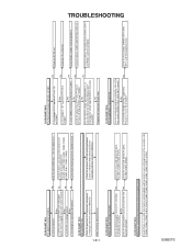
... No operate normally? Check the circuit and replace the parts. (IC1001, IC1006, D1048, D1015) Check the circuit and replace the parts. (IC1001, D1012, D1024) FLOW CHART NO.4 When buzz sound can be turned on the rectifying diode and the circuit in each rectifying circuit of IC2001? Also negative voltage applied between (1, 2) and (34, 35) of the power circuit...
... No operate normally? Check the circuit and replace the parts. (IC1001, IC1006, D1048, D1015) Check the circuit and replace the parts. (IC1001, D1012, D1024) FLOW CHART NO.4 When buzz sound can be turned on the rectifying diode and the circuit in each rectifying circuit of IC2001? Also negative voltage applied between (1, 2) and (34, 35) of the power circuit...

Service Manual
Page 21
... on the loaded circuit. No Yes Replace Q1004. FLOW CHART NO.13 The disc tray cannot be opened and closed. (It can be done using the remote control unit.) No Is 0V voltage supplied to Pin(25) of CN1001 when the OPEN/CLOSE button is outputted normally.) Is 5V voltage supplied to Pin(26) of CN1001 from Pin(1) terminal of infrared remote control receiver? Check D1046...
... on the loaded circuit. No Yes Replace Q1004. FLOW CHART NO.13 The disc tray cannot be opened and closed. (It can be done using the remote control unit.) No Is 0V voltage supplied to Pin(25) of CN1001 when the OPEN/CLOSE button is outputted normally.) Is 5V voltage supplied to Pin(26) of CN1001 from Pin(1) terminal of infrared remote control receiver? Check D1046...
Service Manual
Page 23
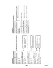
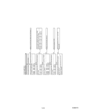
... 21PIN U IC1402 18PIN V Yes Are the video signals outputted to the S-OUT terminal (JK1401)? No Are the chroma signals outputted to the specific output terminal? CN1601 7PIN → IC1402 4PIN CVBS...cable (W1801) connecting CN1801 on the disc tray and playback. FLOW CHART NO.20 Component video signals are not outputted normally in interlace No mode? Set the disc on the No AV CBA and Progressive CBA Unit normally? Yes Yes Are the video signals outputted to the VIDEO OUT terminal (JK1403)? Yes Replace Progressive CBA Unit. E56B0TS 1-8-4 FLOW CHART NO.19 Picture...
... 21PIN U IC1402 18PIN V Yes Are the video signals outputted to the S-OUT terminal (JK1401)? No Are the chroma signals outputted to the specific output terminal? CN1601 7PIN → IC1402 4PIN CVBS...cable (W1801) connecting CN1801 on the disc tray and playback. FLOW CHART NO.20 Component video signals are not outputted normally in interlace No mode? Set the disc on the No AV CBA and Progressive CBA Unit normally? Yes Yes Are the video signals outputted to the VIDEO OUT terminal (JK1403)? Yes Replace Progressive CBA Unit. E56B0TS 1-8-4 FLOW CHART NO.19 Picture...
Service Manual
Page 24
... disc tray and playback. CN1601 13PIN AUDIO-L CN1601 15PIN AUDIO-R Yes Are the analog audio signals inputted to the L/R OUT terminal (JK1201)? IC1201 1PIN AUDIO-L No IC1201 7PIN AUDIO-R Yes Are the audio signals outputted to each pin of CN1601 on the AV CBA ? Set the disc on the AV CBA. E56B0TS 1-8-5 FLOW CHART NO.21 Audio is not outputted. No Are the analog audio signals outputted to the specific No output...
... disc tray and playback. CN1601 13PIN AUDIO-L CN1601 15PIN AUDIO-R Yes Are the analog audio signals inputted to the L/R OUT terminal (JK1201)? IC1201 1PIN AUDIO-L No IC1201 7PIN AUDIO-R Yes Are the audio signals outputted to each pin of CN1601 on the AV CBA ? Set the disc on the AV CBA. E56B0TS 1-8-5 FLOW CHART NO.21 Audio is not outputted. No Are the analog audio signals outputted to the specific No output...
Service Manual
Page 32
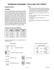
... not use of these drawings for higher voltage, wattage, etc. Replacement parts that do not have special characteristics. CBA Symbols (Top View) (Bottom View) + Electrolytic Capacitor (Bottom View) E C B Transistor or Digital Transistor (Top View) (Top View) NPN Transistor PNP Transistor E C B (Top View) NPN Digital Transistor E C B E C B (Top View) PNP Digital Transistor E C B 1-10-1 Schematic Diagram Symbols Digital Transistor SC-FN1 The correct part number is shown in the schematic diagram and the parts list...
... not use of these drawings for higher voltage, wattage, etc. Replacement parts that do not have special characteristics. CBA Symbols (Top View) (Bottom View) + Electrolytic Capacitor (Bottom View) E C B Transistor or Digital Transistor (Top View) (Top View) NPN Transistor PNP Transistor E C B (Top View) NPN Digital Transistor E C B E C B (Top View) PNP Digital Transistor E C B 1-10-1 Schematic Diagram Symbols Digital Transistor SC-FN1 The correct part number is shown in the schematic diagram and the parts list...
Service Manual
Page 33
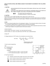
... fast operating fuse. 2. Fixed Voltage (or Auto voltage selectable) power supply circuit is not consistent here. 7. How to read converged lines 1-D3 Distinction Area 3 Line Number (1 to area "D3". 2. LIST OF CAUTION, NOTES, AND SYMBOLS USED IN THE SCHEMATIC DIAGRAMS ON THE FOLLOWING PAGES: 1. RISK OF FIRE-REPLACE FUSE AS MARKED. If Main Fuse (F1001) is blown, first check to see that all components...
... fast operating fuse. 2. Fixed Voltage (or Auto voltage selectable) power supply circuit is not consistent here. 7. How to read converged lines 1-D3 Distinction Area 3 Line Number (1 to area "D3". 2. LIST OF CAUTION, NOTES, AND SYMBOLS USED IN THE SCHEMATIC DIAGRAMS ON THE FOLLOWING PAGES: 1. RISK OF FIRE-REPLACE FUSE AS MARKED. If Main Fuse (F1001) is blown, first check to see that all components...

Service Manual
Page 37
...fast operating fuse." If Main Fuse (F1001) is used in the power supply circuit to the AC power supply. Position ICS IC604 W-2 IC801 Y-1 CONNECTOR CN701 AA-2 1-10-13 E56B0SCD4 AV 1/3 Ref No. Fixed voltage power supply circuit is blown, check to see that all components in hot circuit is measured using... voltage for parts in the power supply circuit are not defective before you connect the AC plug to fail. F A V CAUTION FOR CONTINUED PROTECTION AGAINST FIRE HAZARD, REPLACE ONLY WITH THE SAME TYPE FUSE. DVD Main 4/4 Schematic Diagram AV 1/3 Schematic Diagram 1-10-12...
...fast operating fuse." If Main Fuse (F1001) is used in the power supply circuit to the AC power supply. Position ICS IC604 W-2 IC801 Y-1 CONNECTOR CN701 AA-2 1-10-13 E56B0SCD4 AV 1/3 Ref No. Fixed voltage power supply circuit is blown, check to see that all components in hot circuit is measured using... voltage for parts in the power supply circuit are not defective before you connect the AC plug to fail. F A V CAUTION FOR CONTINUED PROTECTION AGAINST FIRE HAZARD, REPLACE ONLY WITH THE SAME TYPE FUSE. DVD Main 4/4 Schematic Diagram AV 1/3 Schematic Diagram 1-10-12...

Service Manual
Page 43
... DE MEMO TYPE. AV CBA Bottom View BECAUSE A HOT CHASSIS GROUND IS PRESENT IN THE POWER SUPPLY CIRCUIT, AN ISOLATION TRANSFORMER MUST BE USED. ALSO, IN ORDER TO HAVE THE ABILITY TO INCREASE THE INPUT SLOWLY, WHEN TROUBLESHOOTING THIS TYPE POWER SUPPLY CIRCUIT, A VARIABLE ISOLATION TRANSFORMER IS REQUIRED. RISK OF FIRE-REPLACE FUSE AS MARKED. "This symbol means fast operating fuse...
... DE MEMO TYPE. AV CBA Bottom View BECAUSE A HOT CHASSIS GROUND IS PRESENT IN THE POWER SUPPLY CIRCUIT, AN ISOLATION TRANSFORMER MUST BE USED. ALSO, IN ORDER TO HAVE THE ABILITY TO INCREASE THE INPUT SLOWLY, WHEN TROUBLESHOOTING THIS TYPE POWER SUPPLY CIRCUIT, A VARIABLE ISOLATION TRANSFORMER IS REQUIRED. RISK OF FIRE-REPLACE FUSE AS MARKED. "This symbol means fast operating fuse...
Service Manual
Page 53
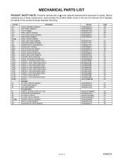
... safety of these components, read carefully the product safety notice in this service manual. Ref. MECHANICAL PARTS LIST PRODUCT SAFETY NOTE: Products marked with a # have special characteristics important to safety. Before replacing any of the product through improper servicing. A1X A2 A13... 18P FFC PACKING GIFT BOX CARTON E56B0UD STYROFOAM E56A0UD UNIT, BAG E56A0UD ACCESSORIES REMOTE CONTROL UNIT R-25 1738 ACCESSORY BAG E56A0UD AV CORD LP-970124 AV CORD TSCKA-Y/RW100 OWNER'S MANUAL E56B0UD NETFLIX CARD E56A0UD REGISTRATION CARD E56A0UD Part No. 9HS0VM203637 9HS0VM203485 9HS0VM411398...
... safety of these components, read carefully the product safety notice in this service manual. Ref. MECHANICAL PARTS LIST PRODUCT SAFETY NOTE: Products marked with a # have special characteristics important to safety. Before replacing any of the product through improper servicing. A1X A2 A13... 18P FFC PACKING GIFT BOX CARTON E56B0UD STYROFOAM E56A0UD UNIT, BAG E56A0UD ACCESSORIES REMOTE CONTROL UNIT R-25 1738 ACCESSORY BAG E56A0UD AV CORD LP-970124 AV CORD TSCKA-Y/RW100 OWNER'S MANUAL E56B0UD NETFLIX CARD E56A0UD REGISTRATION CARD E56A0UD Part No. 9HS0VM203637 9HS0VM203485 9HS0VM411398...


