

Service Manual
Page 11
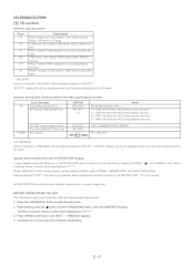
... Button 9. Tape 1 Cassette Compartment 11. Tape 2 Cassette Compartment 23. Memory Indicator 5. Cooling Fan 2. CD-ES900/CD-ES99 [2] Names of parts CD-ES900/CD-ES99 Front panel 1. CD Button 25. Disc Number Indicators 2. Daily Timer Indicator 11. AC Power Cord 3. Power On/Stand-by ...Play Indicator 15. Disc Number Select Buttons 6 14. Tape (1 2) Button 26. CD Pause Indicator 4. Tuning Down Button 8. FM Stereo Mode Indicator 10. FM Stereo Receiving Indicator 12. CD Play or Repeat, Tape Play Button 17. Headphone Jack 12. Timer Indicator 3. ...
... Button 9. Tape 1 Cassette Compartment 11. Tape 2 Cassette Compartment 23. Memory Indicator 5. Cooling Fan 2. CD-ES900/CD-ES99 [2] Names of parts CD-ES900/CD-ES99 Front panel 1. CD Button 25. Disc Number Indicators 2. Daily Timer Indicator 11. AC Power Cord 3. Power On/Stand-by ...Play Indicator 15. Disc Number Select Buttons 6 14. Tape (1 2) Button 26. CD Pause Indicator 4. Tuning Down Button 8. FM Stereo Mode Indicator 10. FM Stereo Receiving Indicator 12. CD Play or Repeat, Tape Play Button 17. Headphone Jack 12. Timer Indicator 3. ...
Service Manual
Page 14
...PLL UNLOCK (*) CHECKING: If Error is detected, 'CHECKING' will be displayed instead of 'ER-CD**'. 'ER-CD**' display will be displayed instead of Stereo System Error Message Display Contents Error Contents CD Pickup Mechanism Error. Press 'VIDEO/AUX' button during initialize process. The Micro Computer version number ...5th times. While pressing down the button and the X-BASS/DEMO button, press the ON/STAD-BY button. DISPLAY 'ER-CD01' 'ER-CD**' (*) Notes PU-IN SW Detection NG. 10: CAM SW Detection NG during normal operation. 11: CAM SW Detection NG during initialize process....
...PLL UNLOCK (*) CHECKING: If Error is detected, 'CHECKING' will be displayed instead of 'ER-CD**'. 'ER-CD**' display will be displayed instead of Stereo System Error Message Display Contents Error Contents CD Pickup Mechanism Error. Press 'VIDEO/AUX' button during initialize process. The Micro Computer version number ...5th times. While pressing down the button and the X-BASS/DEMO button, press the ON/STAD-BY button. DISPLAY 'ER-CD01' 'ER-CD**' (*) Notes PU-IN SW Detection NG. 10: CAM SW Detection NG during normal operation. 11: CAM SW Detection NG during initialize process....

Service Manual
Page 54
...AM GND OUT FM+B AM IF AM MIX L 14 R 15 24 23 21 7 18 16 12 STEREO AM OSC OUT AM OSC IN AM RF IN 1 OSC BUFF 2 CNP301 Q302 AM TRACKING T303 T306 AM... DI CLK DO MOTOR DRIVER Q706 +B7 Q711 Q712 +B7 Q707 Q708 Q714~ Q717 SOLENOID DRIVER CNP5 FROM CD SECTION TAPE MECHANISM ASS'Y IC302 LC72131 PLL(TUNER) FM+B 20 1 22 15 16 11 OSC +B4 Q360...L9 DI 1 R 16 CE 2 TAPE TUNER L 10 R 15 L 11 R 14 IC601 CLK 24 Ð20dB LC75341 ATT Q601 AUDIO PROCESSOR 21 R Q602 CD L 12 4L R 13 7 18 3 Q603 Q604 TAPE 1 L-CH P.B. R-CH AC BIAS SWITCHING Q101~ Q104 L(T1) 1 R(T1) 24 L(T2) ...
...AM GND OUT FM+B AM IF AM MIX L 14 R 15 24 23 21 7 18 16 12 STEREO AM OSC OUT AM OSC IN AM RF IN 1 OSC BUFF 2 CNP301 Q302 AM TRACKING T303 T306 AM... DI CLK DO MOTOR DRIVER Q706 +B7 Q711 Q712 +B7 Q707 Q708 Q714~ Q717 SOLENOID DRIVER CNP5 FROM CD SECTION TAPE MECHANISM ASS'Y IC302 LC72131 PLL(TUNER) FM+B 20 1 22 15 16 11 OSC +B4 Q360...L9 DI 1 R 16 CE 2 TAPE TUNER L 10 R 15 L 11 R 14 IC601 CLK 24 Ð20dB LC75341 ATT Q601 AUDIO PROCESSOR 21 R Q602 CD L 12 4L R 13 7 18 3 Q603 Q604 TAPE 1 L-CH P.B. R-CH AC BIAS SWITCHING Q101~ Q104 L(T1) 1 R(T1) 24 L(T2) ...
Service Manual
Page 56
... symbol P means pico-farad and the unit of the capacitor without such a symbol is microfarad. In the tuner section, indicates AM indicates FM stereo 2. In the CD section, the CD is ohm-type resistor. Be sure to change for improvement without any symbol is stopped. • Parts marked with " " ( ) are subject to replace... SW1 TRAY SW2 DISC POWER ON/STAND-BY CLOCK/TIMER TUNING UP TUNING DOWN FAST REWIND/PRESET DOWN EQUALIZER FAST FORWARD/PRESET UP TUNER (BAND) CD POSITION ON-OFF ON-OFF ON-OFF ON-OFF ON-OFF ON-OFF ON-OFF ON-OFF ON-OFF ON-OFF ON-OFF ON-OFF...
... symbol P means pico-farad and the unit of the capacitor without such a symbol is microfarad. In the tuner section, indicates AM indicates FM stereo 2. In the CD section, the CD is ohm-type resistor. Be sure to change for improvement without any symbol is stopped. • Parts marked with " " ( ) are subject to replace... SW1 TRAY SW2 DISC POWER ON/STAND-BY CLOCK/TIMER TUNING UP TUNING DOWN FAST REWIND/PRESET DOWN EQUALIZER FAST FORWARD/PRESET UP TUNER (BAND) CD POSITION ON-OFF ON-OFF ON-OFF ON-OFF ON-OFF ON-OFF ON-OFF ON-OFF ON-OFF ON-OFF ON-OFF ON-OFF...

Service Manual
Page 69
....7 MHz C398 100/10 R388 3.9K C355 22P(CH) C370 1/50 C357 R355 2.2/50 3.3K C356 0.001 R353 270 12 C358 1/50 10 11 9 78 STEREO FM DET VCC MPX VCO MPX IN IF OUT PHASE R-CH OUT L-CH OUT PHASE (FM/AM) MO/ST 17 16 X351 456 kHz C368... 0.015 C373 0.015 C372 1/50 15 14 13 C371 1/50 IC303 LA1832S FM IF DET./FM MPX./AM IF TP302 TP FM SIGNAL AM SIGNAL CD-ES900/CD-ES99 6 - 11 Figure 6-11 SCHEMATIC DIAGRAM (4/10) 12 11 10 9 8 7 6 - 9 11 -
....7 MHz C398 100/10 R388 3.9K C355 22P(CH) C370 1/50 C357 R355 2.2/50 3.3K C356 0.001 R353 270 12 C358 1/50 10 11 9 78 STEREO FM DET VCC MPX VCO MPX IN IF OUT PHASE R-CH OUT L-CH OUT PHASE (FM/AM) MO/ST 17 16 X351 456 kHz C368... 0.015 C373 0.015 C372 1/50 15 14 13 C371 1/50 IC303 LA1832S FM IF DET./FM MPX./AM IF TP302 TP FM SIGNAL AM SIGNAL CD-ES900/CD-ES99 6 - 11 Figure 6-11 SCHEMATIC DIAGRAM (4/10) 12 11 10 9 8 7 6 - 9 11 -


