
Service Manual
Page 1
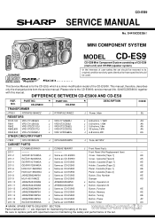
... of user-safety the set . CD-ES9 SERVICE MANUAL No. Please refer to those specified should be restored to its original condition and only parts identical to the CD-ES900, service manual (No. Be sure to replace parts with this manual. This manual, therefore, describes only the changed points from the service manual. DIFFERENCE BETWEEN CD-ES900 AND CD-ES9 REF. S4419CDES9/// MINI COMPONENT SYSTEM MODEL CD-ES9 CD-ES9 Mini Component System consisting of CD-ES9 (main unit) and CP-ES9 (speaker...
... of user-safety the set . CD-ES9 SERVICE MANUAL No. Please refer to those specified should be restored to its original condition and only parts identical to the CD-ES900, service manual (No. Be sure to replace parts with this manual. This manual, therefore, describes only the changed points from the service manual. DIFFERENCE BETWEEN CD-ES900 AND CD-ES9 REF. S4419CDES9/// MINI COMPONENT SYSTEM MODEL CD-ES9 CD-ES9 Mini Component System consisting of CD-ES9 (main unit) and CP-ES9 (speaker...
Service Manual
Page 2
... Used PFLT-A006AWZZ PCoVQ7004AWFW LX-JZ0036AWFD DESCRIPTION Badge, SHARP Spring, Cassette [Tape 1] Spring, Cassette [Tape 2] Volume Knob Ring, A Volume Knob Ring, B J Decoration Plate, Amp Lock, Cassette [Tape 1] Lock, Cassette [Tape 2] Spring, Cassette Lock [Tape 1] Spring, Cassette Lock [Tape 2] J Rear Panel, B [CD-SE9] Sheet, Edge Light J Felt J Cover, Fan J Screw, Special ACCESSORIES TiNSEA002AWZZ TiNSZA003AWZZ TLABZA092AWZZ J TiNSEA055AWZZ J TiNSZA069AWZZ J TLABZA113AWSA J Operation Manual J Quick Guide J Energy Star Label (Set) P.W.B. Be sure to replace parts with...
... Used PFLT-A006AWZZ PCoVQ7004AWFW LX-JZ0036AWFD DESCRIPTION Badge, SHARP Spring, Cassette [Tape 1] Spring, Cassette [Tape 2] Volume Knob Ring, A Volume Knob Ring, B J Decoration Plate, Amp Lock, Cassette [Tape 1] Lock, Cassette [Tape 2] Spring, Cassette Lock [Tape 1] Spring, Cassette Lock [Tape 2] J Rear Panel, B [CD-SE9] Sheet, Edge Light J Felt J Cover, Fan J Screw, Special ACCESSORIES TiNSEA002AWZZ TiNSZA003AWZZ TLABZA092AWZZ J TiNSEA055AWZZ J TiNSZA069AWZZ J TLABZA113AWSA J Operation Manual J Quick Guide J Energy Star Label (Set) P.W.B. Be sure to replace parts with...
Service Manual
Page 4
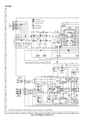
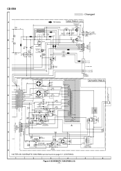
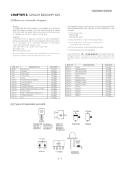
...POWER SECTION C A_GND 6 R-CH 15 CD_D_GND 16 CD_A_GND 17 AGC 26 D FM SIGNAL PLAYBACK SIGNAL RECORD SIGNAL CD SIGNAL VIDEO SIGNAL AUX SIGNAL... C653 220P AUDIO PROCESSOR R605 ...CD-ES9 A BI601 1 R-CH 1 6 - 17 12 - AUX DECK RSEL0 17 R4 16 R3 15 C621 1/50 C623 1/50 11 L2 12 L1 TUNER CD...AMP. C6 1/5 C6 1/5 C6 1/5 C624 1/50 C626 0.0022 R608 C625 0.0022 R609 2.2K C640 22/50 R620 22K C639 1/50 R621 22K R149 150 C141 100/16 SWITCHING...SWITCHING R111 15K H • NOTES ON SCHEMATIC DIAGRAM can be found on page 5-1 (CD-ES900). 1 2 3 4 5 6 Figure 4 SCHEMATIC DIAGRAM (1/3) - 4 -
...POWER SECTION C A_GND 6 R-CH 15 CD_D_GND 16 CD_A_GND 17 AGC 26 D FM SIGNAL PLAYBACK SIGNAL RECORD SIGNAL CD SIGNAL VIDEO SIGNAL AUX SIGNAL... C653 220P AUDIO PROCESSOR R605 ...CD-ES9 A BI601 1 R-CH 1 6 - 17 12 - AUX DECK RSEL0 17 R4 16 R3 15 C621 1/50 C623 1/50 11 L2 12 L1 TUNER CD...AMP. C6 1/5 C6 1/5 C6 1/5 C624 1/50 C626 0.0022 R608 C625 0.0022 R609 2.2K C640 22/50 R620 22K C639 1/50 R621 22K R149 150 C141 100/16 SWITCHING...SWITCHING R111 15K H • NOTES ON SCHEMATIC DIAGRAM can be found on page 5-1 (CD-ES900). 1 2 3 4 5 6 Figure 4 SCHEMATIC DIAGRAM (1/3) - 4 -
Service Manual
Page 5
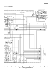
...47K 11.6V R141 2 0V Q109 4.7K 1 KTA1504 GR SWITCHING 3 0V R142 82(1/2W) C131 47/25 BIAS OSC Y...VIDEO IN L-CH AUX/VIDEO R-CH JK690 GAME INPUT CHASSIS 6 - 11 10, 11 - D~H TO POWER SECTION CE 16 DO 15 CLK 14 DI 13 +B_PROTECT 12 D_GND 11 S_MUTE 10 T_T1/T2 9 REC/PLAY 8 T_BIAS 7 A+10V 6 M_+13V 5 SW_5V 4 SP_DET 3 SP_RLY 2 -20dB 1 CNP701B 7 8 9 10 11 12 Figure 5 SCHEMATIC DIAGRAM...TUNER SECTION CE 1 +B A+10V 5 DGND 7 DI 2 CLK 3 TUN_R 8 AGND 6 TUN_L 9 DO 4 C626 0.0022 R608 2.2K CNP701A 6-14 1 - : Changed CD-ES9 D690 DS1SS133 D691 DS1SS133 MAIN PWB-A1 (1/3) JK691 VIDEO...
...47K 11.6V R141 2 0V Q109 4.7K 1 KTA1504 GR SWITCHING 3 0V R142 82(1/2W) C131 47/25 BIAS OSC Y...VIDEO IN L-CH AUX/VIDEO R-CH JK690 GAME INPUT CHASSIS 6 - 11 10, 11 - D~H TO POWER SECTION CE 16 DO 15 CLK 14 DI 13 +B_PROTECT 12 D_GND 11 S_MUTE 10 T_T1/T2 9 REC/PLAY 8 T_BIAS 7 A+10V 6 M_+13V 5 SW_5V 4 SP_DET 3 SP_RLY 2 -20dB 1 CNP701B 7 8 9 10 11 12 Figure 5 SCHEMATIC DIAGRAM...TUNER SECTION CE 1 +B A+10V 5 DGND 7 DI 2 CLK 3 TUN_R 8 AGND 6 TUN_L 9 DO 4 C626 0.0022 R608 2.2K CNP701A 6-14 1 - : Changed CD-ES9 D690 DS1SS133 D691 DS1SS133 MAIN PWB-A1 (1/3) JK691 VIDEO...
Service Manual
Page 6
...R843 47K RELAY DRIVER Q841 KTC3199 GR C841 1000/6.3 D842 D845 1N4004S 1N4004S D844 1N4004S D843 1N4004S C842 470/35 C843 0.047(ML) PT841 SUB POWER TRANSFORMER • NOTES ON SCHEMATIC DIAGRAM can be found on page 5-1 (CD-ES900). 1 2 3 4 5 6 Figure 6 SCHEMATIC DIAGRAM (3/3) - 6 - CD-ES9 : Changed AC POWER SUPPLY CORD AC 120V, ...VF1 5 +B Q801 ZD801 KTA1274 Y DZ6.2BSA VOLTAGE REGULATOR 6 G R841 220K 6 OHMS MIN SP_L1-CH_GND SP_R1-CH_GND SO901 SPEAKER TERMINAL POWER PWB-B1 F805 6A/125V T.F. A TO GAME INPUT PWB 56K R935 56K L901 L 3 µH C929 0.1 (ML) R939 10 (1/...
...R843 47K RELAY DRIVER Q841 KTC3199 GR C841 1000/6.3 D842 D845 1N4004S 1N4004S D844 1N4004S D843 1N4004S C842 470/35 C843 0.047(ML) PT841 SUB POWER TRANSFORMER • NOTES ON SCHEMATIC DIAGRAM can be found on page 5-1 (CD-ES900). 1 2 3 4 5 6 Figure 6 SCHEMATIC DIAGRAM (3/3) - 6 - CD-ES9 : Changed AC POWER SUPPLY CORD AC 120V, ...VF1 5 +B Q801 ZD801 KTA1274 Y DZ6.2BSA VOLTAGE REGULATOR 6 G R841 220K 6 OHMS MIN SP_L1-CH_GND SP_R1-CH_GND SO901 SPEAKER TERMINAL POWER PWB-B1 F805 6A/125V T.F. A TO GAME INPUT PWB 56K R935 56K L901 L 3 µH C929 0.1 (ML) R939 10 (1/...
Service Manual
Page 9
... control shafts, escutcheon, etc.) and measure the AC voltage drop across the resistor. CD-ES900/CD-ES99 IMPORTANT SERVICE NOTES BEFORE RETURNING THE AUDIO PRODUCT BEFORE RETURNING THE AUDIO PRODUCT (Fire & Shock Hazard) Before returning the audio product to the user, perform the following manner. * Plug the AC line cord directly into a 120 volt AC outlet. * Using two clip leads, connect a 1.5 kohm, 10 watt...
... control shafts, escutcheon, etc.) and measure the AC voltage drop across the resistor. CD-ES900/CD-ES99 IMPORTANT SERVICE NOTES BEFORE RETURNING THE AUDIO PRODUCT BEFORE RETURNING THE AUDIO PRODUCT (Fire & Shock Hazard) Before returning the audio product to the user, perform the following manner. * Plug the AC line cord directly into a 120 volt AC outlet. * Using two clip leads, connect a 1.5 kohm, 10 watt...
Service Manual
Page 10
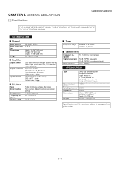
....1 lbs. (10.0 kg) 200 watts minimum RMS per channel into 6 ohms from 100 Hz to 20 kHz, 10% total harmonic distortion Speakers: 6 ohms Headphones: 16 - 50 ohms (recommended: 32 ohms) Video output: 1Vp-p Game/Auxiliary (audio signal): 500 mV/47 k ohms Game/Video: 1Vp-p 5-disc multi-play compact disc player Non-contact, 3-beam semiconductor laser pickup 1-bit D/A converter 20 - 20,000 Hz 90 dB (1 kHz) Tuner Frequency range FM: 87.5 - 108.0 MHz...
....1 lbs. (10.0 kg) 200 watts minimum RMS per channel into 6 ohms from 100 Hz to 20 kHz, 10% total harmonic distortion Speakers: 6 ohms Headphones: 16 - 50 ohms (recommended: 32 ohms) Video output: 1Vp-p Game/Auxiliary (audio signal): 500 mV/47 k ohms Game/Video: 1Vp-p 5-disc multi-play compact disc player Non-contact, 3-beam semiconductor laser pickup 1-bit D/A converter 20 - 20,000 Hz 90 dB (1 kHz) Tuner Frequency range FM: 87.5 - 108.0 MHz...

Service Manual
Page 11
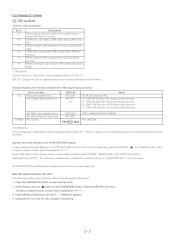
... Indicator Rear panel 1. FM 75 Ohms Antenna Terminal 4. CD Pause Indicator 4. FM Stereo Receiving Indicator 12. Power On/Stand-by Button 4. CD Play or Repeat, Tape Play Button 17. Volume Control 10 22. Tape (1 2) Button 26. Extra Bass Indicator 8. Speaker Terminals 1 234 5 67 12 13 14 15 8 9 10 11 3 4 5 6 1 7 2 1 - 2 Headphone Jack 12. Game/Video Input Jacks 5 13. Disc Number Select Buttons 6 14. CD Direct Play Button 15. CD Track Down or Fast Reverse, Tape 2 Rewind, 3 Tuner Preset Down, Time Down Button 9. CD or Tape Stop Button 20. Game/Video Button...
... Indicator Rear panel 1. FM 75 Ohms Antenna Terminal 4. CD Pause Indicator 4. FM Stereo Receiving Indicator 12. Power On/Stand-by Button 4. CD Play or Repeat, Tape Play Button 17. Volume Control 10 22. Tape (1 2) Button 26. Extra Bass Indicator 8. Speaker Terminals 1 234 5 67 12 13 14 15 8 9 10 11 3 4 5 6 1 7 2 1 - 2 Headphone Jack 12. Game/Video Input Jacks 5 13. Disc Number Select Buttons 6 14. CD Direct Play Button 15. CD Track Down or Fast Reverse, Tape 2 Rewind, 3 Tuner Preset Down, Time Down Button 9. CD or Tape Stop Button 20. Game/Video Button...

Service Manual
Page 12
Remote Control Transmitter 1 2. Disc Number Select Buttons 3. Tape 2 Record Pause Button 9. Game/Video Button 13. CD Play or Repeat, Tape Play Button 19. Equalizer Mode Select Button 8 9 21. Woofer 4. CD Pause Button 8. Tape (1 2) Button 3 12. Clock/Timer Button 4 15. Super Tweeters 5. Memory/Set Button 6. CD Button 11. Power On/Stand-by Button 14. Extra Bass Button 20. Volume Up and Down Buttons 10 11 12 CD-ES900/CD-ES99 13 14 15 16 17 18 19 20 21 CP-ES900/CP-ES99 1. CD Clear/Dimmer Button 5. CD Track Down or Fast...
Remote Control Transmitter 1 2. Disc Number Select Buttons 3. Tape 2 Record Pause Button 9. Game/Video Button 13. CD Play or Repeat, Tape Play Button 19. Equalizer Mode Select Button 8 9 21. Woofer 4. CD Pause Button 8. Tape (1 2) Button 3 12. Clock/Timer Button 4 15. Super Tweeters 5. Memory/Set Button 6. CD Button 11. Power On/Stand-by Button 14. Extra Bass Button 20. Volume Up and Down Buttons 10 11 12 CD-ES900/CD-ES99 13 14 15 16 17 18 19 20 21 CP-ES900/CP-ES99 1. CD Clear/Dimmer Button 5. CD Track Down or Fast...
Service Manual
Page 14
...-CD**'. 'ER-CD**' display will only be checked by mode. 2. Speaker abnormal detection and +B PROTECTION display. In case speaker abnormal detection or +B PROTECTION had occurred, it change to enter stand-by pressing 'POWER', ' ' and 'X-BASS' button. Unplug the AC cord and the unit is moving . Standard Specification of Stereo System Error Message Display Contents Error Contents CD Pickup Mechanism Error. TUNER CD DSP Communication Error. Display will be displayed as "U******". 3. Press the ON/STAND-BY button to CD function, DSP cannot...
...-CD**'. 'ER-CD**' display will only be checked by mode. 2. Speaker abnormal detection and +B PROTECTION display. In case speaker abnormal detection or +B PROTECTION had occurred, it change to enter stand-by pressing 'POWER', ' ' and 'X-BASS' button. Unplug the AC cord and the unit is moving . Standard Specification of Stereo System Error Message Display Contents Error Contents CD Pickup Mechanism Error. TUNER CD DSP Communication Error. Display will be displayed as "U******". 3. Press the ON/STAND-BY button to CD function, DSP cannot...
Service Manual
Page 47
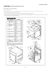
... the power supply plug from the wall outlet before disassembling. After servicing the unit, be sure to rearrange the leads where they need to disassemble the unit. 3. Flat Cable B3) x1 4. Flat Cable D2) x1 3. Flat Wire D4) x1 5. Screw F1) x6 3. Screw G2) x10 3. Screw H1) x2 9 CD Servo PWB 1. Screw E1) x2 2. Hook E3) x2 6 Tape Mechanism 1. Hook...
... the power supply plug from the wall outlet before disassembling. After servicing the unit, be sure to rearrange the leads where they need to disassemble the unit. 3. Flat Cable B3) x1 4. Flat Cable D2) x1 3. Flat Wire D4) x1 5. Screw F1) x6 3. Screw G2) x10 3. Screw H1) x2 9 CD Servo PWB 1. Screw E1) x2 2. Hook E3) x2 6 Tape Mechanism 1. Hook...
Service Manual
Page 56
... deck section, a tape is being played back. ( ) indicates the record state. 4. In the power section, a tape is stopped. • Parts marked with " " ( ) are used : this model are subject to replace these parts with no signal given. 1. Besides, the one measured by Digital Multimeter between such a section and the chassis with specified ones for maintaining the safety and performance of the set . In the CD...
... deck section, a tape is being played back. ( ) indicates the record state. 4. In the power section, a tape is stopped. • Parts marked with " " ( ) are used : this model are subject to replace these parts with no signal given. 1. Besides, the one measured by Digital Multimeter between such a section and the chassis with specified ones for maintaining the safety and performance of the set . In the CD...

Service Manual
Page 73
.../ OPEN/ DIRECT PAUSE SET CLOSE PLAY RD11 RD12 680 820 RD13 1K RD14 1.5K SW712 SW713 SW714 SW715 SW716 DISC 2 DISC 4 DISC 5 DISC 3 DISC 1 TUNER (BAND) RD01 680 CD RD02 820 TAPE GAME/ X-BASS/ VIDEO DEMO RD03 RD04 RD05 1K 1.5K 2.2K RD06 2.7K SW701 SW702 SW703 SW704 SW705 SW706 SW707 POWER ON/STAND-BY CLOCK/ TIMER TUNING UP TUNING DOWN FAST FORWARD/ EQUALIZER FAST REWIND/ PRESET UP PRESET DOWN...
.../ OPEN/ DIRECT PAUSE SET CLOSE PLAY RD11 RD12 680 820 RD13 1K RD14 1.5K SW712 SW713 SW714 SW715 SW716 DISC 2 DISC 4 DISC 5 DISC 3 DISC 1 TUNER (BAND) RD01 680 CD RD02 820 TAPE GAME/ X-BASS/ VIDEO DEMO RD03 RD04 RD05 1K 1.5K 2.2K RD06 2.7K SW701 SW702 SW703 SW704 SW705 SW706 SW707 POWER ON/STAND-BY CLOCK/ TIMER TUNING UP TUNING DOWN FAST FORWARD/ EQUALIZER FAST REWIND/ PRESET UP PRESET DOWN...

Service Manual
Page 76
.... Turn the power off any adjustment make certain that the lens is prohibited by build up of this section does not operate even after the above step is accepted, but playback does not occur. 1) Focus-HF system check 2) Tracking system check 3) Spin system check 4) PLL system check 5) Others 7 - 1 CD optical pickup Lens cleaner disc Parts code UDSKA0004AFZZ HOW TO USE...
.... Turn the power off any adjustment make certain that the lens is prohibited by build up of this section does not operate even after the above step is accepted, but playback does not occur. 1) Focus-HF system check 2) Tracking system check 3) Spin system check 4) PLL system check 5) Others 7 - 1 CD optical pickup Lens cleaner disc Parts code UDSKA0004AFZZ HOW TO USE...

Service Manual
Page 77
...= Main : 100 K Zoom : 2 K =Trigger= Mode : AUTO Type : EDGE CH1 Delay : 0.0 ns Hold off : 0.2 µs Figure 2 7 - 2 Figure 3 Vp-p=1.0 V~1.3 V 0.5 mV/div,0.5 µsec/div Is the laser lit ? Although a CD is inserted and the cover is closed, "NO DISC" is loaded, start playback operation. No Is the disc rotating ? Press the Tray1 CD Eject Button without inserting a disc, and try starting the...
...= Main : 100 K Zoom : 2 K =Trigger= Mode : AUTO Type : EDGE CH1 Delay : 0.0 ns Hold off : 0.2 µs Figure 2 7 - 2 Figure 3 Vp-p=1.0 V~1.3 V 0.5 mV/div,0.5 µsec/div Is the laser lit ? Although a CD is inserted and the cover is closed, "NO DISC" is loaded, start playback operation. No Is the disc rotating ? Press the Tray1 CD Eject Button without inserting a disc, and try starting the...

Service Manual
Page 80
... pur- Output Output Output Output Output Input/Output Input/Output Input/Output Input/Output Output Output Input Input Output - Setting in Reset ZHI AVDD1/2 - - - - - ADAVDD/2 ADAVDD/2 ADAVDD/2 ADAVDD/2 - - - - A signal input pin. D signal input pin. Focus control output pin. D/A output. connected to 0 V. control. RF signal DC level detection LPF capacitor connection pin. D/A output. Spindle control output pin. Controlled by command from the EFM sig- D/A converter L channel output supply pin. Jitter detection capacitor connection pin. Analog GND pin 2. Digital power supply...
... pur- Output Output Output Output Output Input/Output Input/Output Input/Output Input/Output Output Output Input Input Output - Setting in Reset ZHI AVDD1/2 - - - - - ADAVDD/2 ADAVDD/2 ADAVDD/2 ADAVDD/2 - - - - A signal input pin. D signal input pin. Focus control output pin. D/A output. connected to 0 V. control. RF signal DC level detection LPF capacitor connection pin. D/A output. Spindle control output pin. Controlled by command from the EFM sig- D/A converter L channel output supply pin. Jitter detection capacitor connection pin. Analog GND pin 2. Digital power supply...

Service Manual
Page 81
... output DF. D/A converter R channel output supply pin. DAC external clock input pin. Focus ON detection pin. Error flag monitor pin, or sub code Controlled by commands from the microprocessor. Phase comparison output pin 1 to 0 V when unused.) Digital data output Left/Right channel data output pin. Oscillator Oscillator Function Right channel R channel Power supply pin. L Input Input L L L Input Input - - - - - "L" setting: Normal output "H" setting: Nch open ) terminal which is first applied. Left/Right clock input pin. (Must be connect...
... output DF. D/A converter R channel output supply pin. DAC external clock input pin. Focus ON detection pin. Error flag monitor pin, or sub code Controlled by commands from the microprocessor. Phase comparison output pin 1 to 0 V when unused.) Digital data output Left/Right channel data output pin. Oscillator Oscillator Function Right channel R channel Power supply pin. L Input Input L L L Input Input - - - - - "L" setting: Normal output "H" setting: Nch open ) terminal which is first applied. Left/Right clock input pin. (Must be connect...

Service Manual
Page 86
... MIC SW KARA_LATCH NO USE Input/Output Input Output Output Output Output Output Input Output Output Input Output Input - - Tape record bias control. Tape T1/T2 control. Main clock output 4.19 MHz. CD chip enable. Tape 2 solenoid control. Illumination LED. Open. Tape Fool Proof A & B SW. Timer LED control. Output Output Output Output Output Input Output Output Output Input Input Output Input Input Input Input Input Output Input Output Output Function Power supply 5 V. -20dB Attenuator. Volume jog input. Tape 1 solenoid control. Speaker relay control. CE...
... MIC SW KARA_LATCH NO USE Input/Output Input Output Output Output Output Output Input Output Output Input Output Input - - Tape record bias control. Tape T1/T2 control. Main clock output 4.19 MHz. CD chip enable. Tape 2 solenoid control. Illumination LED. Open. Tape Fool Proof A & B SW. Timer LED control. Output Output Output Output Output Input Output Output Output Input Input Output Input Input Input Input Input Output Input Output Output Function Power supply 5 V. -20dB Attenuator. Volume jog input. Tape 1 solenoid control. Speaker relay control. CE...

Service Manual
Page 94
... Switch,Key Type [Equalizer] AC Switch,Key Type [Fast Forward/Preset Up] AC Switch,Key Type [Tuner (Band)] AC Switch,Key Type [CD] AC Switch,Key Type [Tape] AC Switch,Key Type [Game/Video] AC Switch,Key Type [X-Bass/Demo] AC Switch,Key Type [Play/Repeat] AC Switch,Key Type [Stop] AC Switch,Key Type [Rec/Pause] AC Switch,Key Type [Memory/Set] AC Switch,Key Type [Open/Close] AC Switch,Key Type [Direct Play...
... Switch,Key Type [Equalizer] AC Switch,Key Type [Fast Forward/Preset Up] AC Switch,Key Type [Tuner (Band)] AC Switch,Key Type [CD] AC Switch,Key Type [Tape] AC Switch,Key Type [Game/Video] AC Switch,Key Type [X-Bass/Demo] AC Switch,Key Type [Play/Repeat] AC Switch,Key Type [Stop] AC Switch,Key Type [Rec/Pause] AC Switch,Key Type [Memory/Set] AC Switch,Key Type [Open/Close] AC Switch,Key Type [Direct Play...
Service Manual
Page 96
... J LX-JZ0036AWFD J Belt,FF/REW [Tape 2] Head Plate Block [Tape 1] AE Panel,Edge Light AC Lug Wire AD Knob,Volume AL Cover,Volume Knob AE Sheet,Edge Light AA Spring,Ring AR Chassis,Main AP Rear Panel,A AA Nylon Band AM AC Power Supply Cord AD Bushing,AC Power Supply Cord AD Rotary Fan AE Bracket,Fan Support A AB Holder,Fuse AV Heat Sink AD Holder...
... J LX-JZ0036AWFD J Belt,FF/REW [Tape 2] Head Plate Block [Tape 1] AE Panel,Edge Light AC Lug Wire AD Knob,Volume AL Cover,Volume Knob AE Sheet,Edge Light AA Spring,Ring AR Chassis,Main AP Rear Panel,A AA Nylon Band AM AC Power Supply Cord AD Bushing,AC Power Supply Cord AD Rotary Fan AE Bracket,Fan Support A AB Holder,Fuse AV Heat Sink AD Holder...


