

Service Manual
Page 1
Illustration: CD-E700/CD-E77 CD-E700/CD-E77 SERVICE MANUAL No. ONLY) ...2 SPECIFICATIONS ...3 NAMES OF PARTS ...4 DISASSEMBLY ...6 REMOVING AND REINSTALLING THE MAIN PARTS ...9 ADJUSTMENT ...10 NOTES ON SCHEMATIC DIAGRAM ...14 TYPES OF TRANSISTOR AND LED ...14 BLOCK DIAGRAM ...15 SCHEMATIC DIAGRAM / WIRING SIDE OF P.W.BOARD 18 VOLTAGE ...35 WAVEFORMS OF CD CIRCUIT ...36 TROUBLESHOOTING ...37 FUNCTION TABLE OF IC ...41 FL DISPLAY ...47 REPLACEMENT PARTS LIST/EXPLODED VIEW PACKING OF THE SET (FOR U.S.A. The contents...
Illustration: CD-E700/CD-E77 CD-E700/CD-E77 SERVICE MANUAL No. ONLY) ...2 SPECIFICATIONS ...3 NAMES OF PARTS ...4 DISASSEMBLY ...6 REMOVING AND REINSTALLING THE MAIN PARTS ...9 ADJUSTMENT ...10 NOTES ON SCHEMATIC DIAGRAM ...14 TYPES OF TRANSISTOR AND LED ...14 BLOCK DIAGRAM ...15 SCHEMATIC DIAGRAM / WIRING SIDE OF P.W.BOARD 18 VOLTAGE ...35 WAVEFORMS OF CD CIRCUIT ...36 TROUBLESHOOTING ...37 FUNCTION TABLE OF IC ...41 FL DISPLAY ...47 REPLACEMENT PARTS LIST/EXPLODED VIEW PACKING OF THE SET (FOR U.S.A. The contents...

Service Manual
Page 2
... user, perform the following manner. * Plug the AC line cord directly into a 120 volt AC outlet. * Using two clip leads, connect a 1.5 kohm, 10 watt resistor paralleled by a 0.15 µF capacitor in the following safety checks. 1. VTVM AC SCALE 1.5 kohms 10 W TO EXPOSED METAL PARTS 0.15 µF TEST PROBE CONNECT TO KNOWN EARTH GROUND All check must be repeated with 1000 ohm...
... user, perform the following manner. * Plug the AC line cord directly into a 120 volt AC outlet. * Using two clip leads, connect a 1.5 kohm, 10 watt resistor paralleled by a 0.15 µF capacitor in the following safety checks. 1. VTVM AC SCALE 1.5 kohms 10 W TO EXPOSED METAL PARTS 0.15 µF TEST PROBE CONNECT TO KNOWN EARTH GROUND All check must be repeated with 1000 ohm...

Service Manual
Page 3
....1 lbs. (7.3 kg) Amplifier Output power Output terminals Input terminals 125 watts minimum RMS per channel into 6 ohms from 60 Hz to 20 kHz, 10% total harmonic distortion Speakers: 6 ohms Headphones: 16 - 50 ohms (recommended: 32 ohms) Video/Auxiliary (audio signal): 500 mV/47 k ohms CD player Type Signal readout D/A converter Frequency response Dynamic range 3-disc multi-play compact disc player Non-contact, 3-beam semiconductor laser pickup 1-bit D/A converter 20 - 20,000 Hz 90 dB (1 kHz) Tuner Frequency range FM: 87...
....1 lbs. (7.3 kg) Amplifier Output power Output terminals Input terminals 125 watts minimum RMS per channel into 6 ohms from 60 Hz to 20 kHz, 10% total harmonic distortion Speakers: 6 ohms Headphones: 16 - 50 ohms (recommended: 32 ohms) Video/Auxiliary (audio signal): 500 mV/47 k ohms CD player Type Signal readout D/A converter Frequency response Dynamic range 3-disc multi-play compact disc player Non-contact, 3-beam semiconductor laser pickup 1-bit D/A converter 20 - 20,000 Hz 90 dB (1 kHz) Tuner Frequency range FM: 87...

Service Manual
Page 4
... Button 1 4. Tuning and Time Up Button 3 8. Tape 1 Cassette Compartment 6 12. CD or Tape Stop Button 21. Tape 2 Record Indicator 5. FM Stereo Receiving Indicator 7. Timer Play Indicator 8. CD Play Indicator 11. Tape Play Indicator 13. Video/Auxiliary (Audio Signal) Input Jacks 5. Volume Control 15. Tuner (Band) Button 23. CD Pause Indicator 2. Extra Bass Indicator 3. CD-E700/CD-E77 CD-E700/CD-E77 Front panel NAMES OF PARTS 1. Power On/Stand-by Button 5. FM Stereo Mode Indicator 6. AC Power Cord 3. Disc Tray 2. Headphone Jack 10. CD Button 11 19. CD...
... Button 1 4. Tuning and Time Up Button 3 8. Tape 1 Cassette Compartment 6 12. CD or Tape Stop Button 21. Tape 2 Record Indicator 5. FM Stereo Receiving Indicator 7. Timer Play Indicator 8. CD Play Indicator 11. Tape Play Indicator 13. Video/Auxiliary (Audio Signal) Input Jacks 5. Volume Control 15. Tuner (Band) Button 23. CD Pause Indicator 2. Extra Bass Indicator 3. CD-E700/CD-E77 CD-E700/CD-E77 Front panel NAMES OF PARTS 1. Power On/Stand-by Button 5. FM Stereo Mode Indicator 6. AC Power Cord 3. Disc Tray 2. Headphone Jack 10. CD Button 11 19. CD...
Service Manual
Page 5
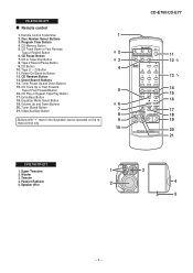
CD Memory Button 5. Direct Search Buttons 14. Woofer 3. CD Random Button 13. Tuner (Band) Button 21. Super Tweeters 2. Remote Control Transmitter 1 2. Equalizer Mode Select Button 19. Passive Radiator 5. Power On/Stand-by Button 12. Speaker Wire 1 3 2 4 5 - 5 - CD Pause Button 7. Tape 2 Record Pause Button 9. CD Button 10. Tape (1 2) Button 4 11. Tuner Preset Up and Down Buttons 15. Video/Auxiliary Button 7 8 Buttons with " " mark in the illustration can be operated on the re- 9 mote control only. 10 CD-E700/CD-E77 11 12 13 14 15 16 17 ...
CD Memory Button 5. Direct Search Buttons 14. Woofer 3. CD Random Button 13. Tuner (Band) Button 21. Super Tweeters 2. Remote Control Transmitter 1 2. Equalizer Mode Select Button 19. Passive Radiator 5. Power On/Stand-by Button 12. Speaker Wire 1 3 2 4 5 - 5 - CD Pause Button 7. Tape 2 Record Pause Button 9. CD Button 10. Tape (1 2) Button 4 11. Tuner Preset Up and Down Buttons 15. Video/Auxiliary Button 7 8 Buttons with " " mark in the illustration can be operated on the re- 9 mote control only. 10 CD-E700/CD-E77 11 12 13 14 15 16 17 ...

Service Manual
Page 6
... 8 Tape Mechanism 1. Screw M1) x2 7-5 (Note 2) 2. Hook N1) x2 7-6 2. Hook N2) x2 Note 1: How to open the disc tray, take out the CD tray cover, and close. (Note 1) 2. Turn on the power supply, .. 6-2 CD Player Unit open the changer manually. (Fig. 6-3) 1. Screw E1) x3 2. Screw G2) x10 3. Flat Cable E3) x1 4. Socket M3) x4 13 CD Mechanism 1. Hook F2) x2 3. Flat Wire F3) x1 7 Display...
... 8 Tape Mechanism 1. Screw M1) x2 7-5 (Note 2) 2. Hook N1) x2 7-6 2. Hook N2) x2 Note 1: How to open the disc tray, take out the CD tray cover, and close. (Note 1) 2. Turn on the power supply, .. 6-2 CD Player Unit open the changer manually. (Fig. 6-3) 1. Screw E1) x3 2. Screw G2) x10 3. Flat Cable E3) x1 4. Socket M3) x4 13 CD Mechanism 1. Hook F2) x2 3. Flat Wire F3) x1 7 Display...
Service Manual
Page 10
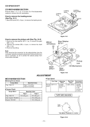
... x 2 pcs., to remove the pickup unit (See Fig. 10-2) 1. Bend the hooks (A1) x 5 pcs., to remove the gear (B2) x 1 pc. 2. Specified Instrument Value Connection 3,000 ± 30 Hz Speaker Terminal (Load resistance: 6 ohms) TAPE MECHANISM Tape Motor - 10 - Remove the stop washer (B1) x 1 pc., to remove the...70 to 180 g.cm • Tape Speed Test Tape Normal MTT-111 speed Adjusting Point Variable Resistor in motor Figure 10-3 CD-E700/CD-E77 CD MECHANISM SECTION Perform steps 1, 2, 3, 10, 11,12 and 13 of connector so as to protect the optical pickup from the connector wrap the ...
... x 2 pcs., to remove the pickup unit (See Fig. 10-2) 1. Bend the hooks (A1) x 5 pcs., to remove the gear (B2) x 1 pc. 2. Specified Instrument Value Connection 3,000 ± 30 Hz Speaker Terminal (Load resistance: 6 ohms) TAPE MECHANISM Tape Motor - 10 - Remove the stop washer (B1) x 1 pc., to remove the...70 to 180 g.cm • Tape Speed Test Tape Normal MTT-111 speed Adjusting Point Variable Resistor in motor Figure 10-3 CD-E700/CD-E77 CD MECHANISM SECTION Perform steps 1, 2, 3, 10, 11,12 and 13 of connector so as to protect the optical pickup from the connector wrap the ...

Service Manual
Page 11
... 990 kHz (fL): T303 *1 *1. Input: Antenna Output: TP301 *2. TUNER SECTION fL: Low-range frequency fH: High-range frequency • AM IF/RF Signal generator: 400 Hz, 30%, AM modulated Test Stage Frequency Frequency Setting/ Instrument Display Adjusting Connection Parts AM IF 450 kHz 1,720 kHz T351 *1 AM Band - Each time a disc is not needed when replacing the pickup. Input: Antenna *2. Clamp switch cannot detect 'ON' level for 7 secs. 10* When disc table rotate to target position.
... 990 kHz (fL): T303 *1 *1. Input: Antenna Output: TP301 *2. TUNER SECTION fL: Low-range frequency fH: High-range frequency • AM IF/RF Signal generator: 400 Hz, 30%, AM modulated Test Stage Frequency Frequency Setting/ Instrument Display Adjusting Connection Parts AM IF 450 kHz 1,720 kHz T351 *1 AM Band - Each time a disc is not needed when replacing the pickup. Input: Antenna *2. Clamp switch cannot detect 'ON' level for 7 secs. 10* When disc table rotate to target position.

Service Manual
Page 12
CD-E700/CD-E77 TEST MODE • Setting the test mode Any one of test mode can be appoint directly. Function: -CD test mode. -Enter test mode. Adjustment result automatically will display as follows. + + TEST: CD operation test. FLAT X-BASS - STOP - 12 - key input. Do TOC IL. Laser ON. CD TEST OPEN/CLOSE operation is input into PLAY key, track number can be in STOP mode. Adjustment result automatically will display as below for each 2 sec : a) "FOFF_XX" b) "TOFF_XX" c) "TBAL_XX" d) "TGAN_XX" f) "FGAN_XX" g) "RFLS_XX" key input. IL isn...
CD-E700/CD-E77 TEST MODE • Setting the test mode Any one of test mode can be appoint directly. Function: -CD test mode. -Enter test mode. Adjustment result automatically will display as follows. + + TEST: CD operation test. FLAT X-BASS - STOP - 12 - key input. Do TOC IL. Laser ON. CD TEST OPEN/CLOSE operation is input into PLAY key, track number can be in STOP mode. Adjustment result automatically will display as below for each 2 sec : a) "FOFF_XX" b) "TOFF_XX" c) "TBAL_XX" d) "TGAN_XX" f) "FGAN_XX" g) "RFLS_XX" key input. IL isn...

Service Manual
Page 13
... times. Speaker abnormal detection and +B PROTECTION display In case speaker abnormal detection or +B PROTECTION had been detected for transporting. - 13 - While pressing down the button and the X-Bass/Demo button, press the Power button until "WAIT" "FINISHED" appears. 4. CD-E700/CD-E77 Standard Specification of 'ER-CD**' display 'ER-CD**' will show "S** B**". Display will only be display when CD changer mechanism error had occured, it can be taken after set tapering/parts replacement. 1. DISPLAY 'ER-CD**' 'ER-CD**' (*) 'ER-CD...
... times. Speaker abnormal detection and +B PROTECTION display In case speaker abnormal detection or +B PROTECTION had been detected for transporting. - 13 - While pressing down the button and the X-Bass/Demo button, press the Power button until "WAIT" "FINISHED" appears. 4. CD-E700/CD-E77 Standard Specification of 'ER-CD**' display 'ER-CD**' will show "S** B**". Display will only be display when CD changer mechanism error had occured, it can be taken after set tapering/parts replacement. 1. DISPLAY 'ER-CD**' 'ER-CD**' (*) 'ER-CD...

Service Manual
Page 14
... type (P.P.): Polypropylene type • Schematic diagram and Wiring Side of P.W.Board for this symbol P means pico-farad and the unit of the set . In the tuner section, indicates AM indicates FM stereo 2. NO SW712 SW713 SW714 SW715 SW716 SW717 SW718 SW721 SW722 SW723 SW724 DESCRIPTION TUNER VIDEO/AUX TAPE STOP PLAY FAST FORWARD FAST REWIND X-BASS/DEMO EQUALIZER OPEN/CLOSE DISC SKIP POSITION ON-OFF...
... type (P.P.): Polypropylene type • Schematic diagram and Wiring Side of P.W.Board for this symbol P means pico-farad and the unit of the set . In the tuner section, indicates AM indicates FM stereo 2. NO SW712 SW713 SW714 SW715 SW716 SW717 SW718 SW721 SW722 SW723 SW724 DESCRIPTION TUNER VIDEO/AUX TAPE STOP PLAY FAST FORWARD FAST REWIND X-BASS/DEMO EQUALIZER OPEN/CLOSE DISC SKIP POSITION ON-OFF...
Service Manual
Page 17
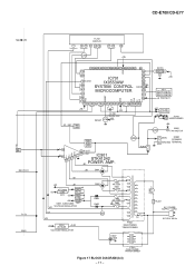
...CD-E700/CD-E77 +B4 B T Q601 Q602 REC/PLAY T1/T2 BIAS FL701 DISPLAY 1 5 12 13 14 19 27 41 45 Q705 +B5 57 56 55 54 53 52 51 50 49 48 47 46 45 44 43 42 40 VDD 70 39 - - 85 79 VLOAD 86 91 92 IC701 IX0553AW SYSTEM CONTROL...T.F. Q905 RL914 MAIN SO901 SPEAKER GROUND TERMINAL +B2 D801 VL+ VL- PT801 MAIN POWER TRANSFORMER D842~ D845 RL841 AC POWER SUPPLY CORD AC120 V, 60 Hz PT841 SUB POWER TRANSFORMER Figure 17 BLOCK DIAGRAM (3/3) - 17 - D905 D906 RX701 1 REMOTE SENSOR 3 2 +B5 KEY SW701-SW707 SW711-SW718 SW721-SW724 +B PROTECT +B7 TO CD SECTION +B3 JK701 HEADPHONES ...
...CD-E700/CD-E77 +B4 B T Q601 Q602 REC/PLAY T1/T2 BIAS FL701 DISPLAY 1 5 12 13 14 19 27 41 45 Q705 +B5 57 56 55 54 53 52 51 50 49 48 47 46 45 44 43 42 40 VDD 70 39 - - 85 79 VLOAD 86 91 92 IC701 IX0553AW SYSTEM CONTROL...T.F. Q905 RL914 MAIN SO901 SPEAKER GROUND TERMINAL +B2 D801 VL+ VL- PT801 MAIN POWER TRANSFORMER D842~ D845 RL841 AC POWER SUPPLY CORD AC120 V, 60 Hz PT841 SUB POWER TRANSFORMER Figure 17 BLOCK DIAGRAM (3/3) - 17 - D905 D906 RX701 1 REMOTE SENSOR 3 2 +B5 KEY SW701-SW707 SW711-SW718 SW721-SW724 +B PROTECT +B7 TO CD SECTION +B3 JK701 HEADPHONES ...
Service Manual
Page 37
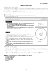
... the trouble shooting instructions. When this happening then drink and / or rinse with the DSP). 2. Gently clean the lens with the bare hand. 1. CD optical pickup Lens cleaner disc Parts code UDSKA0004AFZZ HOW TO USE 1. Using the ...displayed. (1) Check the power to IC1 (LC78646E), the presence of the clock signal (16.933 MHz) and the status of the RESET terminal (pin 66 on the CD cleaner disc which has the mark next to turn, press the stop . Cleaner disc When a CD cannot be effective for about 20 seconds and the CD player will automatically stop button. Pressing the CD operation...
... the trouble shooting instructions. When this happening then drink and / or rinse with the DSP). 2. Gently clean the lens with the bare hand. 1. CD optical pickup Lens cleaner disc Parts code UDSKA0004AFZZ HOW TO USE 1. Using the ...displayed. (1) Check the power to IC1 (LC78646E), the presence of the clock signal (16.933 MHz) and the status of the RESET terminal (pin 66 on the CD cleaner disc which has the mark next to turn, press the stop . Cleaner disc When a CD cannot be effective for about 20 seconds and the CD player will automatically stop button. Pressing the CD operation...
Service Manual
Page 41
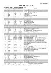
... which is not connected to 0 V. Defect terminal. The status changes to 0 V, or set them as input terminals and connect General-purpose I/O terminal 6 or to "H" when the sync signal detected in Reset SLCO Output - Must be connected to 0 V. EFMIN Input - L L - Control output. E signal input terminal. TE signal monitor terminal. D/A output. Terminal functions are identified. When not used , set by commands from the microcomputer. Internal signal monitor terminal 4. Digital system power terminal. Digital OUT output terminal. (EIAJ format...
... which is not connected to 0 V. Defect terminal. The status changes to 0 V, or set them as input terminals and connect General-purpose I/O terminal 6 or to "H" when the sync signal detected in Reset SLCO Output - Must be connected to 0 V. EFMIN Input - L L - Control output. E signal input terminal. TE signal monitor terminal. D/A output. Terminal functions are identified. When not used , set by commands from the microcomputer. Internal signal monitor terminal 4. Digital system power terminal. Digital OUT output terminal. (EIAJ format...
Service Manual
Page 42
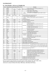
...2. and open drain output.) *WRQ Output H Interruption signal output. *RES Input - VCO frequency range adjustment port. - FSX/16MIN Input/Output Input 7.35 kHz Synchronization signal monitor port. Must be connected to the outside. Word clock input port. (If this port does not use , must be connect to 0 V, or set LOW after first applied power on. VSS - - Internal VCO control phase comparator output port 2. Output Input - Chip enable signal input port. Power supply for digital circuit. output terminal 7. Input Input Input - - - Must be...
...2. and open drain output.) *WRQ Output H Interruption signal output. *RES Input - VCO frequency range adjustment port. - FSX/16MIN Input/Output Input 7.35 kHz Synchronization signal monitor port. Must be connected to the outside. Word clock input port. (If this port does not use , must be connect to 0 V, or set LOW after first applied power on. VSS - - Internal VCO control phase comparator output port 2. Output Input - Chip enable signal input port. Power supply for digital circuit. output terminal 7. Input Input Input - - - Must be...
Service Manual
Page 45
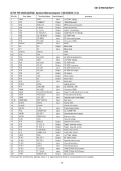
... P125 SP_RLY JOG 1 Output Input Speaker relay control. Tape record bias. 5 P34 T_T1/T2 Output Tape T1/T2 change. 6 P33 T_REC/PLY Output Tape REC/PLAY change. 7 P32 CD_RESOUT Output CD DSP reset. 8 P31 CD WRQ Input CD write read request.. 9* P30 10 RESET NO USE RESET Input Input Connect to GND. Open 15 P04 CD_DRF Input CD DRF level detection. 16 VDD VDD Input (+) Power supply. 17 P27 18 P26 CD_CLK CD_DI Output Output CD DSP clock. Analog ground. 26 P17 D.NO SW Input CD DISC No.
... P125 SP_RLY JOG 1 Output Input Speaker relay control. Tape record bias. 5 P34 T_T1/T2 Output Tape T1/T2 change. 6 P33 T_REC/PLY Output Tape REC/PLAY change. 7 P32 CD_RESOUT Output CD DSP reset. 8 P31 CD WRQ Input CD write read request.. 9* P30 10 RESET NO USE RESET Input Input Connect to GND. Open 15 P04 CD_DRF Input CD DRF level detection. 16 VDD VDD Input (+) Power supply. 17 P27 18 P26 CD_CLK CD_DI Output Output CD DSP clock. Analog ground. 26 P17 D.NO SW Input CD DISC No.

Service Manual
Page 49
... type (without lead wire) VR • • CZ Square type (without lead wire) VC J .. REF. The 13th character represents error. ("J" ±5%, "F" ±1%, "D" ±0.5%.) If there are ±5% carbon-film type. MODEL NUMBER 2. PARTS GUIDE CD-E700/CD-E77 MINI COMPONENT SYSTEM MODEL CD-E700 CD-E700 Mini Component System consisting of CD-E77 (main unit) and CP-E77 (speaker system). MINI COMPONENT SYSTEM MODEL CD-E77 CD-E77 Mini Component System consisting of CD-E700 (main unit) and CP-E700 (speaker system).
... type (without lead wire) VR • • CZ Square type (without lead wire) VC J .. REF. The 13th character represents error. ("J" ±5%, "F" ±1%, "D" ±0.5%.) If there are ±5% carbon-film type. MODEL NUMBER 2. PARTS GUIDE CD-E700/CD-E77 MINI COMPONENT SYSTEM MODEL CD-E700 CD-E700 Mini Component System consisting of CD-E77 (main unit) and CP-E77 (speaker system). MINI COMPONENT SYSTEM MODEL CD-E77 CD-E77 Mini Component System consisting of CD-E700 (main unit) and CP-E700 (speaker system).

Service Manual
Page 53
... Switch,Key Type [Clock] AC Switch,Key Type [CD] AC Switch,Key Type [Tuner] AC Switch,Key Type [Video/AUX] AC Switch,Key Type [Tape] AC Switch,Key Type [Stop] AC Switch,Key Type [Play] AC Switch,Key Type [Fast Forward] AC Switch,Key Type [Fast Rewind] AC Switch,Key Type [X-Bass/Demo] AC Switch,Key Type [Equalizer] AC Switch,Key Type [Open/Close] AC Switch,Key Type [Disc Skip] AB Holder,Flat Wire...
... Switch,Key Type [Clock] AC Switch,Key Type [CD] AC Switch,Key Type [Tuner] AC Switch,Key Type [Video/AUX] AC Switch,Key Type [Tape] AC Switch,Key Type [Stop] AC Switch,Key Type [Play] AC Switch,Key Type [Fast Forward] AC Switch,Key Type [Fast Rewind] AC Switch,Key Type [X-Bass/Demo] AC Switch,Key Type [Equalizer] AC Switch,Key Type [Open/Close] AC Switch,Key Type [Disc Skip] AB Holder,Flat Wire...

Service Manual
Page 54
... Loop Antenna AE Operation Manual [Except for Canada] BD Tape Mechanism Ass'y Head Plate Block [Tape 2] Motor with Pulley [Tape] -- Tape Mechanism OTHER SERVICE PART UDSKA0004AFZZ J AZ CD Pickup Lens Cleaner - 5 - PARTS CODE PRICE RANK DESCRIPTION JKNBZ0922AWSA J JKNBZ0922AWSB J JKNBZ0923AWSA J JKNBZ0924AWSA J JKNBZ0925AWSA J JKNBZ0926AWSA J GCOVA1460AWSA J GCOVA1351AWSA J MSPRD0151AWFJ J MSPRD0152AWFJ J MLIFP0008AWZZ J HBDGB1007AWSA J 92LCAB3838BASY J 92LCAB3839BASY J ---- Side Panel,Right (Not Replacement Item) AB Cushion,Leg AM Loading Tray AT Top Cabinet [CD-E700...
... Loop Antenna AE Operation Manual [Except for Canada] BD Tape Mechanism Ass'y Head Plate Block [Tape 2] Motor with Pulley [Tape] -- Tape Mechanism OTHER SERVICE PART UDSKA0004AFZZ J AZ CD Pickup Lens Cleaner - 5 - PARTS CODE PRICE RANK DESCRIPTION JKNBZ0922AWSA J JKNBZ0922AWSB J JKNBZ0923AWSA J JKNBZ0924AWSA J JKNBZ0925AWSA J JKNBZ0926AWSA J GCOVA1460AWSA J GCOVA1351AWSA J MSPRD0151AWFJ J MSPRD0152AWFJ J MLIFP0008AWZZ J HBDGB1007AWSA J 92LCAB3838BASY J 92LCAB3839BASY J ---- Side Panel,Right (Not Replacement Item) AB Cushion,Leg AM Loading Tray AT Top Cabinet [CD-E700...

Service Manual
Page 60
...] Featurel Label [Tape2] 92LBAG1460C1 Polyethylene Bag, Accessories AM/FM Loop Antenna Operation Manual Quick Guide Remote Control BOTTOM B A B REAR REAR SPAKC1547AWZZ [CD-E700] SPAKC1554AWZZ [CD-E77] Packing Case Not Replacement Item COPYRIGHT © 2002 BY SHARP CORPORATION ALL RIGHTS RESERVED. SPAKZ1033AWZZ Protection Sheet UNIT SPAKP0032AWZZ Polyethylene Bag,Unit CD-E700/CD-E77 SPAKA0431AWZZ Packing Add. No part of this publication may be reproduced, stored in a retrieval system, or...
...] Featurel Label [Tape2] 92LBAG1460C1 Polyethylene Bag, Accessories AM/FM Loop Antenna Operation Manual Quick Guide Remote Control BOTTOM B A B REAR REAR SPAKC1547AWZZ [CD-E700] SPAKC1554AWZZ [CD-E77] Packing Case Not Replacement Item COPYRIGHT © 2002 BY SHARP CORPORATION ALL RIGHTS RESERVED. SPAKZ1033AWZZ Protection Sheet UNIT SPAKP0032AWZZ Polyethylene Bag,Unit CD-E700/CD-E77 SPAKA0431AWZZ Packing Add. No part of this publication may be reproduced, stored in a retrieval system, or...


