
Sharp CD-E700 Support Question
Sharp CD-E700 Support Question
Find answers below for this question about Sharp CD-E700.Need a Sharp CD-E700 manual? We have 1 online manual for this item!
Question posted by Anonymous-158512 on April 22nd, 2016
The Light Stays On
I shut off the system but the display light stays on. How to I get it to turn off
Current Answers
Related Sharp CD-E700 Manual Pages
Service Manual - Page 1

... IC ...41 FL DISPLAY ...47 REPLACEMENT PARTS LIST/EXPLODED VIEW PACKING OF THE SET (FOR U.S.A. The contents are subject to be used for after sales service only. MINI COMPONENT SYSTEM
MODEL CD-E77
CD-E77 Mini Component System consisting of CD-E77 (main unit) and CP-E77 (speaker system).
• In the interests of CD-E700 (main unit...
Service Manual - Page 2

....
To be sure that hardware is excessive and indicates a potential shock hazard which must be corrected before returning the audio product to 0.2 milliamp. Any reading of 0.3 volt RMS (this corresponds to the owner.
- 2 - CD-E700/CD-E77
IMPORTANT SERVICE NOTES (FOR U.S.A. Inspect all exposed metal cabinet parts and a known earth ground, such as insulating...
Service Manual - Page 3

...277 mm) Height: 13" (330 mm) Depth: 10-3/4" (273 mm) 9.9 lbs. (4.5 kg)/each
CD-E700/CD-E77 (For Canada)
General
Power source Power consumption Dimensions
Weight
AC 120 V, 60 Hz 110 W
Width:... ohms
Headphones: 16 - 50 ohms (recommended: 32 ohms)
Video/Auxiliary (audio signal): 500 mV/47 k ohms
CD player
Type Signal readout
D/A converter Frequency response Dynamic range
3-disc multi-play compact...
Service Manual - Page 4

... Button 25. FM/AM Loop Antenna Jack
1
4. Timer/Sleep Button 7. AC Power Cord 3. Timer Play Indicator 8. CD or Tape Stop Button
21. CD Pause Indicator 2. Extra Bass Indicator 3. Tape 1 Cassette Compartment
6
12. CD Button
11
19. CD-E700/CD-E77
CD-E700/CD-E77
Front panel
NAMES OF PARTS
1. Equalizer Mode Select Button
7
13. Speaker Terminals
Note:
This product...
Service Manual - Page 5
... Down or Fast Reverse,
Tape 2 Rewind Button
2
6. Direct Search Buttons
14. CD Track Up or Fast Forward,
Tape 2 Fast Forward Button
5
16. CD Memory Button
5. CD Random Button
13. CD-E700/CD-E77
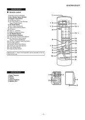
Remote control
1. Remote Control Transmitter
1
2. Program Clear Button
4. CD or Tape Stop Button
3
8. CD Play or Repeat, Tape Play Button
17. Volume Up and Down...
Service Manual - Page 6

...A1)x2 ø3x12mm
CD-E700/CD-E77
STEP REMOVAL
PROCEDURE
FIGURE
1 Top Cabinet
1. Flat Wire F3) x1
7 Display PWB
1. Hook K1) x2 7-3 2. Socket M3) x4
13 CD Mechanism 1.
Be careful ... 7-2 2. Screw M1) x2 7-5
(Note 2)
2. Hook N1) x2 7-6 2. In this state, turn fully the lock lever in the arrow direction through
the hole on static electricity of the unit. 2. After ...
Service Manual - Page 8

...;4x16mm
Screwdriver
Driver should be pried away from Speaker Box. Screw A1) x4 8-1 2. Screw B2) x4 8-3
3 Tweeter
1. Side Panel A2) x1 3. Front Panel B1) x1 8-2 2.
CD-E700/CD-E77
CP-E700/CP-E77
STEP REMOVAL
PROCEDURE
FIGURE
1 Passive Radiator 1.
Service Manual - Page 9

.... 9-2)
1.
Remove the FF/REW belt (D2) x 1 pc.
(B1)x2 Ø2x9mm
Figure 9-2
How to remove the tape mechanism. Remove the FF/REW belt (E2) x 1 pc. CD-E700/CD-E77
REMOVING AND REINSTALLING THE MAIN PARTS
TAPE MECHANISM SECTION
TAPE 2
Perform steps 1 to 6 and 8 of the disassembly method to remove the belt (TAPE 1) (See...
Service Manual - Page 10
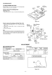
...B3) x 2 pcs., to remove the gear (B2) x 1 pc.
2.
CD-E700/CD-E77
CD MECHANISM SECTION
Perform steps 1, 2, 3, 10, 11,12 and 13 of connector ...
3.
Figure 10-1
(B3)x2 ø2.6x6mm
Stop Washer (B1)x1
Shaft (B4)x1
ADJUSTMENT
Pickup Unit
Gear (B2)x1
CD Mechanism
Figure 10-2
MECHANISM SECTION
• Driving Force Check
Torque Meter
Specified Value
Play: TW-2111
Tape 1: Over 80 g...
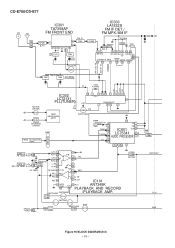
Service Manual - Page 11

...**' display. 'ER-CD**' display will be combined freely. Input: Antenna
Output: TP301
MAIN PWB
CNP301 AM/FM LOOP
ANTENNA IC301
FM BAND COVERAGE fL
R381 TP301
T301
1 T303
T302 FM IF
FM RF L312
T351 AM IF
T306
AM TRACKING fL
AM BAND COVERAGE fL
R356 TP302
Figure 11-1 ADJUSTMENT POINTS
CD-E700/CD-E77
CD SECTION...
Service Manual - Page 12

...for each 2 sec : a) "FOFF_XX" b) "TOFF_XX" c) "TBAL_XX" d) "TGAN_XX" f) "FGAN_XX" g) "RFLS_XX"
key input.
key input. Adjustment result automatically will display as follows. + + TEST: CD operation test. Adjustment result automatically will display as below . STOP
- 12 -
CD-E700/CD-E77
TEST MODE
• Setting the test mode Any one of test mode can be appoint directly. Function...
Service Manual - Page 13

CD-E700/CD-E77
Standard Specification of 'ER-CD**' display 'ER-CD**' will only be display when CD changer mechanism error had occured, it can be check by pressing 'POWER', 'VIDEO' and 'XBASS' key twice.
While pressing down the button and the X-Bass/Demo button, press the Power button until "WAIT"
"FINISHED" appears.
4. Speaker abnormal detection and +B PROTECTION display In...
Service Manual - Page 14

... NUMBER PICKUP IN POWER MEMORY SET REC/PAUSE TUNING DOWN TUNING UP TIMER/SLEEP CLOCK CD
POSITION ON-OFF ON-OFF ON-OFF ON-OFF ON-OFF ON-OFF ON-OFF ...In the power section, a tape is being played back.
5.
In the CD section, the CD is stopped.
• Parts marked with no signal given.
1. CD-E700/CD-E77
NOTES ON SCHEMATIC DIAGRAM
• Resistor: To differentiate the units of resistors...
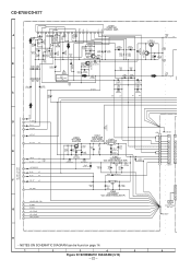
Service Manual - Page 16
...NF
IC101
12 NOR/ HIGH
T1/T2 10 ALC
AN7345K
15 19 PLAYBACK AND RECORD
SWITCHING SWITCHING
/PLAYBACK AMP. CD-E700/CD-E77
FM OSC AM OSC IN AM RF IN STEREO CE DI CLK DO
IC303
IC301
LA1832S
TA7358AP
FM IF ...
DI 1
R
R 16
CE 2
TAPE L 10
IC601 CLK 24
R 15
TUNER L 11 R 14
LC75341 AUDIO PROCESSOR
21 R 4L
CD L 12 R 13
7 8 17 18 3
-20dB ATT Q601 Q602
TAPE 1 L-CH PB HEAD R-CH
REC P.B.
Service Manual - Page 18

...2
3
4
5
6
Figure 18 SCHEMATIC DIAGRAM (1/10) - 18 - ALC Nor/CrO2
ALC RIPPLE Vcc
CD-E700/CD-E77
CNS601 1 R-CH
BI601 1
2
A_GND
A
2
3
L-CH 3
4
CD_GND
4
5
CD_+B
+B
5
6
6
7
+B
D_GND
7
8...KTC3199 GR
R612 390
R L
R601 1K
R602 1K
C652 220P C651 220P
IC601
LC75341
C653 220P
AUDIO PROCESSOR
C601 220/16
R605 10K
C609 1/50
R607 3.9K
C607 0.12 (ML) C611 0.0022...
Service Manual - Page 22
...5V
+B
A_5V
+B
11
F
SW_5V
+B
26
CD_GND 13
AGND(AUDIO PRO) 21
19
M_GND
D_GND
G
24
CD_D_GND 17
CD_A_GND 18...
2
2
3
3
4
4
5
5
6
6
7
7
8
8
9
9
10
10
CNS801
1 2 3 4 5 6 FW701 FROM DISPLAY PWB P25 12-F
CHASSIS
H
• NOTES ON SCHEMATIC DIAGRAM can be found on page 14.
1
2
3
4
5
6
Figure 22 SCHEMATIC ...CD-E700/CD-E77
+
IC901
-
- VL+ VH+
GND VH-
Service Manual - Page 30

CD-E700/CD-E77
A
DISPLAY PWB-A2
BI701 R795 R783 R704 R703 R706
LED704 BI704 C717
LED B PWB-A5
B
1 1 2
2 CNS704
SW722 EQUALIZER
SW721 X-BASS/DEMO RD19
RD20
3
1 2
RX701
C
12
C701
C702
CNP704
CNS701
11
D
TO CD SERVO PWB P32 3-A CNP6
10 9 8 7 6 5 4 3 2
1
WH
YL WH
YL WH YL WH YL WH
RD
JOG701 JOG VOLUME
FW701
1 Q709...
Service Manual - Page 49

... represents error.
("J" ±5%, "F" ±1%, "D" ±0.5%.)
If there are ±5% carbon-film type. MINI COMPONENT SYSTEM
MODEL CD-E77
CD-E77 Mini Component System consisting of CD-E700 (main unit) and CP-E700 (speaker system).
PARTS GUIDE
CD-E700/CD-E77
MINI COMPONENT SYSTEM
MODEL CD-E700
CD-E700 Mini Component System consisting of CD-E77 (main unit) and CP-E77 (speaker system).
Service Manual - Page 54

...Tape 2] AS Remote Control
AK Battery Lid,Remote Control
P.W.B. Main/Display/Headphones/LED A/LED B (Combined Ass'y)
-- CD Servo AD CD Motor (PWB Only) AD CD Loading Motor (PWB Only) --
CD-E700/CD-E77
NO.
201- 8 201- 8 201- 9 201-10...80mm AB Roller
AD Bracket,Heat Sink
AF Panel,Edge Light
AC Holder,Edge Light
AK Knob,Volume AD Sheet,Edge Light
AC Plate,Support AA Screw,ø3×10mm AA ...
Service Manual - Page 60

SPAKZ1033AWZZ Protection Sheet
UNIT
SPAKP0032AWZZ Polyethylene Bag,Unit
CD-E700/CD-E77
SPAKA0431AWZZ Packing Add. No part of this publication may be reproduced, stored in a retrieval system, or transmitted in Japan
A0212-1459DS•HA•M
SC • SL
SHARP CORPORATION AV Systems Group Audio Systems Division Higashihiroshima, Hiroshima 739-0192, Japan
Printed in any...
Similar Questions

Sharp Cd-dk890n Shuts Off By Itself
when playing cd's the unit shuts off by itself after running for about 1 min 50 seconds also when vo...
when playing cd's the unit shuts off by itself after running for about 1 min 50 seconds also when vo...
(Posted by rbell1248 3 years ago)

Aux Input.
Hi there! My mother in law has a Sharp CD-E700 stereo system and wants to know how to connect her ph...
Hi there! My mother in law has a Sharp CD-E700 stereo system and wants to know how to connect her ph...
(Posted by Alyssatoppins 6 years ago)

Has An Error Code Of Cd-11 How Do I Fix Cd Is Stuck And Won't Turn Or Open An Y
Can you assist?
Can you assist?
(Posted by sixgunsadie 9 years ago)

Red Light Wont Turn On
I just set up my new soundbar and it worked great for about four days..Now when it turns on via a sm...
I just set up my new soundbar and it worked great for about four days..Now when it turns on via a sm...
(Posted by PLavin223 10 years ago)

When Power Button Pressed Light A Second Shows Cd And Shuts Off
(Posted by Anonymous-97816 11 years ago)