
Service Manual
Page 1
SHARP CORPORATION This document has been published to replace these parts with " " are subject to change without notice. Be sure to be used for after sales service only. The contents are important for maintaining the safety of the set . SERVICE MANUAL CODE: 00ZARRB1//A1E DIGITAL FULL COLOR COPIER/PRINTER/ MULTIFUNCTIONAL SYSTEM OPTION DUPLEX BYPASS/INVERTER UNIT MODEL AR-RB1 CONTENTS [1] SPECIFICATIONS 1-1 [2] UNPACKING AND INSTALLATION 1-1 [3] INTERIOR CONSTRUCTION 3-1 [4] DESCRIPTION OF OPERATION 4-1 [5] DISASSEMBLY, ASSEMBLY AND...
SHARP CORPORATION This document has been published to replace these parts with " " are subject to change without notice. Be sure to be used for after sales service only. The contents are important for maintaining the safety of the set . SERVICE MANUAL CODE: 00ZARRB1//A1E DIGITAL FULL COLOR COPIER/PRINTER/ MULTIFUNCTIONAL SYSTEM OPTION DUPLEX BYPASS/INVERTER UNIT MODEL AR-RB1 CONTENTS [1] SPECIFICATIONS 1-1 [2] UNPACKING AND INSTALLATION 1-1 [3] INTERIOR CONSTRUCTION 3-1 [4] DESCRIPTION OF OPERATION 4-1 [5] DISASSEMBLY, ASSEMBLY AND...
Service Manual
Page 2
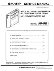
... direction and delivery to duplex unit 3. Power supply 5V, 24V supplied by the dotted sec- Paper feed speed Full color Monochrome 26 sheets/min. (A4 landscape feed) 33 sheets/min. (A4 landscape feed) 8. UNPACKING Accessories Spacer Restraining tape (remove) Spacer Packing case Restraining tape (remove) Note: Never put the reverse bypass module down delivery) 6. AR-RB1 SPECIFICATIONS 1 - 1 Type Duplex bypass with paper delivery reverse 2. [1] SPECIFICATIONS 1. Paper capacity 250 sheets (conditions: A4/letter size...
... direction and delivery to duplex unit 3. Power supply 5V, 24V supplied by the dotted sec- Paper feed speed Full color Monochrome 26 sheets/min. (A4 landscape feed) 33 sheets/min. (A4 landscape feed) 8. UNPACKING Accessories Spacer Restraining tape (remove) Spacer Packing case Restraining tape (remove) Note: Never put the reverse bypass module down delivery) 6. AR-RB1 SPECIFICATIONS 1 - 1 Type Duplex bypass with paper delivery reverse 2. [1] SPECIFICATIONS 1. Paper capacity 250 sheets (conditions: A4/letter size...
Service Manual
Page 3
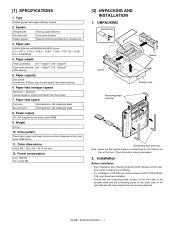
... the exit tray is installed to remove the actuator. Paper input section cover Exit actuator AR-RB1 UNPACKING AND INSTALLATION 2 - 2 Turn off the main switch of the main unit. 1) Turn the main switch located on the left side of the main unit to pull out the left side of AR-D17/D18: 1) Pull the lock release lever on the left cover until it . Transport guide holder: 2 pcs. 1. Paper output section covers In the...
... the exit tray is installed to remove the actuator. Paper input section cover Exit actuator AR-RB1 UNPACKING AND INSTALLATION 2 - 2 Turn off the main switch of the main unit. 1) Turn the main switch located on the left side of the main unit to pull out the left side of AR-D17/D18: 1) Pull the lock release lever on the left cover until it . Transport guide holder: 2 pcs. 1. Paper output section covers In the...
Service Manual
Page 4
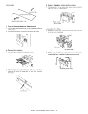
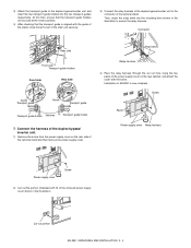
... duplex bypass/inverter unit and reattach the exit tray that there is no clearance between the main unit and the duplex bypass. Actuator 6. Transport guide Transport surface AR-RB1 UNPACKING AND INSTALLATION 2 - 3 Attach the transport guide. 1) Pull the lock release lever to the main unit. At this time, take care not to the main unit. 1) Close the left cover. Lock release lever 5. At this time, check...
... duplex bypass/inverter unit and reattach the exit tray that there is no clearance between the main unit and the duplex bypass. Actuator 6. Transport guide Transport surface AR-RB1 UNPACKING AND INSTALLATION 2 - 3 Attach the transport guide. 1) Pull the lock release lever to the main unit. At this time, take care not to the main unit. 1) Close the left cover. Lock release lever 5. At this time, check...
Service Manual
Page 5
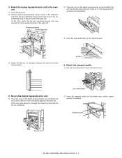
... the removed power supply cover shown in the illustration to the connector of the optional stand. Connector Rear side Snap band Front side Transport guide holders Front side Rear side Notch Transport guide Notch Transport guide Transport guide holder Notches Transport guide holder 7. Installation of AR-RB1 is aligned with the guide of the stand, close the left cover of the main unit securely. 3) Connect the relay harness of the duplex...
... the removed power supply cover shown in the illustration to the connector of the optional stand. Connector Rear side Snap band Front side Transport guide holders Front side Rear side Notch Transport guide Notch Transport guide Transport guide holder Notches Transport guide holder 7. Installation of AR-RB1 is aligned with the guide of the stand, close the left cover of the main unit securely. 3) Connect the relay harness of the duplex...
Service Manual
Page 6
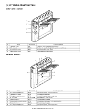
... capacity detection sensor BPFD 4 BY drive PWB BY drive PWB 5 Transport sensor 1 BPPD1 6 Reverse section detection sensor BPRD 7 Transport sensor 1 BPPD2 8 Door open/closed detector 2 BDD2 Function/operation Detects open /closed status of upper door Detects discharged paper Detects full capacity status in paper tray INVERTER drive and controller Detects transport of paper Detects presence of lower door AR-RB1 INTERIOR CONSTRUCTION 3 - 1 [3] INTERIOR CONSTRUCTION Motors...
... capacity detection sensor BPFD 4 BY drive PWB BY drive PWB 5 Transport sensor 1 BPPD1 6 Reverse section detection sensor BPRD 7 Transport sensor 1 BPPD2 8 Door open/closed detector 2 BDD2 Function/operation Detects open /closed status of upper door Detects discharged paper Detects full capacity status in paper tray INVERTER drive and controller Detects transport of paper Detects presence of lower door AR-RB1 INTERIOR CONSTRUCTION 3 - 1 [3] INTERIOR CONSTRUCTION Motors...
Service Manual
Page 7
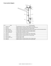
... direction. Applies a pressure to the paper feed roller to ADU. AR-RB1 INTERIOR CONSTRUCTION 3 - 2 Cross-section diagram 12 14 3 4 5 No. Transports paper to transport paper. Applies a pressure to the lower transport roller to ADU. Reverses paper and transports it to transport paper. Transports paper to transport and discharge paper. Applies a pressure to the delivery roller to ADU. Name 1 Delivery roller 2 Idle roller 3 Idle roller 4 Paper feed roller 5 Upper reverse roller 6 Upper transport roller...
... direction. Applies a pressure to the paper feed roller to ADU. AR-RB1 INTERIOR CONSTRUCTION 3 - 2 Cross-section diagram 12 14 3 4 5 No. Transports paper to transport paper. Applies a pressure to the lower transport roller to ADU. Reverses paper and transports it to transport paper. Transports paper to transport and discharge paper. Applies a pressure to the delivery roller to ADU. Name 1 Delivery roller 2 Idle roller 3 Idle roller 4 Paper feed roller 5 Upper reverse roller 6 Upper transport roller...
Service Manual
Page 8
... reverse tray delivery operation, the paper-in reverse to transport paper to ADU. AR-RB1 DESCRIPTION OF OPERATION 4 - 1 Afterward, the upper reverse motor stops, and the paper transport stops. Next, the upper reverse motor rotates in motor and the upper reverse motor operates, the paper is fed, and BPPD1 is transported to the direction of paper exit tray. After BPPD2 detects the passing paper, it turns off...
... reverse tray delivery operation, the paper-in reverse to transport paper to ADU. AR-RB1 DESCRIPTION OF OPERATION 4 - 1 Afterward, the upper reverse motor stops, and the paper transport stops. Next, the upper reverse motor rotates in motor and the upper reverse motor operates, the paper is fed, and BPPD1 is transported to the direction of paper exit tray. After BPPD2 detects the passing paper, it turns off...
Service Manual
Page 9
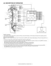
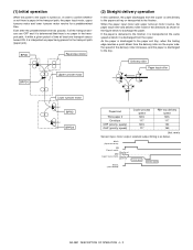
... of time at which it is sent directly to the paper exit tray or transported to the finisher. (1) Initial operation When the power to the copier is turned on the copier side, the speed of paper-out) Process speed BGSOL (Gate solenoid) Delivery speed AR-RB1 DESCRIPTION OF OPERATION 4 - 2 BPOD Paper input motor BPPD1 Upper turnover motor (2) Straight delivery operation In this operation, the paper discharged...
... of time at which it is sent directly to the paper exit tray or transported to the finisher. (1) Initial operation When the power to the copier is turned on the copier side, the speed of paper-out) Process speed BGSOL (Gate solenoid) Delivery speed AR-RB1 DESCRIPTION OF OPERATION 4 - 2 BPOD Paper input motor BPPD1 Upper turnover motor (2) Straight delivery operation In this operation, the paper discharged...
Service Manual
Page 10
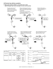
.../A5 All size RB1 transport speed (low speed) 450 430 400 320 195 Unit: mm/s Sensor input, motor output, solenoid output timing is as below. POD (Paper exit sensor) BPPD1 (Transport sensor 1) BPOD (Paper-out sensor) BIM (Paper-in motor) Process speed BRM (Direction of paper-in) (Upper reverse motor) (Direction of the paper reaches a point 50mm before delivery roller Transport speed (low speed) Motor stop ) The...
.../A5 All size RB1 transport speed (low speed) 450 430 400 320 195 Unit: mm/s Sensor input, motor output, solenoid output timing is as below. POD (Paper exit sensor) BPPD1 (Transport sensor 1) BPOD (Paper-out sensor) BIM (Paper-in motor) Process speed BRM (Direction of paper-in) (Upper reverse motor) (Direction of the paper reaches a point 50mm before delivery roller Transport speed (low speed) Motor stop ) The...
Service Manual
Page 11
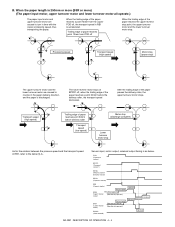
..., motor output, solenoid output timing is discharged. The lower reverse motor stops at BPPD1 off, when the trailing edge of paper-out) High speed Low speed High speed High speed High speed AR-RB1 DESCRIPTION OF OPERATION 4 - 4 POD (Paper exit sensor) BPPD1 (Transport sensor 1) BPRD (Reverse section detection sensor) BPOD (Paper-out sensor) BIM (Paper-in motor) Process speed BRM (Direction of paper-in...
..., motor output, solenoid output timing is discharged. The lower reverse motor stops at BPPD1 off, when the trailing edge of paper-out) High speed Low speed High speed High speed High speed AR-RB1 DESCRIPTION OF OPERATION 4 - 4 POD (Paper exit sensor) BPPD1 (Transport sensor 1) BPRD (Reverse section detection sensor) BPOD (Paper-out sensor) BIM (Paper-in motor) Process speed BRM (Direction of paper-in...
Service Manual
Page 12
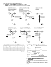
... motor) Process speed BRM (Direction of paper-in RB1 is caused to turn in time with the copier processing speed, thus transporting the paper. Just before the leading edge of the paper reaches the first roller of the paper passes the delivery roller, the upper turnover motor stops. AR-RB1 DESCRIPTION OF OPERATION 4 - 5 When paper length is 249mm or less (letter size or less) (Both the...
... motor) Process speed BRM (Direction of paper-in RB1 is caused to turn in time with the copier processing speed, thus transporting the paper. Just before the leading edge of the paper reaches the first roller of the paper passes the delivery roller, the upper turnover motor stops. AR-RB1 DESCRIPTION OF OPERATION 4 - 5 When paper length is 249mm or less (letter size or less) (Both the...
Service Manual
Page 13
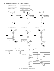
... (high) 195 550 550 Unit: mm/s Sensor input, motor output, solenoid output timing is caused to turn in the direction of the paper reaches the lower reverse stop point, the motor stops. When the trailing edge of paper-out) BGSOL (Gate solenoid) High speed High speed High speed AR-RB1 DESCRIPTION OF OPERATION 4 - 6 (5) ADU delivery operation (AR-D19 the installed) The paper input motor and upper turnover...
... (high) 195 550 550 Unit: mm/s Sensor input, motor output, solenoid output timing is caused to turn in the direction of the paper reaches the lower reverse stop point, the motor stops. When the trailing edge of paper-out) BGSOL (Gate solenoid) High speed High speed High speed AR-RB1 DESCRIPTION OF OPERATION 4 - 6 (5) ADU delivery operation (AR-D19 the installed) The paper input motor and upper turnover...
Service Manual
Page 14
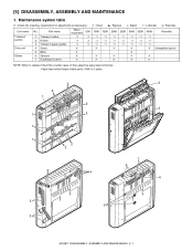
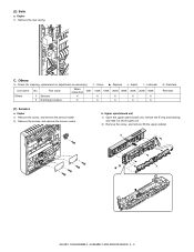
...; 7 Discharge brushes ✕ ✕ ✕ ✕ ✕ ✕ ✕ ✕ ✕ NOTE: When to replace: Check the counter value on the respective paper feed entrances. [5] DISASSEMBLY, ASSEMBLY AND MAINTENANCE 1. Paper feed rollers/torque limiter parts: 100K or 2 years. 2 2 1 2 1 2 1 1 2 2 4 4 3 3 7 6 6 5 6 5 AR-RB1 DISASSEMBLY, ASSEMBLY AND MAINTENANCE 5 - 1 Maintenance system table ✕ : Check (for cleaning, replacement or adjustment as necessary) ❍ : Clean v : Replace ∆ : Adjust ✩ : Lubricate ❏ : Relocate...
...; 7 Discharge brushes ✕ ✕ ✕ ✕ ✕ ✕ ✕ ✕ ✕ NOTE: When to replace: Check the counter value on the respective paper feed entrances. [5] DISASSEMBLY, ASSEMBLY AND MAINTENANCE 1. Paper feed rollers/torque limiter parts: 100K or 2 years. 2 2 1 2 1 2 1 1 2 2 4 4 3 3 7 6 6 5 6 5 AR-RB1 DISASSEMBLY, ASSEMBLY AND MAINTENANCE 5 - 1 Maintenance system table ✕ : Check (for cleaning, replacement or adjustment as necessary) ❍ : Clean v : Replace ∆ : Adjust ✩ : Lubricate ❏ : Relocate...
Service Manual
Page 15
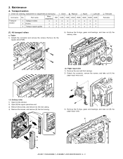
...; : Check (for cleaning, replacement or adjustment as necessary) ❍ : Clean v : Replace ∆ : Adjust ✩ : Lubricate Unit name Transport section No. A 5) Remove the E-rings, gears and bearings, and take out (B) the paper input roller. B AR-RB1 DISASSEMBLY, ASSEMBLY AND MAINTENANCE 5 - 2 B AD C 3) Remove the E-rings, gears and bearings, and take out (E) the delivery roller. Copier 1) Detach the connector and remove the screws. A Delivery roller 1) Open (A) the left door. 2) Open (B) the upper open/close unit. 3) Remove...
...; : Check (for cleaning, replacement or adjustment as necessary) ❍ : Clean v : Replace ∆ : Adjust ✩ : Lubricate Unit name Transport section No. A 5) Remove the E-rings, gears and bearings, and take out (B) the paper input roller. B AR-RB1 DISASSEMBLY, ASSEMBLY AND MAINTENANCE 5 - 2 B AD C 3) Remove the E-rings, gears and bearings, and take out (E) the delivery roller. Copier 1) Detach the connector and remove the screws. A Delivery roller 1) Open (A) the left door. 2) Open (B) the upper open/close unit. 3) Remove...
Service Manual
Page 17
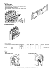
... 1) Remove the rear casing. 2) Remove the front gears. Drive section ✕ : Check (for cleaning, replacement or adjustment as necessary) ❍ : Clean v : Replace ∆ : Adjust ✩ : Lubricate ❏ : Relocate Unit name Drive unit No. Paper delivery cabinet 1) Remove the delivery roller. 2) Remove (A) the screw, remove (B) the ADU open/closed sensor mounting plate, and detach the connector. 3) Remove the screws, and take out (C) the paper delivery cabinet unit. (3) Transport paper guides C B A B. AR-RB1 DISASSEMBLY, ASSEMBLY AND MAINTENANCE 5 - 4 Part name...
... 1) Remove the rear casing. 2) Remove the front gears. Drive section ✕ : Check (for cleaning, replacement or adjustment as necessary) ❍ : Clean v : Replace ∆ : Adjust ✩ : Lubricate ❏ : Relocate Unit name Drive unit No. Paper delivery cabinet 1) Remove the delivery roller. 2) Remove (A) the screw, remove (B) the ADU open/closed sensor mounting plate, and detach the connector. 3) Remove the screws, and take out (C) the paper delivery cabinet unit. (3) Transport paper guides C B A B. AR-RB1 DISASSEMBLY, ASSEMBLY AND MAINTENANCE 5 - 4 Part name...
Service Manual
Page 18
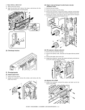
... 1) Remove the screw, and remove the sensor holder. 2) Remove the screws, and remove the sensor covers. b. (2) Belts a. C. Others ✕ : Check (for cleaning, replacement or adjustment as necessary) ❍ : Clean v : Replace ∆ : Adjust ✩ : Lubricate Unit name Others No. B A AR-RB1 DISASSEMBLY, ASSEMBLY AND MAINTENANCE 5 - 5 Upper open/closed unit 1) Open the upper open/closed unit, remove the E-ring and bearing, and take out (A) the gate unit. 2) Remove the screw, and remove (B) the upper cabinet. Copier 1) Remove the...
... 1) Remove the screw, and remove the sensor holder. 2) Remove the screws, and remove the sensor covers. b. (2) Belts a. C. Others ✕ : Check (for cleaning, replacement or adjustment as necessary) ❍ : Clean v : Replace ∆ : Adjust ✩ : Lubricate Unit name Others No. B A AR-RB1 DISASSEMBLY, ASSEMBLY AND MAINTENANCE 5 - 5 Upper open/closed unit 1) Open the upper open/closed unit, remove the E-ring and bearing, and take out (A) the gate unit. 2) Remove the screw, and remove (B) the upper cabinet. Copier 1) Remove the...
Service Manual
Page 19
... remove (A) the paper input motor. Paper delivery cabinet unit 1) Remove the rear casing. 2) Open the left door unit, remove the screw, and remove (A) the ADU open/closed sensor mounting plate. (2) Upper reverse transport motor/Lower reverse transport motor 1) Remove the rear casing. 2) Detach the harness from the clamp. 3) Remove the connector, remove the screws, and take out (A) the bypass drive PWB. A AR-RB1 DISASSEMBLY, ASSEMBLY AND MAINTENANCE...
... remove (A) the paper input motor. Paper delivery cabinet unit 1) Remove the rear casing. 2) Open the left door unit, remove the screw, and remove (A) the ADU open/closed sensor mounting plate. (2) Upper reverse transport motor/Lower reverse transport motor 1) Remove the rear casing. 2) Detach the harness from the clamp. 3) Remove the connector, remove the screws, and take out (A) the bypass drive PWB. A AR-RB1 DISASSEMBLY, ASSEMBLY AND MAINTENANCE...
Service Manual
Page 25
q PARTS GUIDE DUPLEX BYPASS/INVERTER UNIT MODEL AR-RB1 CONTENTS 1 Exteriors & Left door unit) 2 Upper Open/Shut unit) 3 Delivery paper unit & Upper transport section) 4 Lower transport section & Frame section) 5 Reverse base section) 6 配線部 (Wiring section) 7 Packing material & Accessories) I 索引 (Index) SHARP CORPORATION
q PARTS GUIDE DUPLEX BYPASS/INVERTER UNIT MODEL AR-RB1 CONTENTS 1 Exteriors & Left door unit) 2 Upper Open/Shut unit) 3 Delivery paper unit & Upper transport section) 4 Lower transport section & Frame section) 5 Reverse base section) 6 配線部 (Wiring section) 7 Packing material & Accessories) I 索引 (Index) SHARP CORPORATION
Service Manual
Page 26
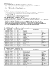
...;開閉 PG J 搬送 PG ロック PA F F B: Performance/function parts (sensors, clutches, and other than this Parts Guide, please refer to documents Service Manual(including Circuit Diagram)of this model. A B E D C DEFINITION The definition of each Rank is indispensable for the machine safety maintenance and operation, it must be replaced with "!" F F Other than the above (excluding sub components of PWB).
...;開閉 PG J 搬送 PG ロック PA F F B: Performance/function parts (sensors, clutches, and other than this Parts Guide, please refer to documents Service Manual(including Circuit Diagram)of this model. A B E D C DEFINITION The definition of each Rank is indispensable for the machine safety maintenance and operation, it must be replaced with "!" F F Other than the above (excluding sub components of PWB).


