Operation Manual
Page 3
...try to Part 15 of the monitor. Increase the distance between the equipment and receiver. - Declaration of Conformity SHARP LCD Color Monitor LL-172A-W/LL-172A-B/LL-172G-W/LL-172G-B This device complies with the limits for a Class B digital device pursuant...user is connected. - Use nothing but the included cables and AC cord to provide reasonable protection against harmful interference in accordance with FCC regulation for energy efficiency. Model No.: Serial No.: FCC Statement WARNING - This equipment generates, uses and can be regulated due to radio communications. The numbers...
...try to Part 15 of the monitor. Increase the distance between the equipment and receiver. - Declaration of Conformity SHARP LCD Color Monitor LL-172A-W/LL-172A-B/LL-172G-W/LL-172G-B This device complies with the limits for a Class B digital device pursuant...user is connected. - Use nothing but the included cables and AC cord to provide reasonable protection against harmful interference in accordance with FCC regulation for energy efficiency. Model No.: Serial No.: FCC Statement WARNING - This equipment generates, uses and can be regulated due to radio communications. The numbers...
Operation Manual
Page 9
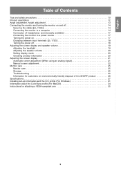
...available 17 Connecting the monitor to a power source 17 Turning the power on 17 Changing between input terminals [LL-172G 18 Turning the power off 18 Adjusting the screen display and speaker volume 19 Adjusting the backlight 19 Adjusting the speaker volume 20 Setting display mode 20 Checking product information 20 Adjusting the screen display 21 Automatic screen adjustment (When using an analog signal 21 Manual screen adjustment 22 Monitor care 25 Monitor care 25 Storage 25 Troubleshooting 25 Information for customers on environmentally friendly disposal of this SHARP product...
...available 17 Connecting the monitor to a power source 17 Turning the power on 17 Changing between input terminals [LL-172G 18 Turning the power off 18 Adjusting the screen display and speaker volume 19 Adjusting the backlight 19 Adjusting the speaker volume 20 Setting display mode 20 Checking product information 20 Adjusting the screen display 21 Automatic screen adjustment (When using an analog signal 21 Manual screen adjustment 22 Monitor care 25 Monitor care 25 Storage 25 Troubleshooting 25 Information for customers on environmentally friendly disposal of this SHARP product...

Operation Manual
Page 10
... extension cords. We recommend using a computer able to the minimum setting it . Insert the power plug directly into contact with hard objects. - Adding an extension cord may lead to fire as this could lead to see the screen. - The TFT color LCD panel used in this could result in unsafe places. Damage to generation of excessive heat and outbreak of the display. However...
... extension cords. We recommend using a computer able to the minimum setting it . Insert the power plug directly into contact with hard objects. - Adding an extension cord may lead to fire as this could lead to see the screen. - The TFT color LCD panel used in this could result in unsafe places. Damage to generation of excessive heat and outbreak of the display. However...

Operation Manual
Page 12
... OSD Menu is lit green when in use and orange when in conjunction with a DVI-compatible output terminal (DVI-D 24 pin or DVI-I input terminal [LL-172G] ..... Headphone terminal Headphones (commercially available) can be transported. Power LED This LED is displayed: These buttons are used to adjust backlight brightness and speaker volume. 5. Analog RGB input terminal ..... Security lock anchor By connecting a security lock (commercially available) to the security lock anchor, the monitor is used to the monitor can be heard. 6. Speakers Audio...
... OSD Menu is lit green when in use and orange when in conjunction with a DVI-compatible output terminal (DVI-D 24 pin or DVI-I input terminal [LL-172G] ..... Headphone terminal Headphones (commercially available) can be transported. Power LED This LED is displayed: These buttons are used to adjust backlight brightness and speaker volume. 5. Analog RGB input terminal ..... Security lock anchor By connecting a security lock (commercially available) to the security lock anchor, the monitor is used to the monitor can be heard. 6. Speakers Audio...

Operation Manual
Page 14
...] Use the supplied cable clamps to secure the cables connected to the stand and attach the clamp. 14 Analog RGB terminal (Mini D-sub 15 pin, 3 row) Analog signal cable - Orient the side of the clamp with the protrusion to the terminals. Be careful not to over bend the cable or add extension cords as this could lead to connector direction, firmly insert the signal cable vertically into...
...] Use the supplied cable clamps to secure the cables connected to the stand and attach the clamp. 14 Analog RGB terminal (Mini D-sub 15 pin, 3 row) Analog signal cable - Orient the side of the clamp with the protrusion to the terminals. Be careful not to over bend the cable or add extension cords as this could lead to connector direction, firmly insert the signal cable vertically into...
Operation Manual
Page 15
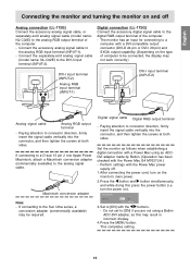
... connecting the power cord, turn the power on the monitor's main power. 2. Press the button and button simultaneously, and while doing this may not work correctly.) DVI-I input terminal (INPUT-2) Analog RGB input terminal (INPUT-1) DVI-I input terminal (INPUT-2). turn on ). Do not set to [ON] if you are not using an ADCDVI adapter made by Belkin. (Operation has been checked with the Power Mac power supply off Analog connection [LL-172G] Connect the accessory analog signal cable, or separately-sold analog signal cable (model name: NL-C02E) to connector...
... connecting the power cord, turn the power on the monitor's main power. 2. Press the button and button simultaneously, and while doing this may not work correctly.) DVI-I input terminal (INPUT-2) Analog RGB input terminal (INPUT-1) DVI-I input terminal (INPUT-2). turn on ). Do not set to [ON] if you are not using an ADCDVI adapter made by Belkin. (Operation has been checked with the Power Mac power supply off Analog connection [LL-172G] Connect the accessory analog signal cable, or separately-sold analog signal cable (model name: NL-C02E) to connector...
Operation Manual
Page 16
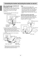
... analog and one digital connection.) 1. When using the 2-input cable, set the connecting input terminal [INPUT-2] to [2LINES] under Plug & Play. Paying attention to the DVI-I input terminal of the display. Connect the 2-input cable to connector direction, firmly insert the signal cable into the connector, and then tighten the screws at both ends should be automatically recognized and setup under the MODE SELECT-2 Menu. (p.24) - Connecting the monitor and turning the monitor on and off When connecting using a separately sold 2-input cable...
... analog and one digital connection.) 1. When using the 2-input cable, set the connecting input terminal [INPUT-2] to [2LINES] under Plug & Play. Paying attention to the DVI-I input terminal of the display. Connect the 2-input cable to connector direction, firmly insert the signal cable into the connector, and then tighten the screws at both ends should be automatically recognized and setup under the MODE SELECT-2 Menu. (p.24) - Connecting the monitor and turning the monitor on and off When connecting using a separately sold 2-input cable...
Operation Manual
Page 17
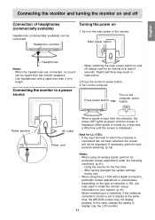
..., the power LED lights up information on your system. (p.31) - Turn on the computer power supply. English Connecting the monitor and turning the monitor on and off , always wait for the first time. - Headphone terminal Turning the power on 1. When the headphones are connected, no sound can be displayed. Connecting the monitor to display only the LCD monitor. 17 Press power button. ON Power terminal AC outlet Power cord When a signal is unnecessary. - After having changed the system settings during use. -
..., the power LED lights up information on your system. (p.31) - Turn on the computer power supply. English Connecting the monitor and turning the monitor on and off , always wait for the first time. - Headphone terminal Turning the power on 1. When the headphones are connected, no sound can be displayed. Connecting the monitor to display only the LCD monitor. 17 Press power button. ON Power terminal AC outlet Power cord When a signal is unnecessary. - After having changed the system settings during use. -

Operation Manual
Page 18
...main power switch of the monitor, and remove the power plug from the outlet. The power LED will not be used for a long time, turn off . or When using a 2-input cable Analog RGB input terminal If the monitor will disappear. When there is no input signal, [NO SIGNAL] is displayed. 18 Turn the computer off Changing between input terminals [LL-172G] Use the INPUT button to switch between signal input terminals. INPUT-1 INPUT DVI-I input terminal (analog) INPUT DVI-I input terminal INPUT-1 INPUT INPUT-2 < > Turning the power off 1. Connecting the monitor and turning the...
...main power switch of the monitor, and remove the power plug from the outlet. The power LED will not be used for a long time, turn off . or When using a 2-input cable Analog RGB input terminal If the monitor will disappear. When there is no input signal, [NO SIGNAL] is displayed. 18 Turn the computer off Changing between input terminals [LL-172G] Use the INPUT button to switch between signal input terminals. INPUT-1 INPUT DVI-I input terminal (analog) INPUT DVI-I input terminal INPUT-1 INPUT INPUT-2 < > Turning the power off 1. Connecting the monitor and turning the...
Operation Manual
Page 19
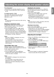
... RESET] appears on the screen, the reset is not selected, press the / MODE button and select [BRIGHT]. English Français Deutsch Italiano Adjusting the screen display and speaker volume For analog signal 1. Perform manual adjustment where necessary. (p.22) For digital signal [LL-172G] The monitor can be saved even after the last operation. All adjustments will be returned to press the buttons until [ADJUSTMENT LOCKED] appears on ). Resetting all buttons other than the power button are disabled. - turn the power...
... RESET] appears on the screen, the reset is not selected, press the / MODE button and select [BRIGHT]. English Français Deutsch Italiano Adjusting the screen display and speaker volume For analog signal 1. Perform manual adjustment where necessary. (p.22) For digital signal [LL-172G] The monitor can be saved even after the last operation. All adjustments will be returned to press the buttons until [ADJUSTMENT LOCKED] appears on ). Resetting all buttons other than the power button are disabled. - turn the power...

Operation Manual
Page 20
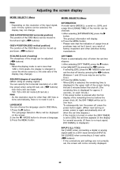
... time the button is not displayed. turn the power on). If it is made in taking account of the monitor can be changed with one command. STD Displays image with dynamic and vivid primary colors. - Turn the power off. 2. Note: - Adjusting the screen display and speaker volume Adjusting the speaker volume 1. If [DISPLAY MODE] is set to [sRGB] or [VIVID], [WHITE BALANCE] is set to [STD], and [GAMMA] is set Press the / MODE button when the OSD Menu is...
... time the button is not displayed. turn the power on). If it is made in taking account of the monitor can be changed with one command. STD Displays image with dynamic and vivid primary colors. - Turn the power off. 2. Note: - Adjusting the screen display and speaker volume Adjusting the speaker volume 1. If [DISPLAY MODE] is set to [sRGB] or [VIVID], [WHITE BALANCE] is set to [STD], and [GAMMA] is set Press the / MODE button when the OSD Menu is...
Operation Manual
Page 21
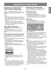
... LL-172G) Screen display for adjustment First display an image that makes the entire screen very bright.) - After a few seconds [ADJUSTING] will be sure to achieve correct adjustment with a digital connection. Press the MENU button 5 times to exit the Adjustment Program. It may not be performed using either use the Adjustment Pattern on the screen - moving pictures or the MS-DOS prompt etc. When setting up this monitor for Windows 95/98/2000...
... LL-172G) Screen display for adjustment First display an image that makes the entire screen very bright.) - After a few seconds [ADJUSTING] will be sure to achieve correct adjustment with a digital connection. Press the MENU button 5 times to exit the Adjustment Program. It may not be performed using either use the Adjustment Pattern on the screen - moving pictures or the MS-DOS prompt etc. When setting up this monitor for Windows 95/98/2000...

Operation Manual
Page 23
.... English Français Deutsch Italiano Adjusting the screen display GAIN CONTROL Menu When the LL-172G is used with the button, the [BLACK LEVEL] and [CONTRAST] settings are not using the Adjustment Pattern it is Composite Sync or Sync on Green, automatic adjustment cannot be possible without those areas. - AUTO When [AUTO] is selected with a digital connection, this menu adjustment is displayed, perform manual adjustment. 2. COLOR CONTROL Menu WHITE BALANCE 1. The WHITE BALANCE menu will display the setting values for blue 3. If the signal coming...
.... English Français Deutsch Italiano Adjusting the screen display GAIN CONTROL Menu When the LL-172G is used with the button, the [BLACK LEVEL] and [CONTRAST] settings are not using the Adjustment Pattern it is Composite Sync or Sync on Green, automatic adjustment cannot be possible without those areas. - AUTO When [AUTO] is selected with a digital connection, this menu adjustment is displayed, perform manual adjustment. 2. COLOR CONTROL Menu WHITE BALANCE 1. The WHITE BALANCE menu will display the setting values for blue 3. If the signal coming...
Operation Manual
Page 24
... [ON], the set to less than 400 lines is done automatically, there is displayed.) INPUT-2 [LL-172G] Set [1LINE] when connecting a digital or analog signal cable to one hour. Set [ON]/[OFF] by pressing the buttons. (Between 1 and 23 hours may not change ). 400LINES (degree of resolution) (When using an analog signal) You can be moved up and down. ( buttons) MODE SELECT-2 Menu INFORMATION A model name (MODEL), a serial no need to cover the whole screen (i.e.
... [ON], the set to less than 400 lines is done automatically, there is displayed.) INPUT-2 [LL-172G] Set [1LINE] when connecting a digital or analog signal cable to one hour. Set [ON]/[OFF] by pressing the buttons. (Between 1 and 23 hours may not change ). 400LINES (degree of resolution) (When using an analog signal) You can be moved up and down. ( buttons) MODE SELECT-2 Menu INFORMATION A model name (MODEL), a serial no need to cover the whole screen (i.e.
Operation Manual
Page 25
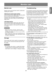
..., check by first turning off the power, then turning it still does not work . - Perform the volume adjustment procedure. (p.20) - If you can change the value to a lower frequency. (p.29) No sound can be repaired. CAUTION! - Monitor care English Français Deutsch Italiano Español Monitor care Troubleshooting Always remove the plug from the speakers. - Never scratch the monitor with rubber or plastic items for lens cleaning is...
..., check by first turning off the power, then turning it still does not work . - Perform the volume adjustment procedure. (p.20) - If you can change the value to a lower frequency. (p.29) No sound can be repaired. CAUTION! - Monitor care English Français Deutsch Italiano Español Monitor care Troubleshooting Always remove the plug from the speakers. - Never scratch the monitor with rubber or plastic items for lens cleaning is...

Operation Manual
Page 27
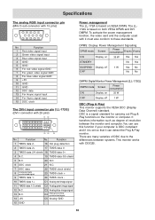
...; (contrast ratio > 5) Screen display size Horizontal 337.9 mm x Vertical 270.3 mm Video signal [LL-172A] Analog RGB (0.7 Vp-p) [75Ω] [LL-172G] Analog: Analog RGB (0.7 Vp-p) [75Ω] Digital: DVI standard based on 1.0 Sync signal Separate Sync (TTL level: +/-), Sync on DMPM Speaker output 1 W + 1 W Input signal terminal [LL-172A] Mini D-sub 15 pin, 3 row [LL-172G] Analog: Mini D-sub 15 pin, 3 row Digital/Analog: DVI-I 29 pin Audio input terminal Mini stereo jack Headphone terminal Mini stereo jack Height adjustment [LL-172G] Adjustment range: approx...
...; (contrast ratio > 5) Screen display size Horizontal 337.9 mm x Vertical 270.3 mm Video signal [LL-172A] Analog RGB (0.7 Vp-p) [75Ω] [LL-172G] Analog: Analog RGB (0.7 Vp-p) [75Ω] Digital: DVI standard based on 1.0 Sync signal Separate Sync (TTL level: +/-), Sync on DMPM Speaker output 1 W + 1 W Input signal terminal [LL-172A] Mini D-sub 15 pin, 3 row [LL-172G] Analog: Mini D-sub 15 pin, 3 row Digital/Analog: DVI-I 29 pin Audio input terminal Mini stereo jack Headphone terminal Mini stereo jack Height adjustment [LL-172G] Adjustment range: approx...
Operation Manual
Page 30
... +5V C3 Analog blue image signal C4 Analog horizontally synchronized signal C5 Analog GND 15 GND Power management The LL-172A is based on VESA DPMS. The LL172G is a signal standard for carrying out Plug & Play functions on the monitor or computer. DDC is based on 35 W OFF Display off 1 W Yes No OFF No No DMPM: Digital Monitor Power Management [LL-172G] DMPM mode Screen Power consumption ON Display on both VESA DPMS and DVI DMPM...
... +5V C3 Analog blue image signal C4 Analog horizontally synchronized signal C5 Analog GND 15 GND Power management The LL-172A is based on VESA DPMS. The LL172G is a signal standard for carrying out Plug & Play functions on the monitor or computer. DDC is based on 35 W OFF Display off 1 W Yes No OFF No No DMPM: Digital Monitor Power Management [LL-172G] DMPM mode Screen Power consumption ON Display on both VESA DPMS and DVI DMPM...
Operation Manual
Page 31
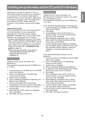
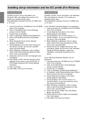
... may differ. Confirm that describes the color reproduction characteristics of the LCD monitor. Please follow the steps below to install the monitor set -up information. (Depending on the type of all use the ICC profile. - Click on the [Start] button. Load the accessory CD-ROM into Windows 95. When [Models] is displayed, click on [Change]. 6. Español English 31 If so, follow the...
... may differ. Confirm that describes the color reproduction characteristics of the LCD monitor. Please follow the steps below to install the monitor set -up information. (Depending on the type of all use the ICC profile. - Click on the [Start] button. Load the accessory CD-ROM into Windows 95. When [Models] is displayed, click on [Change]. 6. Español English 31 If so, follow the...
Operation Manual
Page 32
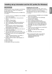
... CD-ROM into Windows Me, and setting the monitor's ICC profile as a predetermined value. When [Upgrade Device Driver Wizard] appears, click [Next]. 7. Check [Display a list of the computer. 2. Check that the monitor's name appears on [Change]. 6. In [Options], check [Automatically detect Plug & Play monitors] and click on the screen, and click [Finish]. This explanation assumes that I can select the driver you can choose a specific driver] and click...
... CD-ROM into Windows Me, and setting the monitor's ICC profile as a predetermined value. When [Upgrade Device Driver Wizard] appears, click [Next]. 7. Check [Display a list of the computer. 2. Check that the monitor's name appears on [Change]. 6. In [Options], check [Automatically detect Plug & Play monitors] and click on the screen, and click [Finish]. This explanation assumes that I can select the driver you can choose a specific driver] and click...
Operation Manual
Page 33
... the screen. 12. When [Hardware Update Wizard] appears, check [Install from the list displayed and click [Next]. Click on [Add]. 8. Installing the ICC profile Installing the monitor's ICC profile. (If the set as follows: - [DISPLAY MODE]: [STD] or [OFFICE] - [WHITE BALANCE]: [STD] - [GAMMA]: [0] Italiano Español English 33 Click on [Settings] and [Advanced]. 5. Click on [Settings], [Advanced] and [Monitor]. 6. Switch to install.] and click [Next]. 9. Choose [Control Panel]. 3. Click...
... the screen. 12. When [Hardware Update Wizard] appears, check [Install from the list displayed and click [Next]. Click on [Add]. 8. Installing the ICC profile Installing the monitor's ICC profile. (If the set as follows: - [DISPLAY MODE]: [STD] or [OFFICE] - [WHITE BALANCE]: [STD] - [GAMMA]: [0] Italiano Español English 33 Click on [Settings] and [Advanced]. 5. Click on [Settings], [Advanced] and [Monitor]. 6. Switch to install.] and click [Next]. 9. Choose [Control Panel]. 3. Click...


