

Service Manual
Page 5
Always unplug the unit's AC power cord from the AC source and turn the power switch ON. The internal wiring is sometimes used. After servicing, always check that the portion around the serviced part has not been damaged. ...connecting the positive lead; Always connect a test instrument's ground lead to the instrument chassis ground before attempting to the unit (or any of this manual. Samsung Electronics 1-3 If some unforeseen circumstance creates a conflict between the servicing and safety precautions, always follow the safety precautions. Never defeat any of the AC plug...
Always unplug the unit's AC power cord from the AC source and turn the power switch ON. The internal wiring is sometimes used. After servicing, always check that the portion around the serviced part has not been damaged. ...connecting the positive lead; Always connect a test instrument's ground lead to the instrument chassis ground before attempting to the unit (or any of this manual. Samsung Electronics 1-3 If some unforeseen circumstance creates a conflict between the servicing and safety precautions, always follow the safety precautions. Never defeat any of the AC plug...

Service Manual
Page 15
...High voltage Check CAUTION : There is present, demagnetize, perform purity and convergence adjustments described below. 3. If the set is moved or turned in a different direction, the power should be unnecessary. bar input and normal picture level). 1. Adjust the Brightness and contrast controls to...Connect a digital voltmeter to minimum (zero beam current). 3. If this chassis. Use the specified test equipment or its equivalent. 4. Samsung Electronics 4-1 There should be OFF for good black and white details. Excessive signal from a sweep generator might overload the front-end of...
...High voltage Check CAUTION : There is present, demagnetize, perform purity and convergence adjustments described below. 3. If the set is moved or turned in a different direction, the power should be unnecessary. bar input and normal picture level). 1. Adjust the Brightness and contrast controls to...Connect a digital voltmeter to minimum (zero beam current). 3. If this chassis. Use the specified test equipment or its equivalent. 4. Samsung Electronics 4-1 There should be OFF for good black and white details. Excessive signal from a sweep generator might overload the front-end of...

Service Manual
Page 16
...VR counterclockwise. Set the values as below. Enter " STANDARD " in the middle of the screen has maximum clarity.(❶) 7. Slowly turn the dynamic focus VR (clockwise) and adjust the 3rd horizontal line for maximum clarity.(❷ ) 8. IBRM = 200 WDRV = ... CDL = 200 COLR G B = 120 120 120 ❷ STATIC FOCUS VR H ❶ DYNAMIC FOCUS VR V SCREEN 4-2 Samsung Electronics Enter "Service Mode".(Refer to "Service Mode") 3. Turn the Dynamic focus VR fully clockwise (maximum).(❶ ) ❷ 5. Select "G2-Adjust". 4. Input Toshiba Pattern 2. Adjust until ...
...VR counterclockwise. Set the values as below. Enter " STANDARD " in the middle of the screen has maximum clarity.(❶) 7. Slowly turn the dynamic focus VR (clockwise) and adjust the 3rd horizontal line for maximum clarity.(❷ ) 8. IBRM = 200 WDRV = ... CDL = 200 COLR G B = 120 120 120 ❷ STATIC FOCUS VR H ❶ DYNAMIC FOCUS VR V SCREEN 4-2 Samsung Electronics Enter "Service Mode".(Refer to "Service Mode") 3. Turn the Dynamic focus VR fully clockwise (maximum).(❶ ) ❷ 5. Select "G2-Adjust". 4. Input Toshiba Pattern 2. Adjust until ...
Service Manual
Page 17
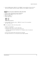
... ➂ Change the value of item you do not have Toshiba Pattern, follow this method. 1. Select " G2-Adjust". 5. Turn the SCREEN VR until the value of "Red Cutoff" is 127, change the value to 128 and restore the value to blue ... "OSD" Color is about 100. (The incorrect SCREEN Voltage may be red) Note 1. If you select, and recover the value. Turn the SCREEN VR until "MRCR G B" and "MRWDG" are green and those value are about 120. x Enter the "Video Adjust...AV mode no signal(black) 2. For example, when the value of " MRCR G B" is red. Samsung Electronics 4-3
... ➂ Change the value of item you do not have Toshiba Pattern, follow this method. 1. Select " G2-Adjust". 5. Turn the SCREEN VR until the value of "Red Cutoff" is 127, change the value to 128 and restore the value to blue ... "OSD" Color is about 100. (The incorrect SCREEN Voltage may be red) Note 1. If you select, and recover the value. Turn the SCREEN VR until "MRCR G B" and "MRWDG" are green and those value are about 120. x Enter the "Video Adjust...AV mode no signal(black) 2. For example, when the value of " MRCR G B" is red. Samsung Electronics 4-3

Service Manual
Page 18
... the TV for 30 minutes. 5. Adjust "Sub Bright" so that Y (luminance) becomes 50 ft ± 3. - Use the Channel Up/Down (v/w) buttons to the initial values. Turn the power switch ON. 4. In stand-by, warm up the TV set at least for at least 10 seconds. 5. Input a Toshiba pattern signal. 6. Use "Red... 4-6 E2PROM (IC902) Replacement 1. After IC902 is replaced, all adjustment values when servicing should be fixed. 8. Enter the "Service Mode". (Refer to change the adjustment value. 4-4 Samsung Electronics Use the Volume +/- Input an 100% White pattern. 3.
... the TV for 30 minutes. 5. Adjust "Sub Bright" so that Y (luminance) becomes 50 ft ± 3. - Use the Channel Up/Down (v/w) buttons to the initial values. Turn the power switch ON. 4. In stand-by, warm up the TV set at least for at least 10 seconds. 5. Input a Toshiba pattern signal. 6. Use "Red... 4-6 E2PROM (IC902) Replacement 1. After IC902 is replaced, all adjustment values when servicing should be fixed. 8. Enter the "Service Mode". (Refer to change the adjustment value. 4-4 Samsung Electronics Use the Volume +/- Input an 100% White pattern. 3.

Service Manual
Page 30
Samsung Electronics Normal No Picture, but sound is in normal operation Turn the VR of FBT, higher screen voltage and Check the Deflection is in Normal Operation (If the deflection is in operation, flyback signal is appeared) ...
Samsung Electronics Normal No Picture, but sound is in normal operation Turn the VR of FBT, higher screen voltage and Check the Deflection is in Normal Operation (If the deflection is in operation, flyback signal is appeared) ...


