
User Manual
Page 1
To receive a more complete service, please register your product at www.samsungsecurity.com SHR-7080/7082/7160/7162 SHR-8080/8082/8160/8162 8 Channel/16 Channel DVR User's Manual imagine the possibilities Thanks you for purchasing this Samsung product.
To receive a more complete service, please register your product at www.samsungsecurity.com SHR-7080/7082/7160/7162 SHR-8080/8082/8160/8162 8 Channel/16 Channel DVR User's Manual imagine the possibilities Thanks you for purchasing this Samsung product.
User Manual
Page 2
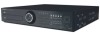
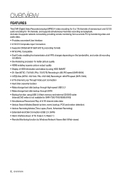
...using HDD SMART • D1 Size (NTSC: 704*480, PAL: 704*576) Recording in 480 IPS speed (SHR-8XXX) • CIF(S) Size (NTSC: 352*240, PAL: 352*288) Recording in 480 IPS speed (SHR-7XXX) • 8/16-channel Loop Through Video port connection • Hard Disk overwrite function • Mass .... overview FEATURES This DVR (Digital Video Recorder) employs MPEG-4 video encoding for 8 or 16 channels of camera input and G.723 audio encoding for SHR-7080/7160/8080/8160) • Simultaneous Record and Play of HDD information and status by Windows Network Viewer (Net-I/Web viewer) 2_ overview
...using HDD SMART • D1 Size (NTSC: 704*480, PAL: 704*576) Recording in 480 IPS speed (SHR-8XXX) • CIF(S) Size (NTSC: 352*240, PAL: 352*288) Recording in 480 IPS speed (SHR-7XXX) • 8/16-channel Loop Through Video port connection • Hard Disk overwrite function • Mass .... overview FEATURES This DVR (Digital Video Recorder) employs MPEG-4 video encoding for 8 or 16 channels of camera input and G.723 audio encoding for SHR-7080/7160/8080/8160) • Simultaneous Record and Play of HDD information and status by Windows Network Viewer (Net-I/Web viewer) 2_ overview

User Manual
Page 3
type plug. if the provided plug does not fit into the apparatus, the apparatus has been exposed to qualified service personnel. A grounding type plug has two blades and a third grounding prong. When a cart is used, use caution when moving the cart/apparatus combination to avoid injury from the apparatus. 11) Only use this apparatus during lightning storms or when unused for your outlet, consult an electrician for replacement of time. 14) Refer all servicing to rain or moisture, does not operate normally, or has been dropped. A polarized plug has two blades ...
type plug. if the provided plug does not fit into the apparatus, the apparatus has been exposed to qualified service personnel. A grounding type plug has two blades and a third grounding prong. When a cart is used, use caution when moving the cart/apparatus combination to avoid injury from the apparatus. 11) Only use this apparatus during lightning storms or when unused for your outlet, consult an electrician for replacement of time. 14) Refer all servicing to rain or moisture, does not operate normally, or has been dropped. A polarized plug has two blades ...
User Manual
Page 4
For information on its guaranteed temperature range is 0°C ~ 40°C (32°F ~ 104°F). special handling may cause an explosion. Warning ❖ Battery Exchanging a wrong battery in your product may apply, See www.dtsc.ca.gov/hazardouswaste/perchlorate." This product may not work at a temperature below the guaranteed one. overview BEFORE START This user's manual provides Information for a while and run right after a long period of storage at room temperature for using now. • Normal voltage: 3V • Normal capacity: 170mAh • ...
For information on its guaranteed temperature range is 0°C ~ 40°C (32°F ~ 104°F). special handling may cause an explosion. Warning ❖ Battery Exchanging a wrong battery in your product may apply, See www.dtsc.ca.gov/hazardouswaste/perchlorate." This product may not work at a temperature below the guaranteed one. overview BEFORE START This user's manual provides Information for a while and run right after a long period of storage at room temperature for using now. • Normal voltage: 3V • Normal capacity: 170mAh • ...
User Manual
Page 5
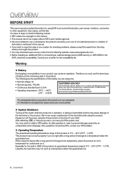
Package Contents Please unwrap the product, and place the product on a flat his own expense. This equipment generates, uses, and can radiate radio frequency energy and, if not installed and used in accordance with the limits for a Class A digital device, pursuant to correct the interference at place or in the place to radio communications. Operation of this equipment in a residential area is operated in which case the user will be installed. OVERVIEW Standards Approvals M This equipment has been tested and found to comply with the instruction manual...
Package Contents Please unwrap the product, and place the product on a flat his own expense. This equipment generates, uses, and can radiate radio frequency energy and, if not installed and used in accordance with the limits for a Class A digital device, pursuant to correct the interference at place or in the place to radio communications. Operation of this equipment in a residential area is operated in which case the user will be installed. OVERVIEW Standards Approvals M This equipment has been tested and found to comply with the instruction manual...
User Manual
Page 6
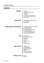
overview CONTENTS OVERVIEW 2 2 Features 3 Important Safety Instructions 4 Before Start 6 Contents 8 Part Names and Functions (Front) 10 Part Names and Functions (Rear) 12 Remote Control INSTALLATION 14 14 Checking the installation environment 15 Rack Installation 15 HDD Addition CONNECTING WITH OTHER DEVICE 19 19 Connecting the Video, Audio, and Monitor 19 Connecting the Network 20 Connecting the USB 20 Connecting External SATA HDD 21 Connecting POS Device 21 Connecting the Alarm Input/Output 22 Connecting the RS-485 Device LIVE 23 23 Getting Started 25 Live Screen Configuration 29 ...
overview CONTENTS OVERVIEW 2 2 Features 3 Important Safety Instructions 4 Before Start 6 Contents 8 Part Names and Functions (Front) 10 Part Names and Functions (Rear) 12 Remote Control INSTALLATION 14 14 Checking the installation environment 15 Rack Installation 15 HDD Addition CONNECTING WITH OTHER DEVICE 19 19 Connecting the Video, Audio, and Monitor 19 Connecting the Network 20 Connecting the USB 20 Connecting External SATA HDD 21 Connecting POS Device 21 Connecting the Alarm Input/Output 22 Connecting the RS-485 Device LIVE 23 23 Getting Started 25 Live Screen Configuration 29 ...
User Manual
Page 7
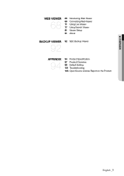
OVERVIEW WEB VIEWER 68 68 Introducing Web Viewer 69 Connecting Web Viewer 71 Using Live Viewer 77 Using Search Viewer 81 Viewer Setup 91 About BACKUP VIEWER 92 92 SEC Backup Viewer APPENDIX 94 94 Product Specification 97 Product Overview 98 Default Setting 101 Troubleshooting 103 Open Source License Report on the Product English _7
OVERVIEW WEB VIEWER 68 68 Introducing Web Viewer 69 Connecting Web Viewer 71 Using Live Viewer 77 Using Search Viewer 81 Viewer Setup 91 About BACKUP VIEWER 92 92 SEC Backup Viewer APPENDIX 94 94 Product Specification 97 Product Overview 98 Default Setting 101 Troubleshooting 103 Open Source License Report on the Product English _7
User Manual
Page 8
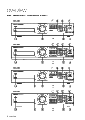
overview PART NAMES AND FUNCTIONS (FRONT) 7080/8080 123 4 10 7160/8160 8 7 6 5 123 4 10 7082/8082 8 7 6 5 123 4 10 7162/8162 9 8 7 6 5 123 4 10 8_ overview 9 8 7 6 5
overview PART NAMES AND FUNCTIONS (FRONT) 7080/8080 123 4 10 7160/8160 8 7 6 5 123 4 10 7082/8082 8 7 6 5 123 4 10 7162/8162 9 8 7 6 5 123 4 10 8_ overview 9 8 7 6 5

User Manual
Page 9
... the FREEZE function in the numeric input mode. SEARCH(PRESET) : Goes to the upper menu from the lower menu. Fast Rewind () : Used for SHR-7082/7162/8082/8162 only) Power LED : Displays the power ON/OFF status. Connects the USB devices. split screen, PIP, and auto sequence mode in order. (1 live...
... the FREEZE function in the numeric input mode. SEARCH(PRESET) : Goes to the upper menu from the lower menu. Fast Rewind () : Used for SHR-7082/7162/8082/8162 only) Power LED : Displays the power ON/OFF status. Connects the USB devices. split screen, PIP, and auto sequence mode in order. (1 live...

User Manual
Page 10
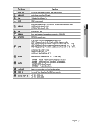
overview PART NAMES AND FUNCTIONS (REAR) 7080/7082 Rear 1 2 3 4 5 6 7 8 9 10 11 12 13 14 7160/7162 Rear 1 2 3 4 5 6 7 8 9 10 11 12 13 14 8080/8082 Rear 1 2 3 4 5 6 7 8 9 10 11 12 13 14 8160/8162 Rear 1 2 3 4 5 6 7 8 9 10 11 12 13 14 10_ overview
overview PART NAMES AND FUNCTIONS (REAR) 7080/7082 Rear 1 2 3 4 5 6 7 8 9 10 11 12 13 14 7160/7162 Rear 1 2 3 4 5 6 7 8 9 10 11 12 13 14 8080/8082 Rear 1 2 3 4 5 6 7 8 9 10 11 12 13 14 8160/8162 Rear 1 2 3 4 5 6 7 8 9 10 11 12 13 14 10_ overview
User Manual
Page 11
SHR-8162/8160 : SPOT 1,2,3,4 SHR-8082/8080 : SPOT 1,2 SHR-7162/7160/7082/7080 : SPOT 1 Used for 9 ~ 12 CH). ALARM IN 1~8(SHR-7080,7082,8080,8082): Alarm Input port. - Composite Video Signal Input Port (BNC type connector). AC 100 ~ 230V (PAL) AC 110 ~ 220V (NTSC) ...Output Port (BNC type connector). VGA Video Signal Output Port. HDMI connector port. Audio input signal port (RCA Jack) and port for 5 ~ 8 CH). SHR-716x/816x (Audio 5~16CH) SHR-808x/708x (Audio 5~8CH) USB connector port. ALARM IN 1~16(SHR-7160,7162,8160,8162): Alarm Input port. - ALARM RESET IN: Alarm Reset port. -
SHR-8162/8160 : SPOT 1,2,3,4 SHR-8082/8080 : SPOT 1,2 SHR-7162/7160/7082/7080 : SPOT 1 Used for 9 ~ 12 CH). ALARM IN 1~8(SHR-7080,7082,8080,8082): Alarm Input port. - Composite Video Signal Input Port (BNC type connector). AC 100 ~ 230V (PAL) AC 110 ~ 220V (NTSC) ...Output Port (BNC type connector). VGA Video Signal Output Port. HDMI connector port. Audio input signal port (RCA Jack) and port for 5 ~ 8 CH). SHR-716x/816x (Audio 5~16CH) SHR-808x/708x (Audio 5~8CH) USB connector port. ALARM IN 1~16(SHR-7160,7162,8160,8162): Alarm Input port. - ALARM RESET IN: Alarm Reset port. -
User Manual
Page 12
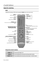
DVR Activates the DVR function. Select 2 digits from 0 ~ 9 while pressing the ID Key. REC LOCK Selects the recording lock function. Press the [+10] button first, then press any number between 1 to the previous/next frame. RETURN Returns to 6 within 3 seconds. Using the numeric buttons CHANNEL 1-9 CHANNEL 10 CHANNEL 11-16 Press each button between 1 to the previous screen. NUMBER [0~+10] Used as the numeric input keys, or displays a single channelĕ Skip Backward (by unit time), Slow Rewind, Slow Forward, Skip Forward (by pressing the [DVR] button on /off. ...
DVR Activates the DVR function. Select 2 digits from 0 ~ 9 while pressing the ID Key. REC LOCK Selects the recording lock function. Press the [+10] button first, then press any number between 1 to the previous/next frame. RETURN Returns to 6 within 3 seconds. Using the numeric buttons CHANNEL 1-9 CHANNEL 10 CHANNEL 11-16 Press each button between 1 to the previous screen. NUMBER [0~+10] Used as the numeric input keys, or displays a single channelĕ Skip Backward (by unit time), Slow Rewind, Slow Forward, Skip Forward (by pressing the [DVR] button on /off. ...
User Manual
Page 13
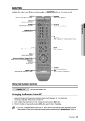
ID Sets the ID. Changing the Remote Control ID 1. When ID input is done, press the system [ID] button again to "Remote Devices". (Page 45) English _13 PIP Selects or deselects the PIP function. MONITOR Activates the monitor function. FREEZE Screen Freezeĕ UNDER SCAN Displays the video screen within a screenĕ MUTE Mutes the audio out. The factory default ID of your selection in order while the system [ID] button is 00. 2. Enter 2 digits of the remote control is pressed. Refer to check the setting. NUMBER [0~9] Changes the system ID. Select 2 digits from 0 ...
ID Sets the ID. Changing the Remote Control ID 1. When ID input is done, press the system [ID] button again to "Remote Devices". (Page 45) English _13 PIP Selects or deselects the PIP function. MONITOR Activates the monitor function. FREEZE Screen Freezeĕ UNDER SCAN Displays the video screen within a screenĕ MUTE Mutes the audio out. The factory default ID of your selection in order while the system [ID] button is 00. 2. Enter 2 digits of the remote control is pressed. Refer to check the setting. NUMBER [0~9] Changes the system ID. Select 2 digits from 0 ...
User Manual
Page 14
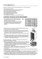
... circulation. 4. Please ensure the air is not achieved due to the following or similar rack-mount instructions are the recommendations when Samsung DVR is not sealed. 2. Please pay attention to uneven mechanical loading. The following recommendations before you use the product. •... should be stacked as in a rack should be such that the amount of power strips). 14_ installation CHECKING THE INSTALLATION ENVIRONMENT • Samsung Digital Video Recorder ("DVR" hereinafter) is installed at the inlet and the outlet for air circulation. (Please fit a filter...
... circulation. 4. Please ensure the air is not achieved due to the following or similar rack-mount instructions are the recommendations when Samsung DVR is not sealed. 2. Please pay attention to uneven mechanical loading. The following recommendations before you use the product. •... should be stacked as in a rack should be such that the amount of power strips). 14_ installation CHECKING THE INSTALLATION ENVIRONMENT • Samsung Digital Video Recorder ("DVR" hereinafter) is installed at the inlet and the outlet for air circulation. (Please fit a filter...
User Manual
Page 15
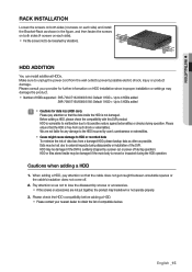
... or recorded data To minimize the risk of data loss from the wall outlet to obtain the list of HDDs supported : SHR-7082/7162/8082/8162: Default 1 HDD + Up to 4 HDDs added SHR-7080/7160/8080/8160: Default 1 HDD + Up to 5 HDDs added J Cautions for further information on each side). Fix...
... or recorded data To minimize the risk of data loss from the wall outlet to obtain the list of HDDs supported : SHR-7082/7162/8082/8162: Default 1 HDD + Up to 4 HDDs added SHR-7080/7160/8080/8160: Default 1 HDD + Up to 5 HDDs added J Cautions for further information on each side). Fix...
User Manual
Page 16
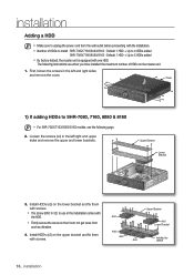
..., see the following instructions are when you have installed the maximum number of HDDs to install : SHR-7082/7162/8082/8162 : Default 1 HDD + Up to 4 HDDs added SHR-7080/7160/8080/8160 : Default 1 HDD + Up to 5 HDDs added By factory default, the master unit is equipped with one HDD. Upper Bracket Lower...
..., see the following instructions are when you have installed the maximum number of HDDs to install : SHR-7082/7162/8082/8162 : Default 1 HDD + Up to 4 HDDs added SHR-7080/7160/8080/8160 : Default 1 HDD + Up to 5 HDDs added By factory default, the master unit is equipped with one HDD. Upper Bracket Lower...

User Manual
Page 17
... Lower Bracket 6. Loosen the screws (x4) in the left/right and upper sides to remove the upper bracket and loosen the lower screws (x2) to SHR-7082, 7162, 8082 & 8162 2.
... Lower Bracket 6. Loosen the screws (x4) in the left/right and upper sides to remove the upper bracket and loosen the lower screws (x2) to SHR-7082, 7162, 8082 & 8162 2.
User Manual
Page 18
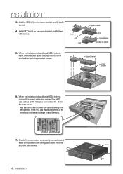
installation 3. When the installation of each connector. 7. Cover 18_ installation Just make arrangements of the connectors considering the length of additional HDDs is done, insert the lower and upper brackets into the DVR and fix them with screws. 4. Check if the connectors are properly connected and there is nothing to connectors ~ on the main board. Note that the number of a HDD data calbe is no problem with wiring, and close the cover and fix it with screws. Add Add Add Upper Bracket Add Lower Bracket Installed by default 5. When the installation of...
installation 3. When the installation of each connector. 7. Cover 18_ installation Just make arrangements of the connectors considering the length of additional HDDs is done, insert the lower and upper brackets into the DVR and fix them with screws. 4. Check if the connectors are properly connected and there is nothing to connectors ~ on the main board. Note that the number of a HDD data calbe is no problem with wiring, and close the cover and fix it with screws. Add Add Add Upper Bracket Add Lower Bracket Installed by default 5. When the installation of...
User Manual
Page 19
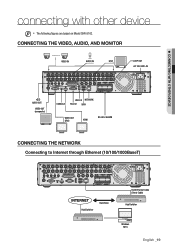
CONNECTING WITH OTHER DEVICE connecting with other device M The following figures are based on Model SHR-8162. CONNECTING THE VIDEO, AUDIO, AND MONITOR VIDEO IN AUDIO IN SPOT LOOP OUT AC 100-240V~IN AUDIO OUT VIDEO OUT (composite) CONSOLE USB 2.0 NETWORK RS-232 SATA VIDEO OUT (VGA) HDMI RS-485 / ALARM CONNECTING THE NETWORK Connecting to Internet through Ethernet (10/100/1000BaseT) Hub/Switcher Back Bone RJ45 Ethernet Cable (Direct Cable) Hub/Switcher Windows NET-i English _19
CONNECTING WITH OTHER DEVICE connecting with other device M The following figures are based on Model SHR-8162. CONNECTING THE VIDEO, AUDIO, AND MONITOR VIDEO IN AUDIO IN SPOT LOOP OUT AC 100-240V~IN AUDIO OUT VIDEO OUT (composite) CONSOLE USB 2.0 NETWORK RS-232 SATA VIDEO OUT (VGA) HDMI RS-485 / ALARM CONNECTING THE NETWORK Connecting to Internet through Ethernet (10/100/1000BaseT) Hub/Switcher Back Bone RJ45 Ethernet Cable (Direct Cable) Hub/Switcher Windows NET-i English _19
User Manual
Page 20
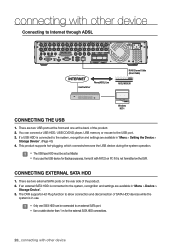
There are two USB ports at the front and one SATA HDD can connect a USB HDD, USB CD/DVD player, USB memory or mouse to an external SATA port. Use a cable shorter than 1 m for Backup purposes, format it with FAT32 on PC if it is not formatted on the rear side of the product. 2. J Only one at the back of the product. 2. You can be set as Master. If you use . The DVR supports Hot Plug function to Internet through ADSL Hub/Switcher Phone(ADSL) Line RJ45 Ethernet Cable (Direct Cable) ADSL MODEM Windows NET-i CONNECTING THE USB 1. There are ...
There are two USB ports at the front and one SATA HDD can connect a USB HDD, USB CD/DVD player, USB memory or mouse to an external SATA port. Use a cable shorter than 1 m for Backup purposes, format it with FAT32 on PC if it is not formatted on the rear side of the product. 2. J Only one at the back of the product. 2. You can be set as Master. If you use . The DVR supports Hot Plug function to Internet through ADSL Hub/Switcher Phone(ADSL) Line RJ45 Ethernet Cable (Direct Cable) ADSL MODEM Windows NET-i CONNECTING THE USB 1. There are ...