Service Manual
Page 2
MAY. 2004 Printed in Korea AA82-01672A Any unauthorized use of Samsung Electronics Co.,Ltd. ELECTRONICS This Service Manual is a property of Manual can be punished under applicable International and/or domestic law. © Samsung Electronics Co., Ltd.
MAY. 2004 Printed in Korea AA82-01672A Any unauthorized use of Samsung Electronics Co.,Ltd. ELECTRONICS This Service Manual is a property of Manual can be punished under applicable International and/or domestic law. © Samsung Electronics Co., Ltd.
Service Manual
Page 3
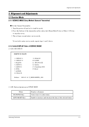
... the buttons of SERVICE MODE 2-1-2(A) OSD DISPLAY SERVICE MAIN 1. The set turns on . 3. VSP9437-1 2. VSP9437-2 3. Reset Release : 2003-07-12 T_NEW63MWW_1001 2-1-2(B) Button Operations in this order; ASI500-1 5. Alignment and Adjustments 2-1 Service Mode 2-1-1 SERVICE MODE Entry Method (General Transmitter) I For the General Transmitter 1. Info-Menu-Mute-Power or Mute-1-8-Power to turn the set to increase and decrease the data of the selected items Samsung Electronics 2-1 FLI2300 4. CheckSum 0000 14. Turn the power...
... the buttons of SERVICE MODE 2-1-2(A) OSD DISPLAY SERVICE MAIN 1. The set turns on . 3. VSP9437-1 2. VSP9437-2 3. Reset Release : 2003-07-12 T_NEW63MWW_1001 2-1-2(B) Button Operations in this order; ASI500-1 5. Alignment and Adjustments 2-1 Service Mode 2-1-1 SERVICE MODE Entry Method (General Transmitter) I For the General Transmitter 1. Info-Menu-Mute-Power or Mute-1-8-Power to turn the set to increase and decrease the data of the selected items Samsung Electronics 2-1 FLI2300 4. CheckSum 0000 14. Turn the power...

Service Manual
Page 5
... NOISE GAIN PICT URE HUE COLOR BRIG HT SHARPNESS R-DRIVE G-DRIVE B-DRIVE R-CUTOFF G-CUTOFF B-CUTOFF DNIe (VIDEO / PC, DVI) Attachment Attachment 48 16 00 04/05 02 220/240 45 64/75 190/96 00 00/08 08/10 TH CORING PATT SEL NOISE TH3 H CONT V CONT BLACK GAIN WHITE GAIN WTE GAIN CTE GAIN... 176 127/48 127/48 100 07 14 35 07 07 12 08 08 13 15 12 04 AD9 8 8 8 (VIDEO / COMP/ PC) R GAIN G GAIN B GAIN R, CR OFFSET G, Y OFFSET B, CB OFFSET VIDE O PATH AUTO COLOR 127/190/127 127/213/127 127/206/127 54/79/54 54/34/54 54/75/54 PC...
... NOISE GAIN PICT URE HUE COLOR BRIG HT SHARPNESS R-DRIVE G-DRIVE B-DRIVE R-CUTOFF G-CUTOFF B-CUTOFF DNIe (VIDEO / PC, DVI) Attachment Attachment 48 16 00 04/05 02 220/240 45 64/75 190/96 00 00/08 08/10 TH CORING PATT SEL NOISE TH3 H CONT V CONT BLACK GAIN WHITE GAIN WTE GAIN CTE GAIN... 176 127/48 127/48 100 07 14 35 07 07 12 08 08 13 15 12 04 AD9 8 8 8 (VIDEO / COMP/ PC) R GAIN G GAIN B GAIN R, CR OFFSET G, Y OFFSET B, CB OFFSET VIDE O PATH AUTO COLOR 127/190/127 127/213/127 127/206/127 54/79/54 54/34/54 54/75/54 PC...

Service Manual
Page 6
...Adjustments LOGIC (PDP DRIVER) R DRIVE G DRIVE B DRIVE R CUTOFF G CUTOFF B CUTOFF GAMMA GTS SET ERD MODE RANDOM NOISE DIFF FI LTER APC APC SET APC VALUE Attachment Attachment Attachment Attachment Attachment Attachment 01 01 01 01 01 01 00 127 ACTI VE V POS ACTI VE H POS V SYNC POS H SYNC POS V SYNC WIDTH H SYNC... WIDTH TP LOG- ASI (TEST PAT LOGIC /SCALER) OPTI ON LOG PATTERN LOG HIGH LEVEL LOG LOW LEVEL ASI COLORBAR 00 PIXE L SHIF T 00 SHIF T TEST 00 PIXE L NMBER 00 SHIF T LINE SHIF T TIME RGB DNIe DNIe DEMO DNIe THROUGH VIDEO MUTE...
...Adjustments LOGIC (PDP DRIVER) R DRIVE G DRIVE B DRIVE R CUTOFF G CUTOFF B CUTOFF GAMMA GTS SET ERD MODE RANDOM NOISE DIFF FI LTER APC APC SET APC VALUE Attachment Attachment Attachment Attachment Attachment Attachment 01 01 01 01 01 01 00 127 ACTI VE V POS ACTI VE H POS V SYNC POS H SYNC POS V SYNC WIDTH H SYNC... WIDTH TP LOG- ASI (TEST PAT LOGIC /SCALER) OPTI ON LOG PATTERN LOG HIGH LEVEL LOG LOW LEVEL ASI COLORBAR 00 PIXE L SHIF T 00 SHIF T TEST 00 PIXE L NMBER 00 SHIF T LINE SHIF T TIME RGB DNIe DNIe DEMO DNIe THROUGH VIDEO MUTE...
Service Manual
Page 7
...(VIDEO) → CVBS(VIDEO PIP) 2. Samsung Electronics Micom can be adjusted since PC processes R, G, and B signals.) $ cvbs adjustment is the full digital path. @ For DTV adjustment, adjust the adjustment register of AD9888 → the Highlight W/B does not need to be applied to the DNIe and logic panel value which was fixed with a DVI adjustment so that they are memorized with a separate value. 2-5 Adjust the target set by adjusting the panel...
...(VIDEO) → CVBS(VIDEO PIP) 2. Samsung Electronics Micom can be adjusted since PC processes R, G, and B signals.) $ cvbs adjustment is the full digital path. @ For DTV adjustment, adjust the adjustment register of AD9888 → the Highlight W/B does not need to be applied to the DNIe and logic panel value which was fixed with a DVI adjustment so that they are memorized with a separate value. 2-5 Adjust the target set by adjusting the panel...

Service Manual
Page 8
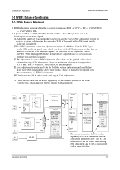
Alignment and Adjustments 2-2-2 White Balance Coordinates by Mode Pedestal Level Low Light measure point High Light measure point x H/L y Y( fL) x L/ L y Y( fL) DVI DTV COMPONENT PC (480P, 720P, 1080i ) 285 285 285 295 295 295 25 31.5 20.0 285 285 285 295 295 295 0.8 0.9 0.8 Pattern Used in Adjustment : 10 Steps Gray scale pattern VIDEO 280 295 31.5 285 300 0.9 2-6 Samsung Electronics
Alignment and Adjustments 2-2-2 White Balance Coordinates by Mode Pedestal Level Low Light measure point High Light measure point x H/L y Y( fL) x L/ L y Y( fL) DVI DTV COMPONENT PC (480P, 720P, 1080i ) 285 285 285 295 295 295 25 31.5 20.0 285 285 285 295 295 295 0.8 0.9 0.8 Pattern Used in Adjustment : 10 Steps Gray scale pattern VIDEO 280 295 31.5 285 300 0.9 2-6 Samsung Electronics
Service Manual
Page 9
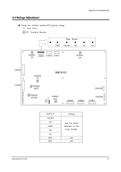
2-3 Voltage Adjustment Alignment and Adjustments Tuning the variabl e resistor(VR) adjusts voltage T : Te s t Point VR : Vari able Resistor Test Point VSET VSCAN VE VA VS T VR8601 VS CN830 CN806 CN811 VR8501 VA CN804 CN805 VR8540 VE SMPS-DC VR8580 VSET VR8560 VSCAN T D5V A6 V VR8491 D5V CN851B CN802 CN803 CN852B CN801 OUTPUT VSCAN VS VSET VE VA D5V A6V Voltage See the labels attached on the base chassis. +5V +6V Samsung Electronics 2-7
2-3 Voltage Adjustment Alignment and Adjustments Tuning the variabl e resistor(VR) adjusts voltage T : Te s t Point VR : Vari able Resistor Test Point VSET VSCAN VE VA VS T VR8601 VS CN830 CN806 CN811 VR8501 VA CN804 CN805 VR8540 VE SMPS-DC VR8580 VSET VR8560 VSCAN T D5V A6 V VR8491 D5V CN851B CN802 CN803 CN852B CN801 OUTPUT VSCAN VS VSET VE VA D5V A6V Voltage See the labels attached on the base chassis. +5V +6V Samsung Electronics 2-7

Service Manual
Page 11
Service Item 4-1 Assy Board & Part List for Service Electrical Parts List Samsung Electronics 4-1 4.
Service Item 4-1 Assy Board & Part List for Service Electrical Parts List Samsung Electronics 4-1 4.
Service Manual
Page 12
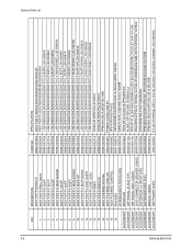
... ASSY PDP P-I BUFF ASSY PDP P-H BUFF ASSY PDP P-Y MAIN BOARD ASSY PDP P-Y BUFF UP ASSY PDP P-Y BUFF DOWN ASSY PDP P-LOGIC SUB R ASSY PDP P-LOGIC SUB L ASSY PDP P-SMPS ASSY PDP P-SMPS,DC ASSY PCB MISC-DIGITAL ASSY PCB MISC-ANALOG ASSY PCB MISC-CONTROL FAN-ASSY SCREEN-EMI,FILTER(GLASS) REMOCON CBF SIGNAL (D-SUB 15P) CBF SIGNAL (MDC CABLE) LEAD CONNECTOR (SEAKER CABLE) S/W DRIVER-7.0 (PIVOT S/W) S/W DRIVER (MDC S/W) MANUAL USERS CBF POWER CORD CODE...
... ASSY PDP P-I BUFF ASSY PDP P-H BUFF ASSY PDP P-Y MAIN BOARD ASSY PDP P-Y BUFF UP ASSY PDP P-Y BUFF DOWN ASSY PDP P-LOGIC SUB R ASSY PDP P-LOGIC SUB L ASSY PDP P-SMPS ASSY PDP P-SMPS,DC ASSY PCB MISC-DIGITAL ASSY PCB MISC-ANALOG ASSY PCB MISC-CONTROL FAN-ASSY SCREEN-EMI,FILTER(GLASS) REMOCON CBF SIGNAL (D-SUB 15P) CBF SIGNAL (MDC CABLE) LEAD CONNECTOR (SEAKER CABLE) S/W DRIVER-7.0 (PIVOT S/W) S/W DRIVER (MDC S/W) MANUAL USERS CBF POWER CORD CODE...
Service Manual
Page 13
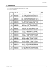
...,M3,S63HW-X 1 ASSY PDP P-Y BUFF DOWN;LJ92-00682A,M3,S6 1 ASSY PDP P-Y BUFF UP;LJ92-00681A,M3,S63H 1 ASSY PDP P-MODULE;M3,S63HW-XD02,D55A,D2. 1 ASSY PDP P-LOGIC MAIN BOARD;M3,S63HW-XD0 1 Samsung Electronics 4-3 URL:http://itself.sec.samsung.co.kr Electrical Parts List LOC.NO. 4-2 PPM63H3X/XSF Yon can search for the updated part code through ITSELF web site.
...,M3,S63HW-X 1 ASSY PDP P-Y BUFF DOWN;LJ92-00682A,M3,S6 1 ASSY PDP P-Y BUFF UP;LJ92-00681A,M3,S63H 1 ASSY PDP P-MODULE;M3,S63HW-XD02,D55A,D2. 1 ASSY PDP P-LOGIC MAIN BOARD;M3,S63HW-XD0 1 Samsung Electronics 4-3 URL:http://itself.sec.samsung.co.kr Electrical Parts List LOC.NO. 4-2 PPM63H3X/XSF Yon can search for the updated part code through ITSELF web site.
Service Manual
Page 15
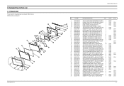
... 4 SCREW-TAPTITE;BH,+,B,M4,L15,ZPC(KHAKI),S 7 Loc.No. M0003 T0003 T0057 T0022 T0098 T0081 T0081 T0918 T0918 T0044 T0081 T0046 T0046 T0073 T0037 T0096 T0008 T0081 CCM1 T0243 EL013 T0132 T0145 CCM1 FT532 CCM1 T0001 T0081 CCM1 CCM1 CCM1 CCM1 T0081 S.N.A S.N.A S.N.A S.N.A S.N.A S.N.A S.N.A S.N.A S.N.A S.N.A T0081 S.N.A S.N.A S.N.A S.N.A S.N.A S.N.A S.N.A S.N.A S.N.A S.N.A S.N.A S.N.A S.N.A S.N.A S.N.A S.N.A 3-1 3. Exploded View & Parts List 3-1 PPM63H3X/XSF Yon can search for the updated part code...
... 4 SCREW-TAPTITE;BH,+,B,M4,L15,ZPC(KHAKI),S 7 Loc.No. M0003 T0003 T0057 T0022 T0098 T0081 T0081 T0918 T0918 T0044 T0081 T0046 T0046 T0073 T0037 T0096 T0008 T0081 CCM1 T0243 EL013 T0132 T0145 CCM1 FT532 CCM1 T0001 T0081 CCM1 CCM1 CCM1 CCM1 T0081 S.N.A S.N.A S.N.A S.N.A S.N.A S.N.A S.N.A S.N.A S.N.A S.N.A T0081 S.N.A S.N.A S.N.A S.N.A S.N.A S.N.A S.N.A S.N.A S.N.A S.N.A S.N.A S.N.A S.N.A S.N.A S.N.A S.N.A 3-1 3. Exploded View & Parts List 3-1 PPM63H3X/XSF Yon can search for the updated part code...

Service Manual
Page 16
Schematic Diagrams 5-1 ANALOG 1 Analog - 5. S-Video Video IN Video/S-Video Sound COMPONENT1 TP01 TP03 TP02 CXA2151Q IC103 Schematic Diagrams TP01 TP02 TP03 Samsung Electronics 5-1 Digital Board Connector This Document can not be used without Samsung's authorization.
Schematic Diagrams 5-1 ANALOG 1 Analog - 5. S-Video Video IN Video/S-Video Sound COMPONENT1 TP01 TP03 TP02 CXA2151Q IC103 Schematic Diagrams TP01 TP02 TP03 Samsung Electronics 5-1 Digital Board Connector This Document can not be used without Samsung's authorization.

Service Manual
Page 17
Schematic Diagrams 5-2 ANALOG 2 This Document can not be used without Samsung's authorization. 3D COMB FILTER R246 TILT SENSOR R247 FAN PART To DC FAN 50" 5-2 Samsung Electronics
Schematic Diagrams 5-2 ANALOG 2 This Document can not be used without Samsung's authorization. 3D COMB FILTER R246 TILT SENSOR R247 FAN PART To DC FAN 50" 5-2 Samsung Electronics
Service Manual
Page 18
5-3 ANALOG 3 TP05 TP04 TP06 TP07 MONITOR OUT VIDEO MONITOR OUT SOUND Samsung Electronics From SMPS Board Schematic Diagrams TP04 TP05 TP06 TP07 External Speaker This Document can not be used without Samsung's authorization. 5-3
5-3 ANALOG 3 TP05 TP04 TP06 TP07 MONITOR OUT VIDEO MONITOR OUT SOUND Samsung Electronics From SMPS Board Schematic Diagrams TP04 TP05 TP06 TP07 External Speaker This Document can not be used without Samsung's authorization. 5-3

Service Manual
Page 19
AA32-00013B 5-4 Samsung Electronics Schematic Diagrams 5-4 CONTROL This Document can not be used without Samsung's authorization.
AA32-00013B 5-4 Samsung Electronics Schematic Diagrams 5-4 CONTROL This Document can not be used without Samsung's authorization.

Service Manual
Page 22
5-7 SMPS 3 This Document can not be used without Samsung's authorization. Samsung Electronics Schematic Diagrams 5-7
5-7 SMPS 3 This Document can not be used without Samsung's authorization. Samsung Electronics Schematic Diagrams 5-7

Service Manual
Page 27
Schematic Diagrams 5-12 DIGITAL 1 This Document can not be used without Samsung's authorization. Digital board Connector PC(D-SUB&DVI) SOUND 5-12 42 SD 42 HD 50,63 HD TP08 TP09 TP10 TP08 TP09 TP10 Samsung Electronics Analog -
Schematic Diagrams 5-12 DIGITAL 1 This Document can not be used without Samsung's authorization. Digital board Connector PC(D-SUB&DVI) SOUND 5-12 42 SD 42 HD 50,63 HD TP08 TP09 TP10 TP08 TP09 TP10 Samsung Electronics Analog -

Service Manual
Page 28
5-13 DIGITAL 2 This Document can not be used without Samsung's authorization. PC D-SUB BNC Connector ANALOG EDID EPROM From SMPS board TP23 TP24 TP22 TP21 TP20 Samsung Electronics Schematic Diagrams TP20 TP21 TP22 TP23 TP24 5-13
5-13 DIGITAL 2 This Document can not be used without Samsung's authorization. PC D-SUB BNC Connector ANALOG EDID EPROM From SMPS board TP23 TP24 TP22 TP21 TP20 Samsung Electronics Schematic Diagrams TP20 TP21 TP22 TP23 TP24 5-13

Service Manual
Page 30
5-15 DIGITAL 4 This Document can not be used without Samsung's authorization. DVI Connector DIGITAL EDID EPROM Samsung Electronics Schematic Diagrams 5-15
5-15 DIGITAL 4 This Document can not be used without Samsung's authorization. DVI Connector DIGITAL EDID EPROM Samsung Electronics Schematic Diagrams 5-15

Service Manual
Page 32
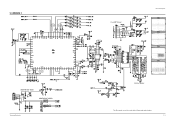
Schematic Diagrams 5-17 DIGITAL 6 This Document can not be used without Samsung's authorization. USER EPROM (256K) TP26 TP25 B12 : 1204-002105 RS232C OUT 5-17 RS232C IN Flash Memory Download Flash Memory From Remote Control board TP25 TP26 Samsung Electronics
Schematic Diagrams 5-17 DIGITAL 6 This Document can not be used without Samsung's authorization. USER EPROM (256K) TP26 TP25 B12 : 1204-002105 RS232C OUT 5-17 RS232C IN Flash Memory Download Flash Memory From Remote Control board TP25 TP26 Samsung Electronics


