
Open Source Guide (ENGLISH)
Page 1
... display an announcement including an appropriate copyright notice and a notice that is copyrighted by the Free Software Foundation. keep intact all the source code for this service if you wish), that you know that is interactive but may charge a fee for the physical act of the corresponding source code, to work for other Free Software Foundation software is true depends on the Program...
... display an announcement including an appropriate copyright notice and a notice that is copyrighted by the Free Software Foundation. keep intact all the source code for this service if you wish), that you know that is interactive but may charge a fee for the physical act of the corresponding source code, to work for other Free Software Foundation software is true depends on the Program...
Open Source Guide (ENGLISH)
Page 2
...use to the library. To apply these terms (or, alternatively, under these terms, attach the following notices to the public, we recommend making it free software that everyone can redistribute and change...USE OR INABILITY TO USE THE LIBRARY (INCLUDING BUT NOT LIMITED TO LOSS OF DATA OR DATA BEING RENDERED INACCURATE OR LOSSES SUSTAINED BY YOU OR THIRD PARTIES OR A FAILURE OF THE LIBRARY TO OPERATE WITH ANY OTHER SOFTWARE...), EVEN IF SUCH HOLDER OR OTHER PARTY HAS BEEN ADVISED OF THE POSSIBILITY OF SUCH DAMAGES. and each source file to where ...
...use to the library. To apply these terms (or, alternatively, under these terms, attach the following notices to the public, we recommend making it free software that everyone can redistribute and change...USE OR INABILITY TO USE THE LIBRARY (INCLUDING BUT NOT LIMITED TO LOSS OF DATA OR DATA BEING RENDERED INACCURATE OR LOSSES SUSTAINED BY YOU OR THIRD PARTIES OR A FAILURE OF THE LIBRARY TO OPERATE WITH ANY OTHER SOFTWARE...), EVEN IF SUCH HOLDER OR OTHER PARTY HAS BEEN ADVISED OF THE POSSIBILITY OF SUCH DAMAGES. and each source file to where ...

Quick Guide (easy Manual) (ver.1.0) (English)
Page 6
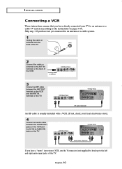
... to an antenna or a cable TV system (according to the left and right audio input jacks of the TV. English-6 VCR Rear Panel TV Rear Panel Audio Cable If you have a "mono" (non-stereo) VCR, use the Y-connector (not supplied) to hook up to the instructions on the TV. 01 BN68-00816A-00.qxd 2/1/05 4:14 PM Page 10 I N S TA L L AT I O N Connecting a VCR These instructions assume...
... to an antenna or a cable TV system (according to the left and right audio input jacks of the TV. English-6 VCR Rear Panel TV Rear Panel Audio Cable If you have a "mono" (non-stereo) VCR, use the Y-connector (not supplied) to hook up to the instructions on the TV. 01 BN68-00816A-00.qxd 2/1/05 4:14 PM Page 10 I N S TA L L AT I O N Connecting a VCR These instructions assume...

Quick Guide (easy Manual) (ver.1.0) (English)
Page 8
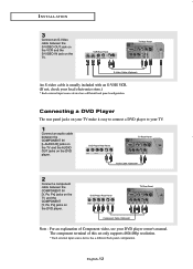
... a DVD Player The rear panel jacks on the DVD player. The component terminal of Component video, see your TV. 1 Connect an audio cable between the COMPONENT IN [L-AUDIO-R] jacks on the TV and the AUDIO OUT jacks on your TV make it easy to connect a DVD player to your DVD player owner's manual. DVD Player Rear Panel TV Rear Panel Component Cable Note : For an explanation of this set only supports 480i/480p resolution. * Each external input source device has a different back panel configuration. DVD Player Rear Panel TV Rear Panel Audio Cable 2 Connect a component cable between...
... a DVD Player The rear panel jacks on the DVD player. The component terminal of Component video, see your TV. 1 Connect an audio cable between the COMPONENT IN [L-AUDIO-R] jacks on the TV and the AUDIO OUT jacks on your TV make it easy to connect a DVD player to your DVD player owner's manual. DVD Player Rear Panel TV Rear Panel Component Cable Note : For an explanation of this set only supports 480i/480p resolution. * Each external input source device has a different back panel configuration. DVD Player Rear Panel TV Rear Panel Audio Cable 2 Connect a component cable between...
Quick Guide (easy Manual) (ver.1.0) (English)
Page 10
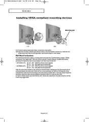
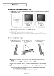
... wall mount bracket kit. • LN-R1550 (15") : No. 47 - 007 - 099 (Pivot direct mount adapter) No. 97 - 101 - 003 (Wall mount bracket kit) • LN-R2050 (20") : No. 47 - 007 - 099 (Pivot direct mount adapter) No. 97 - 101 - 003 (Wall mount bracket kit) Align the wall mount bracket on the back of the TV using four 3/16 by 3-inch long toggle bolts. Secure the assembly to the wall using the four 4mm, 0.7 pitch x 10mm screws...
... wall mount bracket kit. • LN-R1550 (15") : No. 47 - 007 - 099 (Pivot direct mount adapter) No. 97 - 101 - 003 (Wall mount bracket kit) • LN-R2050 (20") : No. 47 - 007 - 099 (Pivot direct mount adapter) No. 97 - 101 - 003 (Wall mount bracket kit) Align the wall mount bracket on the back of the TV using four 3/16 by 3-inch long toggle bolts. Secure the assembly to the wall using the four 4mm, 0.7 pitch x 10mm screws...

Quick Guide (easy Manual) (ver.1.0) (English)
Page 11
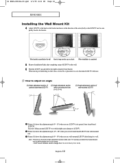
..., please contact your nearest dealer. Components Please use LCD TV right after fixing it to the wall since stand is not firmly fixed to the wall, LCD TV can fall off. 2 You may use provided components or parts to install the Wall Mount Kit. depth- Bracket Anchors : 3EA Screws : 3EA Installation Guide How to assemble the Wall Mount Kit 1 Mark the location of hole on the marked location using installation guide. Then turn over 35mm- 04 BN68-00816A...
..., please contact your nearest dealer. Components Please use LCD TV right after fixing it to the wall since stand is not firmly fixed to the wall, LCD TV can fall off. 2 You may use provided components or parts to install the Wall Mount Kit. depth- Bracket Anchors : 3EA Screws : 3EA Installation Guide How to assemble the Wall Mount Kit 1 Mark the location of hole on the marked location using installation guide. Then turn over 35mm- 04 BN68-00816A...
Quick Guide (easy Manual) (ver.1.0) (English)
Page 12
... APPENDIX Installing the Wall Mount Kit 4 Adjust LCD TV to the hook on the bracket and move in its general form (stand-based LCD TV). Picture (3) shows the adjustment angle (0°~ 10°) when you use wall-mounted LCD TV after completing setup of the arrow(Left) so that LCD TV can turn LCD TV over which might cause damage to 2 (1->2, 3->2). When bracket is completed 5 Remove Installation Guide after fixing it to detach it from stand-based...
... APPENDIX Installing the Wall Mount Kit 4 Adjust LCD TV to the hook on the bracket and move in its general form (stand-based LCD TV). Picture (3) shows the adjustment angle (0°~ 10°) when you use wall-mounted LCD TV after completing setup of the arrow(Left) so that LCD TV can turn LCD TV over which might cause damage to 2 (1->2, 3->2). When bracket is completed 5 Remove Installation Guide after fixing it to detach it from stand-based...
Quick Guide (easy Manual) (ver.1.0) (English)
Page 4
... All Channels . . .8 Connecting to a Cable Box that Descrambles Some Channels . .8 Connecting a PC 9 Connecting a VCR 10 Connecting an S-VHS VCR 11 Connecting a DVD Player 12 Chapter 3: Special Features Turning the TV On and Off 13 Changing Channels 13 Using the Channel Buttons 13 Using the PRE-CH Button to select the Previous Channel . .13 Adjusting the Volume 13 Using Mute 13 Viewing the Display 14 Viewing the Menus 14 Chapter 4: Operation Plug & Play Feature 15 Memorizing the Channels 16 Selecting the Video Signal-source...
... All Channels . . .8 Connecting to a Cable Box that Descrambles Some Channels . .8 Connecting a PC 9 Connecting a VCR 10 Connecting an S-VHS VCR 11 Connecting a DVD Player 12 Chapter 3: Special Features Turning the TV On and Off 13 Changing Channels 13 Using the Channel Buttons 13 Using the PRE-CH Button to select the Previous Channel . .13 Adjusting the Volume 13 Using Mute 13 Viewing the Display 14 Viewing the Menus 14 Chapter 4: Operation Plug & Play Feature 15 Memorizing the Channels 16 Selecting the Video Signal-source...
Quick Guide (easy Manual) (ver.1.0) (English)
Page 5
... Set up Your PC Software (Windows only 45 Adjusting the Screen Quality 46 Changing the Screen Position 47 To Initialize the Screen Position or Color Settings 48 How to Auto Adjust 49 Using Automatic Picture Settings 50 Customizing the Picture 51 Adjusting the Color Tone 52 Customizing the Color 53 Chapter 6: Troubleshooting Identifying Problems 54 Appendix Using the Anti-Theft Kensington Lock 56 Retractable Stand 57 Installing VESA compliant mounting devices 58 Installing the Wall Mount Kit 59 Display Mode 61 Using...
... Set up Your PC Software (Windows only 45 Adjusting the Screen Quality 46 Changing the Screen Position 47 To Initialize the Screen Position or Color Settings 48 How to Auto Adjust 49 Using Automatic Picture Settings 50 Customizing the Picture 51 Adjusting the Color Tone 52 Customizing the Color 53 Chapter 6: Troubleshooting Identifying Problems 54 Appendix Using the Anti-Theft Kensington Lock 56 Retractable Stand 57 Installing VESA compliant mounting devices 58 Installing the Wall Mount Kit 59 Display Mode 61 Using...
Quick Guide (easy Manual) (ver.1.0) (English)
Page 6
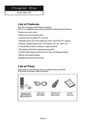
... sharpest picture possible • A built-in multi-channel sound decoder for stereo and bilingual listening • Built-in, dual channel speakers • Headphone jack for private listening List of Features Your TV was designed with your dealer. If any items are included with the latest technology. Remote Control (BN59-00429A) & Batteries (AAA x 2) Power Cord 3903-000085 Wall Mount kit BN96-01270A Owner's Instructions English...
... sharpest picture possible • A built-in multi-channel sound decoder for stereo and bilingual listening • Built-in, dual channel speakers • Headphone jack for private listening List of Features Your TV was designed with your dealer. If any items are included with the latest technology. Remote Control (BN59-00429A) & Batteries (AAA x 2) Power Cord 3903-000085 Wall Mount kit BN96-01270A Owner's Instructions English...
Quick Guide (easy Manual) (ver.1.0) (English)
Page 7
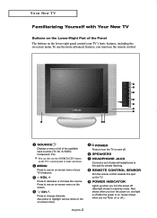
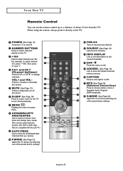
... screen. Press to turn the power on, and light is off after the power is on and off .) CH Press to make selections. To use the more advanced features, you turn the TV on . POWER INDICATOR Lights up when you turn the power off. (Red light shows in stand-by mode, Red shows when you must use the SOURCE( ) button on or off . SPEAKERS HEADPHONE JACK Connect a set Timer on the TV's control panel to change channels...
... screen. Press to turn the power on, and light is off after the power is on and off .) CH Press to make selections. To use the more advanced features, you turn the TV on . POWER INDICATOR Lights up when you turn the power off. (Red light shows in stand-by mode, Red shows when you must use the SOURCE( ) button on or off . SPEAKERS HEADPHONE JACK Connect a set Timer on the TV's control panel to change channels...
Quick Guide (easy Manual) (ver.1.0) (English)
Page 9
... Press the menu to turn off the sound. VOL+ and VOLPress to see information on -screen menu items and change channels. English-4 SOURCE (See Page 19) Input source selection INFO DISPLAY Use to increase or decrease the volume. When using the remote, always point it directly at the TV. For example, to store the broadcast/cable channels that are compatible with the LCD TV.) AUTO PROG. Use to select channel 121, press...
... Press the menu to turn off the sound. VOL+ and VOLPress to see information on -screen menu items and change channels. English-4 SOURCE (See Page 19) Input source selection INFO DISPLAY Use to increase or decrease the volume. When using the remote, always point it directly at the TV. For example, to store the broadcast/cable channels that are compatible with the LCD TV.) AUTO PROG. Use to select channel 121, press...
Quick Guide (easy Manual) (ver.1.0) (English)
Page 15
... supplied) to hook up to the left and right audio input jacks of the VCR. Skip step 1 if you have already connected your local electronics store). 4 Connect an audio cable between the ANT OUT terminal on the VCR and the ANT IN terminal on the back of the TV. VCR Rear Panel TV Rear Panel Audio Cable If you have not yet connected to an antenna...
... supplied) to hook up to the left and right audio input jacks of the VCR. Skip step 1 if you have already connected your local electronics store). 4 Connect an audio cable between the ANT OUT terminal on the VCR and the ANT IN terminal on the back of the TV. VCR Rear Panel TV Rear Panel Audio Cable If you have not yet connected to an antenna...
Quick Guide (easy Manual) (ver.1.0) (English)
Page 17
... electronics store.) * Each external input source device has a different back panel configuration. DVD Player Rear Panel TV Rear Panel Component Cable Note : For an explanation of this set only supports 480i/480p resolution. * Each external input source device has a different back panel configuration. VCR Rear Panel TV Rear Panel S-Video Cable An S-video cable is usually included with an S-VHS VCR. (If not, check your DVD player owner's manual. DVD Player Rear Panel TV Rear Panel Audio Cable 2 Connect a component cable between the COMPONENT IN [L-AUDIO-R] jacks on the...
... electronics store.) * Each external input source device has a different back panel configuration. DVD Player Rear Panel TV Rear Panel Component Cable Note : For an explanation of this set only supports 480i/480p resolution. * Each external input source device has a different back panel configuration. VCR Rear Panel TV Rear Panel S-Video Cable An S-video cable is usually included with an S-VHS VCR. (If not, check your DVD player owner's manual. DVD Player Rear Panel TV Rear Panel Audio Cable 2 Connect a component cable between the COMPONENT IN [L-AUDIO-R] jacks on the...
Quick Guide (easy Manual) (ver.1.0) (English)
Page 19
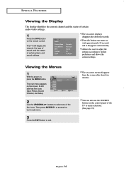
Viewing the Menus 1 With the power on the remote control. Its left side has five icons: Input, Picture, Sound, Channel, and Setup. 2 Use the UP/DOWN buttons to exit. Then press ENTER to access the icon's sub-menu. 3 Press the EXIT button to select one of the five icons. You can also use the SOURCE buttons on -screen displays disappear after about ten seconds. The on the control panel of the TV...
Viewing the Menus 1 With the power on the remote control. Its left side has five icons: Input, Picture, Sound, Channel, and Setup. 2 Use the UP/DOWN buttons to exit. Then press ENTER to access the icon's sub-menu. 3 Press the EXIT button to select one of the five icons. You can also use the SOURCE buttons on -screen displays disappear after about ten seconds. The on the control panel of the TV...
Quick Guide (easy Manual) (ver.1.0) (English)
Page 59
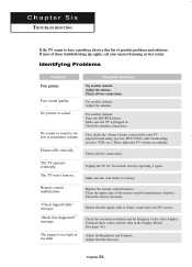
... resolution and the frequency of the remote control (transmission window). Adjust the antenna. Try another channel. Check all wire connections. "Mode Not Supported!" Picture rolls vertically. Press the SOURCE button. Unplug the TV for 30 seconds, then try this list of these values with the data in . Ensure that the signal cable is firmly connected to your nearest Samsung service center. The TV won't turn on. Make sure the wall...
... resolution and the frequency of the remote control (transmission window). Adjust the antenna. Try another channel. Check all wire connections. "Mode Not Supported!" Picture rolls vertically. Press the SOURCE button. Unplug the TV for 30 seconds, then try this list of these values with the data in . Ensure that the signal cable is firmly connected to your nearest Samsung service center. The TV won't turn on. Make sure the wall...
Quick Guide (easy Manual) (ver.1.0) (English)
Page 60
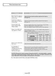
... check: Power, Signal Cable (15-pin D-Sub) The TV is not correct, use your computer utility program to change the display settings. However, there may appear to display moving images. Note : The component terminal of time, adjust the settings so that the monitor automatically goes into energy saving mode or activates the screen saver to vibrate. If the setting is using its power management system. When you need to flicker...
... check: Power, Signal Cable (15-pin D-Sub) The TV is not correct, use your computer utility program to change the display settings. However, there may appear to display moving images. Note : The component terminal of time, adjust the settings so that the monitor automatically goes into energy saving mode or activates the screen saver to vibrate. If the setting is using its power management system. When you need to flicker...
Quick Guide (easy Manual) (ver.1.0) (English)
Page 63
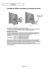
.... Tools/Hardware needed - Securely attach Ergotron's flat panel, triple pivot direct mount adapter to the back of the stand. Secure the assembly to the wall using the four 4mm, 0.7 pitch x 10mm screws provided with it with the four screws that the bracket will be mounted between the wall studs. Mark the four corner openings and drill four 5/8-diameter holes. APPENDIX Installing VESA compliant mounting devices Mounting pad Fold...
.... Tools/Hardware needed - Securely attach Ergotron's flat panel, triple pivot direct mount adapter to the back of the stand. Secure the assembly to the wall using the four 4mm, 0.7 pitch x 10mm screws provided with it with the four screws that the bracket will be mounted between the wall studs. Mark the four corner openings and drill four 5/8-diameter holes. APPENDIX Installing VESA compliant mounting devices Mounting pad Fold...
Quick Guide (easy Manual) (ver.1.0) (English)
Page 65
... in its general form (stand-based LCD TV). English-60 APPENDIX Installing the Wall Mount Kit 4 Adjust LCD TV to the hook on the wall. 6 Push the LCD TV up on a hook When installation is completed 5 Remove Installation Guide after fixing it from bracket. When bracket is assembled on the wall How to hang monitor up and shift to the right to detach it to wall. Click" sound indicates section change from 1 to 2 or 3 to...
... in its general form (stand-based LCD TV). English-60 APPENDIX Installing the Wall Mount Kit 4 Adjust LCD TV to the hook on the wall. 6 Push the LCD TV up on a hook When installation is completed 5 Remove Installation Guide after fixing it from bracket. When bracket is assembled on the wall How to hang monitor up and shift to the right to detach it to wall. Click" sound indicates section change from 1 to 2 or 3 to...
Quick Guide (easy Manual) (ver.1.0) (English)
Page 67
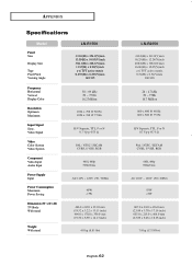
Video Signal Video Color System Video System Component Video Input Audio Input Power Supply Input Power Consumption Maximum Power Saving Dimension (W x D x H) TV Body With stand Weight With stand 30 ~ 69 kHz 50 ~ 75 Hz 16.2 Million 1024 x 768 @ 60 Hz 1024 x 768 @ 75 Hz H/V Separate, TTL, P or N 0.7 Vp-p @75 Ω PAL / NTSC / SECAM CVBS, S-VHS, RGB 480i, 480p 500mVrms AC 110V ~ 120V (50 / 60Hz) 40W APPENDIX Specifications Model Panel Size Display Size Type Pixel Pitch Viewing Angle LN-R1550...
Video Signal Video Color System Video System Component Video Input Audio Input Power Supply Input Power Consumption Maximum Power Saving Dimension (W x D x H) TV Body With stand Weight With stand 30 ~ 69 kHz 50 ~ 75 Hz 16.2 Million 1024 x 768 @ 60 Hz 1024 x 768 @ 75 Hz H/V Separate, TTL, P or N 0.7 Vp-p @75 Ω PAL / NTSC / SECAM CVBS, S-VHS, RGB 480i, 480p 500mVrms AC 110V ~ 120V (50 / 60Hz) 40W APPENDIX Specifications Model Panel Size Display Size Type Pixel Pitch Viewing Angle LN-R1550...


