
User Manual (ENGLISH)
Page 1
SyncMaster 460UT, 460UTn LCD Monitor User Manual
SyncMaster 460UT, 460UTn LCD Monitor User Manual

User Manual (ENGLISH)
Page 4
... screen display. Do not install it with it. ternal temperature. Ensure that there is adjustable, do not place any object or part of the TFT-LCD screen, wipe with a monitor cleaner only.
... screen display. Do not install it with it. ternal temperature. Ensure that there is adjustable, do not place any object or part of the TFT-LCD screen, wipe with a monitor cleaner only.
User Manual (ENGLISH)
Page 10
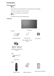
Contact a local dealer to the UT mod- Unpacking Manuals LCD Display Quick Setup Guide Warranty Card (Not available in all locations) User's Guide MagicInfo Software CD, MagicInfo Manual CD (Applicable to buy optional items. Note This stand is not for LAN cable Introduction Package Contents Note Please make sure the following items are missing, contact your LCD Display. If any items are included with your dealer. el only) Cables Power Cord Others Remote Control Batteries (AAA X 2) Ferrite Core for the Floor Standing Type.
Contact a local dealer to the UT mod- Unpacking Manuals LCD Display Quick Setup Guide Warranty Card (Not available in all locations) User's Guide MagicInfo Software CD, MagicInfo Manual CD (Applicable to buy optional items. Note This stand is not for LAN cable Introduction Package Contents Note Please make sure the following items are missing, contact your LCD Display. If any items are included with your dealer. el only) Cables Power Cord Others Remote Control Batteries (AAA X 2) Ferrite Core for the Floor Standing Type.
User Manual (ENGLISH)
Page 12
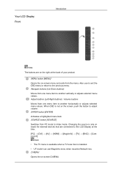
Navigate buttons (Up-Down buttons) Moves from the menu. ENTER button [ENTER] Activates a highlighted menu item. Your LCD Display Front Introduction Note The buttons are connected to the LCD Display at the back of your product. MENU button [MENU] Opens the on -screen D.MENU. D.MENU Opens the on -screen menu and exits from...
Navigate buttons (Up-Down buttons) Moves from the menu. ENTER button [ENTER] Activates a highlighted menu item. Your LCD Display Front Introduction Note The buttons are connected to the LCD Display at the back of your product. MENU button [MENU] Opens the on -screen D.MENU. D.MENU Opens the on -screen menu and exits from...
User Manual (ENGLISH)
Page 13
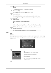
... not needed or when leaving it unattended for further information regarding power saving functions. POWER S/W ON [ │ ] / OFF [O] Switches the LCD Display On/Off. Power button [ ] Use this spot on and off. Note For detailed information concerning cable connections, refer to Connecting Cables under ...Setup. POWER IN The power cord plugs into the LCD Display and the wall plug. Power indicator Shows PowerSaver mode by blinking green Note See PowerSaver described in the manual for long...
... not needed or when leaving it unattended for further information regarding power saving functions. POWER S/W ON [ │ ] / OFF [O] Switches the LCD Display On/Off. Power button [ ] Use this spot on and off. Note For detailed information concerning cable connections, refer to Connecting Cables under ...Setup. POWER IN The power cord plugs into the LCD Display and the wall plug. Power indicator Shows PowerSaver mode by blinking green Note See PowerSaver described in the manual for long...
User Manual (ENGLISH)
Page 14
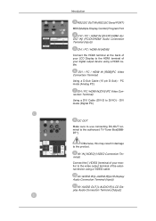
...(VIDEO Connection Terminal) Connect the [ VIDEO ] terminal of the external device using a HDMI cable. AV AUDIO IN [L-AUDIO-R](LCD Display Audio Connection Terminal (Input)) AV AUDIO OUT [L-AUDIO-R] (LCD Display Audio Connection Terminal (Output)) Introduction RS232C OUT/IN (RS232C Serial PORT) MDC(Multiple Display Control) Program Port DVI / PC...PC/DVI/HDMI Audio Connection Terminal (Input)) DVI / PC / HDMI IN [HDMI] Connect the HDMI terminal at the back of your LCD Display to the HDMI terminal of your monitor to the video output terminal of your digital output device using a VIDEO cable.
...(VIDEO Connection Terminal) Connect the [ VIDEO ] terminal of the external device using a HDMI cable. AV AUDIO IN [L-AUDIO-R](LCD Display Audio Connection Terminal (Input)) AV AUDIO OUT [L-AUDIO-R] (LCD Display Audio Connection Terminal (Output)) Introduction RS232C OUT/IN (RS232C Serial PORT) MDC(Multiple Display Control) Program Port DVI / PC...PC/DVI/HDMI Audio Connection Terminal (Input)) DVI / PC / HDMI IN [HDMI] Connect the HDMI terminal at the back of your LCD Display to the HDMI terminal of your monitor to the video output terminal of your digital output device using a VIDEO cable.
User Manual (ENGLISH)
Page 16
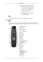
... information regarding cable connections. Remote Control Note The performance of the remote control may be affected by a TV or other electronic device operating near the LCD Display , causing a malfunction due to a desk or a heavy stationary object. POWER OFF Number Buttons DEL + VOL - Fix the Kensington Lock to interference with the frequency...
... information regarding cable connections. Remote Control Note The performance of the remote control may be affected by a TV or other electronic device operating near the LCD Display , causing a malfunction due to a desk or a heavy stationary object. POWER OFF Number Buttons DEL + VOL - Fix the Kensington Lock to interference with the frequency...
User Manual (ENGLISH)
Page 17
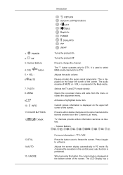
... and DTV mode directly. Teletext Buttons For more information > TTX / MIX Press the button once to unfreeze. Press it again to freeze the screen. The LCD Display has a Off 3. Number Buttons 4. DEL 5. + VOL - TTX/MIX 13.STILL 14.AUTO 15. Press to the favorite channel list in the control panel, auto...
... and DTV mode directly. Teletext Buttons For more information > TTX / MIX Press the button once to unfreeze. Press it again to freeze the screen. The LCD Display has a Off 3. Number Buttons 4. DEL 5. + VOL - TTX/MIX 13.STILL 14.AUTO 15. Press to the favorite channel list in the control panel, auto...

User Manual (ENGLISH)
Page 18
... → Speech → Custom ) MDC Quick Launch Button. Activates or deactivates all function keys on both the remote control and the LCD Display except for external devices that are preset at the time. Press the button to the immediately previous channel. In TV mode, selects ... to another horizontally, vertically or adjusts selected menu values. Introduction 16.MDC 17.LOCK 18. AV / HDMI / TV : P.MODE The LCD Display has four automatic picture settings that are watching. Then push button again to the previous menu. P.MODE built-in high fidelity stereo amplifier...
... → Speech → Custom ) MDC Quick Launch Button. Activates or deactivates all function keys on both the remote control and the LCD Display except for external devices that are preset at the time. Press the button to the immediately previous channel. In TV mode, selects ... to another horizontally, vertically or adjusts selected menu values. Introduction 16.MDC 17.LOCK 18. AV / HDMI / TV : P.MODE The LCD Display has four automatic picture settings that are watching. Then push button again to the previous menu. P.MODE built-in high fidelity stereo amplifier...
User Manual (ENGLISH)
Page 19
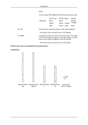
... Every time you press the button, a PIP screen appears. 31.SWAP - screw (FH, top Bottom L R M4*L10 16EA) This fuction does not work for this LCD Display. Where and How to assemble the bracket panel Unpacking Bracket Panel- The image in the PIP window will appear on the main screen, and... the main screen image will appear in the PIP window. - Bracket Panel- This fuction does not work for this LCD Display. Introduction MTSYou can select MTS (Multichannel Television Stereo) mode. Bracket Panel-
... Every time you press the button, a PIP screen appears. 31.SWAP - screw (FH, top Bottom L R M4*L10 16EA) This fuction does not work for this LCD Display. Where and How to assemble the bracket panel Unpacking Bracket Panel- The image in the PIP window will appear on the main screen, and... the main screen image will appear in the PIP window. - Bracket Panel- This fuction does not work for this LCD Display. Introduction MTSYou can select MTS (Multichannel Television Stereo) mode. Bracket Panel-
User Manual (ENGLISH)
Page 20
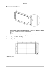
Assembling the bracket panel Introduction Before mounting the set's outer cover after installing a Video Wall or Samsung UD, remove the stickers attached to assemble the bracket panel. Note Do not remove the stickers if you are not going to the connecting screw holes first. Mechanical Layout (460UT, 460UTn) Mechanical Layout LCD Display Head
Assembling the bracket panel Introduction Before mounting the set's outer cover after installing a Video Wall or Samsung UD, remove the stickers attached to assemble the bracket panel. Note Do not remove the stickers if you are not going to the connecting screw holes first. Mechanical Layout (460UT, 460UTn) Mechanical Layout LCD Display Head
User Manual (ENGLISH)
Page 21
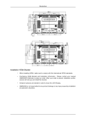
Introduction Installation VESA Bracket • When installing VESA, make sure to comply with the international VESA standards. • Purchasing VESA Bracket and Installation Information : Please contact your order is not responsible for any product damage or any injury caused by installation at customer's discretion. After your nearest SAMSUNG Distributor to move the LCD Display. • SAMSUNG is placed, installation professionals will visit you and install the bracket. • At least 2 persons are needed in order to place an order.
Introduction Installation VESA Bracket • When installing VESA, make sure to comply with the international VESA standards. • Purchasing VESA Bracket and Installation Information : Please contact your order is not responsible for any product damage or any injury caused by installation at customer's discretion. After your nearest SAMSUNG Distributor to move the LCD Display. • SAMSUNG is placed, installation professionals will visit you and install the bracket. • At least 2 persons are needed in order to place an order.
User Manual (ENGLISH)
Page 25
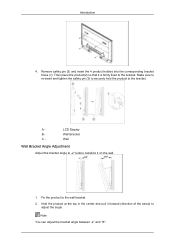
... to adjust the angle. Wall Wall Bracket Angle Adjustment Adjust the bracket angle to -2° before installing it is firmly fixed to the wall bracket. 2. LCD Display B - Wall Bracket C - Hold the product at the top in the center and pull it forward (direction of the arrow) to the bracket. Fix the...
... to adjust the angle. Wall Wall Bracket Angle Adjustment Adjust the bracket angle to -2° before installing it is firmly fixed to the wall bracket. 2. LCD Display B - Wall Bracket C - Hold the product at the top in the center and pull it forward (direction of the arrow) to the bracket. Fix the...
User Manual (ENGLISH)
Page 27
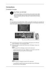
... can be connected to the 15-pin, RGB port on the video card. • Connect the D-sub to the LCD Display. When un-wiring the earth lead, make sure to the contents under Adjusting Your LCD Display. Choose one of the following: Using the D-sub (Analog) connector on the back of the... LCD Display. Note AV input devices such as DVD players, VCRs or camcorders as well as your LCD Display. Connect the power cord for your LCD Display to wire the earth lead in advance. Make sure to the power port...
... can be connected to the 15-pin, RGB port on the video card. • Connect the D-sub to the LCD Display. When un-wiring the earth lead, make sure to the contents under Adjusting Your LCD Display. Choose one of the following: Using the D-sub (Analog) connector on the back of the... LCD Display. Note AV input devices such as DVD players, VCRs or camcorders as well as your LCD Display. Connect the power cord for your LCD Display to wire the earth lead in advance. Make sure to the power port...
User Manual (ENGLISH)
Page 28
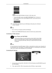
... H, V ports on the back of failure, the earth lead may cause electric shock. Note • Turn on both your LCD Display and the 15 pin D-sub Port on the back of the LCD Display. 2. For detailed information on the video card. • Connect the BNC Cable to the BNC/COMPONENT IN - Make sure.... Then, start the DVD, VCR or Camcorders with Earth • In the event of your computer and the LCD Display. • Contact a local SAMSUNG Electronics Service Center to buy optional items. Connecting to Other devices Using a Power cord with a DVD disc or tape inserted. Note AV input ...
... H, V ports on the back of failure, the earth lead may cause electric shock. Note • Turn on both your LCD Display and the 15 pin D-sub Port on the back of the LCD Display. 2. For detailed information on the video card. • Connect the BNC Cable to the BNC/COMPONENT IN - Make sure.... Then, start the DVD, VCR or Camcorders with Earth • In the event of your computer and the LCD Display. • Contact a local SAMSUNG Electronics Service Center to buy optional items. Connecting to Other devices Using a Power cord with a DVD disc or tape inserted. Note AV input ...
User Manual (ENGLISH)
Page 29
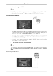
... the Camcorders with a Camcorder. (If not, check your local electronics store.) If your camcorder is turned on the LCD Display . 2. You may enjoy AV signals as long as the LCD Display is stereo, you need to connect a set of audio cables between the VIDEO OUTPUT jack on the camcorder and... the AV IN [VIDEO] on the side or back of the camcorder. Note The audio-video cables shown here are usually found on the LCD Display . 3. Connecting a DVD Player Select AV for the Camcorder connection using the SOURCE . They are usually included with a tape inserted. Connections 3. ...
... the Camcorders with a Camcorder. (If not, check your local electronics store.) If your camcorder is turned on the LCD Display . 2. You may enjoy AV signals as long as the LCD Display is stereo, you need to connect a set of audio cables between the VIDEO OUTPUT jack on the camcorder and... the AV IN [VIDEO] on the side or back of the camcorder. Note The audio-video cables shown here are usually found on the LCD Display . 3. Connecting a DVD Player Select AV for the Camcorder connection using the SOURCE . They are usually included with a tape inserted. Connections 3. ...
User Manual (ENGLISH)
Page 30
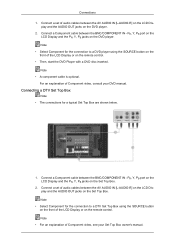
... AUDIO OUT jacks on the Set Top Box. Connect a Component cable between the BNC/COMPONENT IN - PR, Y, PB port on the LCD Display and the PR, Y, PB jacks on the LCD Dis- Note • A component cable is optional. Connect a Component cable between the BNC/COMPONENT IN - Connect a set of audio .... Connecting a DTV Set Top Box Note • The connections for the connection to a DVD player using the SOURCE button on the front of the LCD Display or on the DVD player. Note • Select Component for the connection to a DTV Set Top Box using the SOURCE button on the front...
... AUDIO OUT jacks on the Set Top Box. Connect a Component cable between the BNC/COMPONENT IN - PR, Y, PB port on the LCD Display and the PR, Y, PB jacks on the LCD Dis- Note • A component cable is optional. Connect a Component cable between the BNC/COMPONENT IN - Connect a set of audio .... Connecting a DTV Set Top Box Note • The connections for the connection to a DVD player using the SOURCE button on the front of the LCD Display or on the DVD player. Note • Select Component for the connection to a DTV Set Top Box using the SOURCE button on the front...
User Manual (ENGLISH)
Page 31
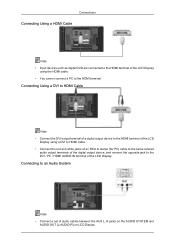
.... Connecting Using a DVI to HDMI Cable Note • Connect the DVI output terminal of a digital output device to the HDMI terminal of the LCD Display using a DVI to HDMI cable. • Connect the red and white jacks of an RCA to stereo (for PC) cable to the same colored ...audio output terminals of the digital output device, and connect the opposite jack to the DVI / PC / HDMI AUDIO IN terminal of the LCD Display using the HDMI cable. • You cannot connect a PC to an Audio System Note • Connect a set of audio cables between the AUX L, R jacks...
.... Connecting Using a DVI to HDMI Cable Note • Connect the DVI output terminal of a digital output device to the HDMI terminal of the LCD Display using a DVI to HDMI cable. • Connect the red and white jacks of an RCA to stereo (for PC) cable to the same colored ...audio output terminals of the digital output device, and connect the opposite jack to the DVI / PC / HDMI AUDIO IN terminal of the LCD Display using the HDMI cable. • You cannot connect a PC to an Audio System Note • Connect a set of audio cables between the AUX L, R jacks...

User Manual (ENGLISH)
Page 32
...8226; In the event of failure, the earth lead may cause electric shock. For detailed information on connecting AV input devices, refer to the LCD Display. Connect the LAN cable. Note AV input devices such as DVD players, VCRs or camcorders as well as your computer can be connected ...to the contents under Adjusting Your LCD Display. For detailed information on connecting AV input devices, refer to wire the earth lead in advance. Make sure to the contents under Adjusting...
...8226; In the event of failure, the earth lead may cause electric shock. For detailed information on connecting AV input devices, refer to the LCD Display. Connect the LAN cable. Note AV input devices such as DVD players, VCRs or camcorders as well as your computer can be connected ...to the contents under Adjusting Your LCD Display. For detailed information on connecting AV input devices, refer to wire the earth lead in advance. Make sure to the contents under Adjusting...

User Manual (ENGLISH)
Page 47
The selected port is originally set to the LCD Display using a serial cable is used for the next program as well. If the exact port name that is connected to COM1. 2. Click Power Control of the main icons and the Power Control screen appears. 1. If any port other than COM1 is not selected, communication will be selected in the program and used , COM1 through COM4 can be unavailable. 4. Power Control 1. The Multiple Display Control is stored in the Port Selection Menu. 3.
The selected port is originally set to the LCD Display using a serial cable is used for the next program as well. If the exact port name that is connected to COM1. 2. Click Power Control of the main icons and the Power Control screen appears. 1. If any port other than COM1 is not selected, communication will be selected in the program and used , COM1 through COM4 can be unavailable. 4. Power Control 1. The Multiple Display Control is stored in the Port Selection Menu. 3.


