User Manual
Page 1
SyncMaster 400MX-3, 460MX-3, 400FP-3, 460FP-3 LCD Display User Manuals The color and the appearance may differ depending on the product, and the specifications are subject to change without prior notice to improve the performance.
SyncMaster 400MX-3, 460MX-3, 400FP-3, 460FP-3 LCD Display User Manuals The color and the appearance may differ depending on the product, and the specifications are subject to change without prior notice to improve the performance.
User Manual
Page 5
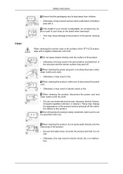
.... • Otherwise, it may result in serious harm (suffocation) if children play with it. Do not spray cleaner directly onto the surface of the TFT-LCD screen, wipe with a dry cloth. • Otherwise, it may change the appearance of the product surface and peel off . When cleaning the product, make sure...
.... • Otherwise, it may result in serious harm (suffocation) if children play with it. Do not spray cleaner directly onto the surface of the TFT-LCD screen, wipe with a dry cloth. • Otherwise, it may change the appearance of the product surface and peel off . When cleaning the product, make sure...
User Manual
Page 10
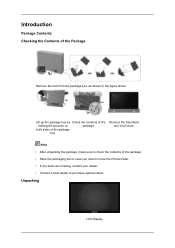
Note • After unpacking the package, make sure to purchase optional items. Unpacking LCD Display Remove the Styrofoam and vinyl cover. both sides of the package. • Store the packaging box in the figure above. Lift up the package ...
Note • After unpacking the package, make sure to purchase optional items. Unpacking LCD Display Remove the Styrofoam and vinyl cover. both sides of the package. • Store the packaging box in the figure above. Lift up the package ...
User Manual
Page 12
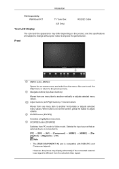
.... SOURCE button [SOURCE] Switches from PC mode to the previous menu. Introduction Sold separately Wall Mount KIT TV Tuner box (US Only) RS232C Cable Your LCD Display The color and the appearance may display abnormally if the connected external input signal is different from the selected video signal. Also use to...
.... SOURCE button [SOURCE] Switches from PC mode to the previous menu. Introduction Sold separately Wall Mount KIT TV Tuner box (US Only) RS232C Cable Your LCD Display The color and the appearance may display abnormally if the connected external input signal is different from the selected video signal. Also use to...
User Manual
Page 13
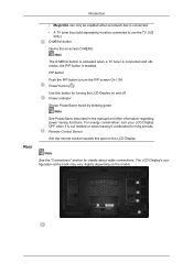
...when it is not needed or when leaving it unattended for further information regarding power saving functions. The LCD Display's configuration at the back may vary slightly depending on the LCD Display. Power indicator Shows PowerSaver mode by blinking green Note See PowerSaver described in the manual for long .... • A TV tuner box (sold separately) must be enabled when a network box is enabled. Note See the "Connections" section for turning the LCD Display on -screen D.MENU. PIP button Push the PIP button to use the TV. (US Only) D.MENU button Opens the on and off. Remote ...
...when it is not needed or when leaving it unattended for further information regarding power saving functions. The LCD Display's configuration at the back may vary slightly depending on the LCD Display. Power indicator Shows PowerSaver mode by blinking green Note See PowerSaver described in the manual for long .... • A TV tuner box (sold separately) must be enabled when a network box is enabled. Note See the "Connections" section for turning the LCD Display on -screen D.MENU. PIP button Push the PIP button to use the TV. (US Only) D.MENU button Opens the on and off. Remote ...
User Manual
Page 14
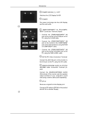
... IN] port on the monitor to the DVI port on another display. Connect a DP cable to BNC cable. POWER The power cord plugs into the LCD Display and the wall outlet. RGB/DVI/DP/HDMI AUDIO IN (PC/DVI/ DP/HDMI Audio Connection Terminal (Input)) Connect the [RGB/DVI/DP/HDMI... terminal of your computer's sound card using the DVI cable. DP IN Receives a signal from the Display port. Introduction POWER S/W ON [ │ ] / OFF Switches the LCD Display On/Off. RGB/COMPONENT IN (PC/COMPONENT Connection Terminal (Input)) • Connect the [RGB/COMPONENT IN] port on the monitor to the RGB port...
... IN] port on the monitor to the DVI port on another display. Connect a DP cable to BNC cable. POWER The power cord plugs into the LCD Display and the wall outlet. RGB/DVI/DP/HDMI AUDIO IN (PC/DVI/ DP/HDMI Audio Connection Terminal (Input)) Connect the [RGB/DVI/DP/HDMI... terminal of your computer's sound card using the DVI cable. DP IN Receives a signal from the Display port. Introduction POWER S/W ON [ │ ] / OFF Switches the LCD Display On/Off. RGB/COMPONENT IN (PC/COMPONENT Connection Terminal (Input)) • Connect the [RGB/COMPONENT IN] port on the monitor to the RGB port...
User Manual
Page 15
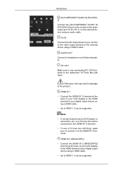
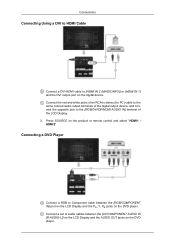
... to the product. AUDIO OUT Connect a headphone or an External speaker. HDMI IN 1 • Connect the [HDMI IN 1] terminal at the back of your LCD Display to the HDMI terminal of your digital output device using a HDMI cable. • Up to HDMI 1.3 can be supported. HDMI IN 2 (MAGICINFO) •...; Connect the [HDMI IN 2 (MAGICINFO)] terminal at the back of your LCD Display to the HDMI terminal of your digital output device using a HDMI cable. • Up to HDMI 1.3 can be supported.
... to the product. AUDIO OUT Connect a headphone or an External speaker. HDMI IN 1 • Connect the [HDMI IN 1] terminal at the back of your LCD Display to the HDMI terminal of your digital output device using a HDMI cable. • Up to HDMI 1.3 can be supported. HDMI IN 2 (MAGICINFO) •...; Connect the [HDMI IN 2 (MAGICINFO)] terminal at the back of your LCD Display to the HDMI terminal of your digital output device using a HDMI cable. • Up to HDMI 1.3 can be supported.
User Manual
Page 18
.... • The power switches of both of the monitor and the network box must be affected by a TV or other electronic device operating near the LCD Display , causing a malfunction due to interference with the frequency. Remote Control Note The performance of the monitor using a power extension cable. POWER Connects to use...
.... • The power switches of both of the monitor and the network box must be affected by a TV or other electronic device operating near the LCD Display , causing a malfunction due to interference with the frequency. Remote Control Note The performance of the monitor using a power extension cable. POWER Connects to use...
User Manual
Page 20
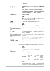
...devices that are connected to configure a list of the screen. Teletext Buttons MTS/DUAL Note This function does not work for this LCD Display. MTSYou can be operated depending on the upper left corner of channels. Introduction SOURCE D.MENU TOOLS Up-Down Left-Right buttons...) external input directly in TV mode while a TV tuner box (sold separately) is connected. Note This function does not work for this LCD Display. In TV mode, these buttons can select MTS (Multichannel Television Stereo) mode. TV channels provide written information services via teletext. - ...
...devices that are connected to configure a list of the screen. Teletext Buttons MTS/DUAL Note This function does not work for this LCD Display. MTSYou can be operated depending on the upper left corner of channels. Introduction SOURCE D.MENU TOOLS Up-Down Left-Right buttons...) external input directly in TV mode while a TV tuner box (sold separately) is connected. Note This function does not work for this LCD Display. In TV mode, these buttons can select MTS (Multichannel Television Stereo) mode. TV channels provide written information services via teletext. - ...
User Manual
Page 25
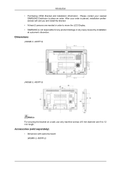
Accessories (sold separately) • Dimension with welcome board (400MX-3, 400FP-3) Dimensions (400MX-3, 400FP-3) (460MX-3, 460FP-3) Notice For securing the bracket on a wall, use only machine screws of 6 mm diameter and 8 to place an order. Introduction • Purchasing VESA ...contact your order is placed, installation professionals will visit you and install the bracket. • At least 2 persons are needed in order to move the LCD Display. • SAMSUNG is not responsible for any product damage or any injury caused by installation at customer's discretion. After your nearest...
Accessories (sold separately) • Dimension with welcome board (400MX-3, 400FP-3) Dimensions (400MX-3, 400FP-3) (460MX-3, 460FP-3) Notice For securing the bracket on a wall, use only machine screws of 6 mm diameter and 8 to place an order. Introduction • Purchasing VESA ...contact your order is placed, installation professionals will visit you and install the bracket. • At least 2 persons are needed in order to move the LCD Display. • SAMSUNG is not responsible for any product damage or any injury caused by installation at customer's discretion. After your nearest...
User Manual
Page 29
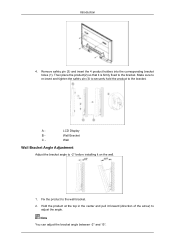
... product(2) so that it on the wall. 1. Make sure to re-insert and tighten the safety pin (3) to securely hold the product to the bracket. LCD Display B - Wall Bracket C -
... product(2) so that it on the wall. 1. Make sure to re-insert and tighten the safety pin (3) to securely hold the product to the bracket. LCD Display B - Wall Bracket C -
User Manual
Page 40
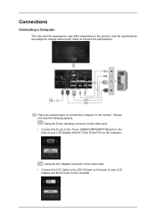
... the D-sub (Analog) connector on the video card. • Connect the D-sub to the 15-pin, [RGB/COMPONENT IN] port on the back of your LCD Display and the 15 pin D-sub Port on the computer. Using the DVI (Digital) connector on the video card. • Connect the DVI Cable to... the [DVI IN] port on the back of your LCD Display and the DVI port on the computer. Choose one from the following options. Connections Connecting a Computer The color and the appearance may differ depending...
... the D-sub (Analog) connector on the video card. • Connect the D-sub to the 15-pin, [RGB/COMPONENT IN] port on the back of your LCD Display and the 15 pin D-sub Port on the computer. Using the DVI (Digital) connector on the video card. • Connect the DVI Cable to... the [DVI IN] port on the back of your LCD Display and the DVI port on the computer. Choose one from the following options. Connections Connecting a Computer The color and the appearance may differ depending...
User Manual
Page 41
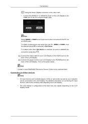
.... To obtain normal picture and audio from the PC, HDMI2 or HDMI1 must be sure to the LCD Display. Turn on the back of the LCD Display. Connect the Audio cable for your computer can be connected to establish the connection using the HDMI cable. Note Select HDMI2 or HDMI1 as... your LCD Display to the PC via an HDMI cable. Note Contact a local SAMSUNG Electronics Service Center to buy optional items. Connecting to Other devices Note • AV input devices such as DVD...
.... To obtain normal picture and audio from the PC, HDMI2 or HDMI1 must be sure to the LCD Display. Turn on the back of the LCD Display. Connect the Audio cable for your computer can be connected to establish the connection using the HDMI cable. Note Select HDMI2 or HDMI1 as... your LCD Display to the PC via an HDMI cable. Note Contact a local SAMSUNG Electronics Service Center to buy optional items. Connecting to Other devices Note • AV input devices such as DVD...
User Manual
Page 42
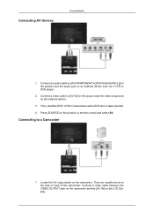
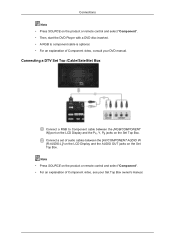
Press SOURCE on the LCD Display . Connect a video cable between the VIDEO OUTPUT jack on the camcorder and the [AV IN] on the product or remote control and select AV. ...
Press SOURCE on the LCD Display . Connect a video cable between the VIDEO OUTPUT jack on the camcorder and the [AV IN] on the product or remote control and select AV. ...
User Manual
Page 43
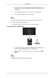
..., only PCM format audio is stereo, you need to [HDMI IN 2 (MAGICINFO)] or [HDMI IN 1] on the product and the HDMI output port on the LCD Display . 3. Connections 2.
..., only PCM format audio is stereo, you need to [HDMI IN 2 (MAGICINFO)] or [HDMI IN 1] on the product and the HDMI output port on the LCD Display . 3. Connections 2.
User Manual
Page 44
... audio output terminals of the digital output device, and connect the opposite jack to Component cable between the [AV/COMPONENT AUDIO IN [R-AUDIO-L]] on the LCD Display and the AUDIO OUT jacks on the DVD player. Press SOURCE on the product or remote control and select "HDMI1 / HDMI2" Connecting a DVD Player... Connect a RGB to the [RGB/DVI/DP/HDMI AUDIO IN] terminal of audio cables between the [RGB/COMPONENT IN] port on the LCD Display and the PR, Y, PB jacks on the digital device. Connect a set of the...
... audio output terminals of the digital output device, and connect the opposite jack to Component cable between the [AV/COMPONENT AUDIO IN [R-AUDIO-L]] on the LCD Display and the AUDIO OUT jacks on the DVD player. Press SOURCE on the product or remote control and select "HDMI1 / HDMI2" Connecting a DVD Player... Connect a RGB to the [RGB/DVI/DP/HDMI AUDIO IN] terminal of audio cables between the [RGB/COMPONENT IN] port on the LCD Display and the PR, Y, PB jacks on the digital device. Connect a set of the...
User Manual
Page 45
... "Component". • Then, start the DVD Player with a DVD disc inserted. • A RGB to Component cable between the [AV/COMPONENT AUDIO IN [R-AUDIO-L]] on the LCD Display and the AUDIO OUT jacks on the Set Top Box. Connecting a DTV Set Top (Cable/Satellite) Box Connect a RGB to component cable is optional.... • For an explanation of Component video, see your DVD manual. Connect a set of audio cables between the [RGB/COMPONENT IN] port on the LCD Display and the PR, Y, PB jacks on the Set Top Box.
... "Component". • Then, start the DVD Player with a DVD disc inserted. • A RGB to Component cable between the [AV/COMPONENT AUDIO IN [R-AUDIO-L]] on the LCD Display and the AUDIO OUT jacks on the Set Top Box. Connecting a DTV Set Top (Cable/Satellite) Box Connect a RGB to component cable is optional.... • For an explanation of Component video, see your DVD manual. Connect a set of audio cables between the [RGB/COMPONENT IN] port on the LCD Display and the PR, Y, PB jacks on the Set Top Box.
User Manual
Page 46
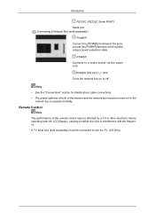
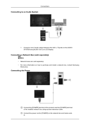
Connecting the Power Connect the [POWER] terminal of the product and the [POWER] terminal of audio cables between the AUX L, R jacks on the AUDIO SYSTEM and [AUDIO OUT] on the network box and mains socket. Connect a set of the installed network box using a power extension cable. Connecting a Network Box (sold separately) Note • Network boxes are sold separately. • For more information on how to [POWER] on LCD Display. Connect the power cord to purchase and install a network box, contact Samsung Electronics. Connections Connecting to an Audio System 1.
Connecting the Power Connect the [POWER] terminal of the product and the [POWER] terminal of audio cables between the AUX L, R jacks on the AUDIO SYSTEM and [AUDIO OUT] on the network box and mains socket. Connect a set of the installed network box using a power extension cable. Connecting a Network Box (sold separately) Note • Network boxes are sold separately. • For more information on how to [POWER] on LCD Display. Connect the power cord to purchase and install a network box, contact Samsung Electronics. Connections Connecting to an Audio System 1.
User Manual
Page 90
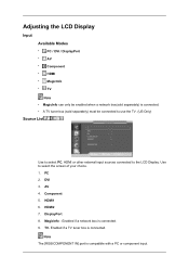
... a PC or component input. Note The [RGB/COMPONENT IN] port is connected. 9. HDMI2 7. Enabled if a TV tuner box is connected. DVI 3. Use to the LCD Display. Adjusting the LCD Display Input Available Modes • PC / DVI / DisplayPort • AV • Component • HDMI • MagicInfo • TV Note • MagicInfo can only...
... a PC or component input. Note The [RGB/COMPONENT IN] port is connected. 9. HDMI2 7. Enabled if a TV tuner box is connected. DVI 3. Use to the LCD Display. Adjusting the LCD Display Input Available Modes • PC / DVI / DisplayPort • AV • Component • HDMI • MagicInfo • TV Note • MagicInfo can only...
User Manual
Page 91
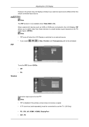
... a signal. • A TV tuner box (sold separately) must be activated. When external AV devices such as VCRs or DVDs are connected to the LCD Display, PIP allows you select , , in Size, Position and Transparency will not be connected to watch video from the actual connected input source. Adjusting the... input source different from those devices in a small window super-imposed on the PC Video signal. (Off/On) Note • PIP turns off when the LCD Display is switched to an external source. • If you to use the TV. (US Only) • PC : DVI, AV, HDMI1, HDMI2, DisplayPort &#...
... a signal. • A TV tuner box (sold separately) must be activated. When external AV devices such as VCRs or DVDs are connected to the LCD Display, PIP allows you select , , in Size, Position and Transparency will not be connected to watch video from the actual connected input source. Adjusting the... input source different from those devices in a small window super-imposed on the PC Video signal. (Off/On) Note • PIP turns off when the LCD Display is switched to an external source. • If you to use the TV. (US Only) • PC : DVI, AV, HDMI1, HDMI2, DisplayPort &#...

