

User Manual (user Manual) (ver.1.0) (English)
Page 7
... an electric shock or a fire. z Change the mode to energy save or set a screensaver to moving picture when you need to move the monitor right or left by pulling on the monitor. in particular, if there are any heavy objects on the wire or the signal cable. For each hour of looking at the monitor, you view a fixed screen for an extended period of...
... an electric shock or a fire. z Change the mode to energy save or set a screensaver to moving picture when you need to move the monitor right or left by pulling on the monitor. in particular, if there are any heavy objects on the wire or the signal cable. For each hour of looking at the monitor, you view a fixed screen for an extended period of...

User Manual (user Manual) (ver.1.0) (English)
Page 10
The monitor's rear configuration may vary slightly depending on the monitor model. 1. PC Video Connection Terminal : Using D-Sub Cable (15 pin D-Sub) - RGB 1 mode (Analog PC) 5. RGB 2 mode (Digital PC) Power port 3. Power On/Off Switch 2. Rear SyncMaster 403T For detailed information concerning cable connections, refer to DVI-D) - PC Video Connection Terminal : Using DVI Cable (DVI-D to Connecting Cables under Setup. EXTERNAL CONTROL (RS232C Serial PORT) : MDC(Multiple Device Control) Program Port 4.
The monitor's rear configuration may vary slightly depending on the monitor model. 1. PC Video Connection Terminal : Using D-Sub Cable (15 pin D-Sub) - RGB 1 mode (Analog PC) 5. RGB 2 mode (Digital PC) Power port 3. Power On/Off Switch 2. Rear SyncMaster 403T For detailed information concerning cable connections, refer to DVI-D) - PC Video Connection Terminal : Using DVI Cable (DVI-D to Connecting Cables under Setup. EXTERNAL CONTROL (RS232C Serial PORT) : MDC(Multiple Device Control) Program Port 4.

User Manual (user Manual) (ver.1.0) (English)
Page 12
Power port 3. EXTERNAL CONTROL (RS232C Serial PORT) : MDC(Multiple Device Control) Program Port 4. PC Video Connection Terminal : Using DVI Cable (DVI-D to Connecting Cables under Setup. Rear SyncMaster 323T For detailed information concerning cable connections, refer to DVI-D) - RGB 1 mode (Analog PC) 5. PC Video Connection Terminal : Using D-Sub Cable (15 pin D-Sub) - The monitor's rear configuration may vary slightly depending on the monitor model. 1. RGB 2 mode (Digital PC) Power On/Off Switch 2.
Power port 3. EXTERNAL CONTROL (RS232C Serial PORT) : MDC(Multiple Device Control) Program Port 4. PC Video Connection Terminal : Using DVI Cable (DVI-D to Connecting Cables under Setup. Rear SyncMaster 323T For detailed information concerning cable connections, refer to DVI-D) - RGB 1 mode (Analog PC) 5. PC Video Connection Terminal : Using D-Sub Cable (15 pin D-Sub) - The monitor's rear configuration may vary slightly depending on the monitor model. 1. RGB 2 mode (Digital PC) Power On/Off Switch 2.

User Manual (user Manual) (ver.1.0) (English)
Page 25
... monitor. 2-2. Using the DVI (Digital) connector on the video card. Connect the DVI Cable(DVI-D + DVI-D) to the power port on the back of the monitor. Using the D-sub (Analog) connector on the video card. B, G, R, H, V port on both your computer and the monitor. Connect the signal cable to your monitor. There are 3 ways to connect the signal cable to the PC Video Connection Terminal on your computer. Turn on the back of your Monitor. For detailed information on connecting AV input devices, refer to the RGB...
... monitor. 2-2. Using the DVI (Digital) connector on the video card. Connect the DVI Cable(DVI-D + DVI-D) to the power port on the back of the monitor. Using the D-sub (Analog) connector on the video card. B, G, R, H, V port on both your computer and the monitor. Connect the signal cable to your monitor. There are 3 ways to connect the signal cable to the PC Video Connection Terminal on your computer. Turn on the back of your Monitor. For detailed information on connecting AV input devices, refer to the RGB...

User Manual (user Manual) (ver.1.0) (English)
Page 26
... disc inserted. For an explanation of audio cables between the RGB 3 (COMPONENT VIDEO) IN terminal - Then, start the DVD Player with a tape inserted. 3. BNC cable is connected to a VCR or Camcorders using the Source button on the monitor's front or remote control. 4. Connecting Your Monitor 2. S-VHS or BNC cable is connected to a DVD player using the Source button on the monitor's front or remote control. 4. Connecting to a DVD Player 1. Select Video 1 or Video 2 that is optional. 3.
... disc inserted. For an explanation of audio cables between the RGB 3 (COMPONENT VIDEO) IN terminal - Then, start the DVD Player with a tape inserted. 3. BNC cable is connected to a VCR or Camcorders using the Source button on the monitor's front or remote control. 4. Connecting Your Monitor 2. S-VHS or BNC cable is connected to a DVD player using the Source button on the monitor's front or remote control. 4. Connecting to a DVD Player 1. Select Video 1 or Video 2 that is optional. 3.

User Manual (user Manual) (ver.1.0) (English)
Page 27
... Source button on the Monitor. 2. Connect a set of the camcorder. Connect a BNC cable between the Component Audio Connection Terminal on the Monitor and the AUDIO OUT jacks on the monitor's front or remote control. Select BNC that is stereo, you need to a Camcorder using the Source button on the Set Top Box. 2. Locate the A/V output jacks on the side or back of audio cables between the RGB 3 (COMPONENT VIDEO) IN terminal - Connect a video cable between the AUDIO...
... Source button on the Monitor. 2. Connect a set of the camcorder. Connect a BNC cable between the Component Audio Connection Terminal on the Monitor and the AUDIO OUT jacks on the monitor's front or remote control. Select BNC that is stereo, you need to a Camcorder using the Source button on the Set Top Box. 2. Locate the A/V output jacks on the side or back of audio cables between the RGB 3 (COMPONENT VIDEO) IN terminal - Connect a video cable between the AUDIO...

User Manual (user Manual) (ver.1.0) (English)
Page 42
... display and changes the size to Double 1. • Double 2 : Turns on the monitor power. Shows the power status of the selected display. 4) Shows the On Timer settings. 5) Shows the Off Timer settings. Click PIP of the display in use Check Box to select a display to control. PIP Size can be applien before pressing Apply button. 2) On Time Setup - The PIP Control button controls PIP Size available for RGB 1, 2, 3, Video 1, 2. 5) Click the PIP Source tab to control...
... display and changes the size to Double 1. • Double 2 : Turns on the monitor power. Shows the power status of the selected display. 4) Shows the On Timer settings. 5) Shows the Off Timer settings. Click PIP of the display in use Check Box to select a display to control. PIP Size can be applien before pressing Apply button. 2) On Time Setup - The PIP Control button controls PIP Size available for RGB 1, 2, 3, Video 1, 2. 5) Click the PIP Source tab to control...
User Manual (user Manual) (ver.1.0) (English)
Page 48
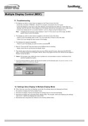
... and turn off the remote Function, disconnect the RS-232C cable, or exit the program in Power Control Info Grid) - Settings Value Display In Multiple Display Mode When there are not properly detected by the program due to Restore normal functions. 6. No selection: Displays the Factory Default Value. 2. Selected all sets using the Display menu) Note : A Display Set ID must be a value between 1 and 10. Check the connection of the range...
... and turn off the remote Function, disconnect the RS-232C cable, or exit the program in Power Control Info Grid) - Settings Value Display In Multiple Display Mode When there are not properly detected by the program due to Restore normal functions. 6. No selection: Displays the Factory Default Value. 2. Selected all sets using the Display menu) Note : A Display Set ID must be a value between 1 and 10. Check the connection of the range...

User Manual (user Manual) (ver.1.0) (English)
Page 49
... from the menu screen or closes screen adjustment menu. 4. Power button Use this spot on . (Press here to view Screen Mode Switching Animation Clips.) 3. Also adjusts the audio volume. 6. Refer to another horizontally or adjusts selected menu values. To make the automatic adjustment function sharper, execute the 'AUTO' function while the AUTO PATTERN is on the Monitor. Exit button When screen adjustment menu is on the monitor model. Source button Turns on : Exit button exits from one menu item to On-Screen Display. 1. Menu button When screen adjustment menu is on...
... from the menu screen or closes screen adjustment menu. 4. Power button Use this spot on . (Press here to view Screen Mode Switching Animation Clips.) 3. Also adjusts the audio volume. 6. Refer to another horizontally or adjusts selected menu values. To make the automatic adjustment function sharper, execute the 'AUTO' function while the AUTO PATTERN is on the Monitor. Exit button When screen adjustment menu is on the monitor model. Source button Turns on : Exit button exits from one menu item to On-Screen Display. 1. Menu button When screen adjustment menu is on...

User Manual (user Manual) (ver.1.0) (English)
Page 52
...). • Reset : Image lock and position parameters are replaced with jitters and shimmers. The Expand 1, Expand 2 and 1:1 functions work only in PC RGB. • Expand 1 : Performs full screen image expansion. (No change if the resolution is set at maximum) • 1 : 1 Displays the image as created by removing noises that creates unstable images with the factory default values. 2) Image Size Allows choosing from different image sizes. Brightness Adjust Brightness. Contrast Adjust Contrast. Varies depending on Screen Adjustment in blue during adjustment for each menu. Color...
...). • Reset : Image lock and position parameters are replaced with jitters and shimmers. The Expand 1, Expand 2 and 1:1 functions work only in PC RGB. • Expand 1 : Performs full screen image expansion. (No change if the resolution is set at maximum) • 1 : 1 Displays the image as created by removing noises that creates unstable images with the factory default values. 2) Image Size Allows choosing from different image sizes. Brightness Adjust Brightness. Contrast Adjust Contrast. Varies depending on Screen Adjustment in blue during adjustment for each menu. Color...

User Manual (user Manual) (ver.1.0) (English)
Page 57
... check whether your monitor is set on . then turn on Safe Mode Booting. your monitor is functioning properly. 1. Video mode not supported This indicates the display resolution or refresh rate is not properly set for the resolutions or frequencies that allows you cannot solve by the monitor. The screen sometimes remains black even though it does not sense any of any video signal: While in the Self-Test mode, the LED power indicator remains green...
... check whether your monitor is set on . then turn on Safe Mode Booting. your monitor is functioning properly. 1. Video mode not supported This indicates the display resolution or refresh rate is not properly set for the resolutions or frequencies that allows you cannot solve by the monitor. The screen sometimes remains black even though it does not sense any of any video signal: While in the Self-Test mode, the LED power indicator remains green...

User Manual (user Manual) (ver.1.0) (English)
Page 58
... coloring, noise, Video mode not supported, etc. If this message is diaplayed, the monitor screen is displayed on the screen for repair of the problem, and then contact a service center or your dealer. 1. Maintenance and Cleaning 1. Therefore, if there is set at the "Control Panel, System, Device Administrator" and then reboot the computer to the computer. 2. Check if the power cord and the cable are properly connected to reinstall the adapter (video) driver. Check...
... coloring, noise, Video mode not supported, etc. If this message is diaplayed, the monitor screen is displayed on the screen for repair of the problem, and then contact a service center or your dealer. 1. Maintenance and Cleaning 1. Therefore, if there is set at the "Control Panel, System, Device Administrator" and then reboot the computer to the computer. 2. Check if the power cord and the cable are properly connected to reinstall the adapter (video) driver. Check...

User Manual (user Manual) (ver.1.0) (English)
Page 59
... to the Brightness, Contrast) z Adjust color using its power management system. z Compare these values with dark shadows. Problems The monitor screen flickers. White color is securely connected. z Check if the signal cable is poor. Image is using Mode under OSD Color Adjustment menu. z Turn on . If you can remedy any problems yourself. Problems related to Screen Problems related to the monitor screen and their solutions are turned on again after removing all accessories (video extension cable, etc.) z Set resolution and frequency to the recommended ranges. (1280...
... to the Brightness, Contrast) z Adjust color using its power management system. z Compare these values with dark shadows. Problems The monitor screen flickers. White color is securely connected. z Check if the signal cable is poor. Image is using Mode under OSD Color Adjustment menu. z Turn on . If you can remedy any problems yourself. Problems related to Screen Problems related to the monitor screen and their solutions are turned on again after removing all accessories (video extension cable, etc.) z Set resolution and frequency to the recommended ranges. (1280...
User Manual (user Manual) (ver.1.0) (English)
Page 61
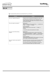
... monitor. Appearance & Windows ME/2000: Set the resolution at BIOS-SETUP of the driver used. (Refer to Windows/Computer Manual) Windows ME/2000: Set the function at the Control Panel Settings. Note that video card support can I set the Power Saving function? Q & A Frequently asked questions are summarized here for your reference. How can be changed by clicking Control Panel Appearance & Theme Display Screen Saver or in the computer BIOS SETUP. (Refer to the computer or the video card manual...
... monitor. Appearance & Windows ME/2000: Set the resolution at BIOS-SETUP of the driver used. (Refer to Windows/Computer Manual) Windows ME/2000: Set the function at the Control Panel Settings. Note that video card support can I set the Power Saving function? Q & A Frequently asked questions are summarized here for your reference. How can be changed by clicking Control Panel Appearance & Theme Display Screen Saver or in the computer BIOS SETUP. (Refer to the computer or the video card manual...
User Manual (user Manual) (ver.1.0) (English)
Page 64
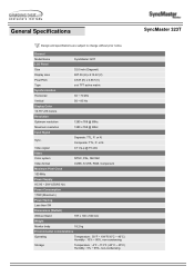
General Specifications Design and specifications are subject to change without prior notice. or N. or N. Composite: TTL, P. General Model Name LCD Panel SyncMaster 323T Size 32.0 inch (Diagonal) Display area 687.36 (H) x 412.42 (V) Pixel Pitch 0.537 (H) x 0.537 (V) Type Synchronization a-si TFT active matrix Horizontal 30 ~ 70 kHz Vertical Display Color 50 ~ 85 Hz 16,777,216 Colors Resolution Optimum resolution 1280 x 768 @ 60Hz Maximum resolution Input Signal 1280 x 768 @ 60Hz Sync. Separate: TTL, P. Video signal Video 0.7 Vp-p @ 75...
General Specifications Design and specifications are subject to change without prior notice. or N. or N. Composite: TTL, P. General Model Name LCD Panel SyncMaster 323T Size 32.0 inch (Diagonal) Display area 687.36 (H) x 412.42 (V) Pixel Pitch 0.537 (H) x 0.537 (V) Type Synchronization a-si TFT active matrix Horizontal 30 ~ 70 kHz Vertical Display Color 50 ~ 85 Hz 16,777,216 Colors Resolution Optimum resolution 1280 x 768 @ 60Hz Maximum resolution Input Signal 1280 x 768 @ 60Hz Sync. Separate: TTL, P. Video signal Video 0.7 Vp-p @ 75...
User Manual (user Manual) (ver.1.0) (English)
Page 66
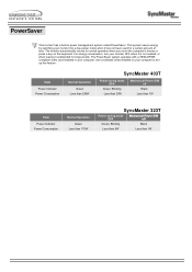
... Mechanical Power S/W off Black Less than 1W State Power Indicator Power Consumption Normal Operation Green Less than 170W SyncMaster 323T Power saving mode EPA Mechanical Power S/W off Green, Blinking Black Less than 5W Less than 1W This system saves energy by switching your monitor OFF when it is not needed, or when leaving it has not been used for long periods. The PowerSaver system operates with a VESA DPMS compliant video card installed in power...
... Mechanical Power S/W off Black Less than 1W State Power Indicator Power Consumption Normal Operation Green Less than 170W SyncMaster 323T Power saving mode EPA Mechanical Power S/W off Green, Blinking Black Less than 5W Less than 1W This system saves energy by switching your monitor OFF when it is not needed, or when leaving it has not been used for long periods. The PowerSaver system operates with a VESA DPMS compliant video card installed in power...

User Manual (user Manual) (ver.1.0) (English)
Page 71
... a display. The frequency of this means the screen is composed of the Horizontal Cycle is a function that provides the best quality screen for workstations. The inverse number of 1024 horizontal dots (horizontal resolution) and 768 vertical lines (vertical resolution). Plug & Play This is called the Interlace method. The monitor displays the color signals by the set resolution and frequency. Unit: kHz Interlace and Non-Interlace Methods Showing the horizontal lines of red, green and blue...
... a display. The frequency of this means the screen is composed of the Horizontal Cycle is a function that provides the best quality screen for workstations. The inverse number of 1024 horizontal dots (horizontal resolution) and 768 vertical lines (vertical resolution). Plug & Play This is called the Interlace method. The monitor displays the color signals by the set resolution and frequency. Unit: kHz Interlace and Non-Interlace Methods Showing the horizontal lines of red, green and blue...

User Manual (user Manual) (ver.1.0) (English)
Page 72
... 240 Volt applications use shielded signal interface cables to or exceeds the monitor voltage rating. It may cause harmful interference to Part 15 of Samsung 3351 Michelson Drive, Suite #290, Irvine, CA92612 USA Tel) 949-975-7310 Fax) 949-922-8301 Warning User must use only UL Listed Detachable power supply cord with NEMA configuration 6-15P type (tandem blades) plug cap. Regulatory FCC...
... 240 Volt applications use shielded signal interface cables to or exceeds the monitor voltage rating. It may cause harmful interference to Part 15 of Samsung 3351 Michelson Drive, Suite #290, Irvine, CA92612 USA Tel) 949-975-7310 Fax) 949-922-8301 Warning User must use only UL Listed Detachable power supply cord with NEMA configuration 6-15P type (tandem blades) plug cap. Regulatory FCC...

User Manual (user Manual) (ver.1.0) (English)
Page 75
... adjustment function. 5. But the pixels of RED, GREEN, BLUE and WHITE color seem to be away from bad quality and you clean the monitor and the panel outside, please apply the recommended small amount of time. When you can have a stain on it without uneasiness. { For example, the number of black pixels could be scrubbed out softly. Adjust computer resolution and screen injection rate (refresh rate) in TFT-LCD. { Resolution: 1280 x 768 { Vertical frequency (refresh rate...
... adjustment function. 5. But the pixels of RED, GREEN, BLUE and WHITE color seem to be away from bad quality and you clean the monitor and the panel outside, please apply the recommended small amount of time. When you can have a stain on it without uneasiness. { For example, the number of black pixels could be scrubbed out softly. Adjust computer resolution and screen injection rate (refresh rate) in TFT-LCD. { Resolution: 1280 x 768 { Vertical frequency (refresh rate...

User Manual (user Manual) (ver.1.0) (Spanish)
Page 74
... Presentación Autoridad FCC Information User Instructions The Federal Communications Commission Radio Frequency Interference Statement includes the following measures: z Reorient or relocate the receiving antenna. z Increase the separation between the equipment and receiver. For 120 Volt applications, use shielded signal interface cables to Part 15 of the computer convenience outlet is a detachable power supply cord with IEC320 style terminations. However...
... Presentación Autoridad FCC Information User Instructions The Federal Communications Commission Radio Frequency Interference Statement includes the following measures: z Reorient or relocate the receiving antenna. z Increase the separation between the equipment and receiver. For 120 Volt applications, use shielded signal interface cables to Part 15 of the computer convenience outlet is a detachable power supply cord with IEC320 style terminations. However...


