

User Manual (ENGLISH)
Page 3
... On Screen Display (OSD 11 Accessing the Menu System 11 OSD functions and adjustment 12 By Remote-Control 19 Appendix 20 Power Saver 20 Troubleshooting 21 Specifications 23 Pin Assignments 24 Display Modes 25 Changing the Base 26 Removing the base 26 Attaching a base 27 Maintenance of Your LCD...
... On Screen Display (OSD 11 Accessing the Menu System 11 OSD functions and adjustment 12 By Remote-Control 19 Appendix 20 Power Saver 20 Troubleshooting 21 Specifications 23 Pin Assignments 24 Display Modes 25 Changing the Base 26 Removing the base 26 Attaching a base 27 Maintenance of Your LCD...

User Manual (ENGLISH)
Page 9
Monitor self-test screen * It shows signal source is not connected with a large blue oval Samsung logo and an error messsage "CHECK SIGNAL CABLE." Getting Help If your monitor does not display an image, check... adjustments for parameters, allow the LCD monitor to warm (be turned off both your cable connections and refer to "Troubleshooting" on page 21. If your monitor screen remains blank after letting the monitor be on) for a couple of the displayed image, run Auto Adjustment by... Digital, Video or S-Video. If you will see a white box with one of the computer. 3 Turn on page 21.
Monitor self-test screen * It shows signal source is not connected with a large blue oval Samsung logo and an error messsage "CHECK SIGNAL CABLE." Getting Help If your monitor does not display an image, check... adjustments for parameters, allow the LCD monitor to warm (be turned off both your cable connections and refer to "Troubleshooting" on page 21. If your monitor screen remains blank after letting the monitor be on) for a couple of the displayed image, run Auto Adjustment by... Digital, Video or S-Video. If you will see a white box with one of the computer. 3 Turn on page 21.
User Manual (ENGLISH)
Page 10
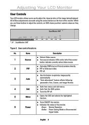
.... English 8 Adjusting Your LCD Monitor User Controls Your LCD monitor allows you their numeric values as they change. * SOURCE PIP AUTO EXIT VIDEO PC MENU * 21" : SyncMaster 210T Figure 6.
.... English 8 Adjusting Your LCD Monitor User Controls Your LCD monitor allows you their numeric values as they change. * SOURCE PIP AUTO EXIT VIDEO PC MENU * 21" : SyncMaster 210T Figure 6.

User Manual (ENGLISH)
Page 23
... are turned on . n Compare these values with the data in the Display Modes Timing Chart. Image Lock, Fine, page 12. Image What you see... English 21 Before contacting customer service, try the suggested actions that the PC or video sources are appropriate to your LCD power indicator is off connected and...
... are turned on . n Compare these values with the data in the Display Modes Timing Chart. Image Lock, Fine, page 12. Image What you see... English 21 Before contacting customer service, try the suggested actions that the PC or video sources are appropriate to your LCD power indicator is off connected and...

User Manual (ENGLISH)
Page 25
... Deutsch Français English Appendix Specifications Table 4. or N. English 23 Technical and environmental specifications Panel * Frequency 210T Size Display Size Type Pixel pitch Viewing Angle 21.3" Diagonal 432 (H) x 324 (V) mm a-si TFT Active matrix 0.27 (H) x 0.27 (V) mm 80˚/80˚/80˚/80˚ Horizontal Vertical...
... Deutsch Français English Appendix Specifications Table 4. or N. English 23 Technical and environmental specifications Panel * Frequency 210T Size Display Size Type Pixel pitch Viewing Angle 21.3" Diagonal 432 (H) x 324 (V) mm a-si TFT Active matrix 0.27 (H) x 0.27 (V) mm 80˚/80˚/80˚/80˚ Horizontal Vertical...

User Manual (ENGLISH)
Page 26
... Assigneut 13 No Connect 14 15V Power 15 Ground (for 15V) 16 Hot Plug Detect 17 T.M.D.S Data 0- 18 T.M.D.S Data 0+ 19 T.M.D.S Data 0 Shield 20 No Connect 21 No Connect 22 T.M.D.S Clock Shield 23 T.M.D.S Clock + 24 T.M.D.S Clock - English 24 Appendix Pin Assignments Table 5. 15 pin D-sub connector Pin Separate H/V 1 Red 2 Green 3 Blue 4 GND...
... Assigneut 13 No Connect 14 15V Power 15 Ground (for 15V) 16 Hot Plug Detect 17 T.M.D.S Data 0- 18 T.M.D.S Data 0+ 19 T.M.D.S Data 0 Shield 20 No Connect 21 No Connect 22 T.M.D.S Clock Shield 23 T.M.D.S Clock + 24 T.M.D.S Clock - English 24 Appendix Pin Assignments Table 5. 15 pin D-sub connector Pin Separate H/V 1 Red 2 Green 3 Blue 4 GND...

User Manual (ENGLISH)
Page 30
... 8 Power Indicator 6 Power Saver 20 R Remote Controller 3 Recall 14 S Safety Instructions 2 Self-Test Feature Check 6 Size 16 Source 8, 9 Speaker 3 S-VHS Cable 3 T Tilt the screen 4 Troubleshooting 21 U User control locations 8 V Video control 18 V-pan 15 V-position 13 W Warranty card 3 Z Zoom 15 English 28
... 8 Power Indicator 6 Power Saver 20 R Remote Controller 3 Recall 14 S Safety Instructions 2 Self-Test Feature Check 6 Size 16 Source 8, 9 Speaker 3 S-VHS Cable 3 T Tilt the screen 4 Troubleshooting 21 U User control locations 8 V Video control 18 V-pan 15 V-position 13 W Warranty card 3 Z Zoom 15 English 28
