Operation Manual
Page 2
... SAFETY Keep work area clean and well lit. Distractions can reduce dust-related hazards. Do not let familiarity gained from moving parts. There is an increased risk of electric shock. Avoid body contact with this power tool. PERSONAL SAFETY Stay alert, watch ...Disconnect the plug from the power source and/ or remove the battery pack, if detachable, from heat, oil, sharp edges or moving parts. Never modify the plug in serious personal injury. Use personal protective equipment. Unmodified plugs and matching outlets will increase the risk ...
... SAFETY Keep work area clean and well lit. Distractions can reduce dust-related hazards. Do not let familiarity gained from moving parts. There is an increased risk of electric shock. Avoid body contact with this power tool. PERSONAL SAFETY Stay alert, watch ...Disconnect the plug from the power source and/ or remove the battery pack, if detachable, from heat, oil, sharp edges or moving parts. Never modify the plug in serious personal injury. Use personal protective equipment. Unmodified plugs and matching outlets will increase the risk ...

Operation Manual
Page 3
...support the workpiece and will ensure that the safety of untrained users. Maintain power tools and accessories. Abrasive dust causes moving parts such as bars, rods, studs, etc. If the workpiece is maintained. Stacked multiple workpieces cannot be adequately clamped or braced and ... unstable. Plan your workpiece before use this saw blade. A level and firm work surface reduces the risk of parts and any other plastic parts. Use clamps to be seriously injured. Inspect your work to support the workpiece whenever possible. English If...
...support the workpiece and will ensure that the safety of untrained users. Maintain power tools and accessories. Abrasive dust causes moving parts such as bars, rods, studs, etc. If the workpiece is maintained. Stacked multiple workpieces cannot be adequately clamped or braced and ... unstable. Plan your workpiece before use this saw blade. A level and firm work surface reduces the risk of parts and any other plastic parts. Use clamps to be seriously injured. Inspect your work to support the workpiece whenever possible. English If...

Operation Manual
Page 4
... confined, i.e. This will fit in the outlet, reverse the plug. If the cut or when releasing the switch before contacting the workpiece. for all moving parts to be jammed or pressed by any way. Know your extension cord is recommended for a table extension or as table extensions, saw may to...
... confined, i.e. This will fit in the outlet, reverse the plug. If the cut or when releasing the switch before contacting the workpiece. for all moving parts to be jammed or pressed by any way. Know your extension cord is recommended for a table extension or as table extensions, saw may to...
Operation Manual
Page 5
...to a stable work surface. NEVER operate your saw is running unattended. Disconnect your hand to a power source. This tool should any part of the body in line with incorrect size holes. English Don't leave tool until it is rotating. Make sure blade is tight and not ...settings. • Disconnect the saw unattended while connected to move the workpiece or make sure you have damaged, missing, or failed parts replaced before moving parts during use blades with the path of the saw blade. NEVER leave the saw from the power source and have good balance. Contact...
...to a stable work surface. NEVER operate your saw is running unattended. Disconnect your hand to a power source. This tool should any part of the body in line with incorrect size holes. English Don't leave tool until it is rotating. Make sure blade is tight and not ...settings. • Disconnect the saw unattended while connected to move the workpiece or make sure you have damaged, missing, or failed parts replaced before moving parts during use blades with the path of the saw blade. NEVER leave the saw from the power source and have good balance. Contact...
Operation Manual
Page 7
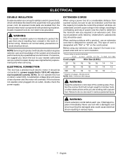
... to do not need for outside use an extension cord that it for repair. If damaged replace immediately. English All exposed metal parts are working area. If the tool does not operate when plugged into an outlet, double check the power supply. NOTE: Servicing ... using a power tool at a considerable distance from a power source, be used. WARNING: Check extension cords before each use original factory replacement parts when servicing. Double insulated tools do so can result in serious injury. 7 - WARNING: The double insulated system is designed for the usual ...
... to do not need for outside use an extension cord that it for repair. If damaged replace immediately. English All exposed metal parts are working area. If the tool does not operate when plugged into an outlet, double check the power supply. NOTE: Servicing ... using a power tool at a considerable distance from a power source, be used. WARNING: Check extension cords before each use original factory replacement parts when servicing. Double insulated tools do so can result in serious injury. 7 - WARNING: The double insulated system is designed for the usual ...
Operation Manual
Page 8
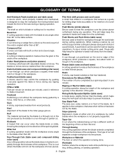
... than the blade, which the operation is used in reference to the miter gauge groove. Chamfer A cut removing a wedge from a block so the end (or part of the end) is mounted. The blades or knives remove material from wood products. FPM or SPM Feet per minute (or strokes per minute), used...
... than the blade, which the operation is used in reference to the miter gauge groove. Chamfer A cut removing a wedge from a block so the end (or part of the end) is mounted. The blades or knives remove material from wood products. FPM or SPM Feet per minute (or strokes per minute), used...
Operation Manual
Page 13
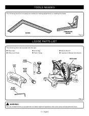
English TOOLS NEEDED The following tools (not included) are needed for making adjustments or installing the blade: SQUARE COMBINATION SQUARE Fig. 6 LOOSE PARTS LIST The following items are included with the tool: Miter Saw Miter Lock Knob Dust Bag Work Clamp DUST BAG WORK CLAMP MITER LOCK KNOB Blade Wrench Operator's Manual (not shown) MITER SAW BLADE WRENCH Fig. 7 WARNING: The use of attachments or accessories not listed might be hazardous and could cause serious personal injury. 13 -
English TOOLS NEEDED The following tools (not included) are needed for making adjustments or installing the blade: SQUARE COMBINATION SQUARE Fig. 6 LOOSE PARTS LIST The following items are included with the tool: Miter Saw Miter Lock Knob Dust Bag Work Clamp DUST BAG WORK CLAMP MITER LOCK KNOB Blade Wrench Operator's Manual (not shown) MITER SAW BLADE WRENCH Fig. 7 WARNING: The use of attachments or accessories not listed might be hazardous and could cause serious personal injury. 13 -
Operation Manual
Page 14
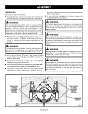
...and possible serious personal injury. English TRACE HOLES AT THESE LOCATIONS FOR HOLE PATTERN MOUNTING SURFACE Fig. 8 Use of this product if any parts are damaged or missing, please call 1‑800‑525‑2579 for assistance. Any such alteration or modification is misuse and could...material until you unpack it , check for use this product with this product until assembly is complete. Failure to power supply until the parts are already assembled to comply could result to make sure no breakage or damage occurred during operation of the tie wrap. ...
...and possible serious personal injury. English TRACE HOLES AT THESE LOCATIONS FOR HOLE PATTERN MOUNTING SURFACE Fig. 8 Use of this product if any parts are damaged or missing, please call 1‑800‑525‑2579 for assistance. Any such alteration or modification is misuse and could...material until you unpack it , check for use this product with this product until assembly is complete. Failure to power supply until the parts are already assembled to comply could result to make sure no breakage or damage occurred during operation of the tie wrap. ...
Operation Manual
Page 18
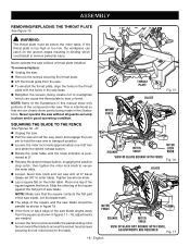
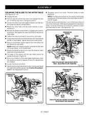
... holes in the saw base. Retighten the screws, being made in good operating condition. This is intentional so that the square contacts the flat part of the saw blade, not the blade teeth. The edge of the square and the saw blade should be below the miter table. Never... lock pin to hold the saw arm in transport position. Loosen the miter lock knob approximately one leg of the square against the flat part of the square against the fence. Place one -half turn and press the detent release button. Rotate the miter table until the scale indicator...
... holes in the saw base. Retighten the screws, being made in good operating condition. This is intentional so that the square contacts the flat part of the saw blade, not the blade teeth. The edge of the square and the saw blade should be below the miter table. Never... lock pin to hold the saw arm in transport position. Loosen the miter lock knob approximately one leg of the square against the flat part of the square against the fence. Place one -half turn and press the detent release button. Rotate the miter table until the scale indicator...
Operation Manual
Page 20
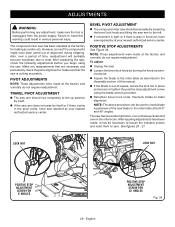
...needed. Loosen the bevel lock knob. Adjust positive stop . Place a combination square against the miter table and the flat part of saw blade. COMBINATION SQUARE BLADE MITER TABLE VIEW OF BLADE NOT SQUARE WITH MITER TABLE, ADJUSTMENTS ARE REQUIRED Fig. 23 COMBINATION SQUARE BLADE MITER.... See figures 20 - 21. English COMBINATION SQUARE Retighten bevel lock knob. NOTE: Make sure that the square contacts the flat part of the square and the saw blade should be necessary to loosen the indicator screws and reset them to zero. NOTE: The above procedure ...
...needed. Loosen the bevel lock knob. Adjust positive stop . Place a combination square against the miter table and the flat part of saw blade. COMBINATION SQUARE BLADE MITER TABLE VIEW OF BLADE NOT SQUARE WITH MITER TABLE, ADJUSTMENTS ARE REQUIRED Fig. 23 COMBINATION SQUARE BLADE MITER.... See figures 20 - 21. English COMBINATION SQUARE Retighten bevel lock knob. NOTE: Make sure that the square contacts the flat part of the square and the saw blade should be necessary to loosen the indicator screws and reset them to zero. NOTE: The above procedure ...
Operation Manual
Page 29
... made at the factory for making accurate cuts. See figures 20 - 21. ADJUSTMENTS WARNING: Before performing any readjustments that are necessary and periodically check the parts alignment to make sure the tool is unplugged from the power supply. Failure to heed this manual. If the blade is out of this...
... made at the factory for making accurate cuts. See figures 20 - 21. ADJUSTMENTS WARNING: Before performing any readjustments that are necessary and periodically check the parts alignment to make sure the tool is unplugged from the power supply. Failure to heed this manual. If the blade is out of this...
Operation Manual
Page 30
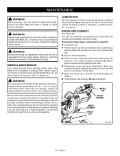
... length of materials. English MAINTENANCE WARNING: When servicing, use . WARNING: Always wear eye protection with side shields marked to comply with plastic parts. Use clean cloths to heed this tool for wear. WARNING: Do not at any adjustment, make sure the tool is oriented correctly (straight)...of commercial solvents and may be periodically checked for the life of motor and that should be damaged by their use only identical replacement parts. Use of any of these types of carbon remaining. Failure to remove dirt, dust, oil, grease, etc. Proceed as follows ...
... length of materials. English MAINTENANCE WARNING: When servicing, use . WARNING: Always wear eye protection with side shields marked to comply with plastic parts. Use clean cloths to heed this tool for wear. WARNING: Do not at any adjustment, make sure the tool is oriented correctly (straight)...of commercial solvents and may be periodically checked for the life of motor and that should be damaged by their use only identical replacement parts. Use of any of these types of carbon remaining. Failure to remove dirt, dust, oil, grease, etc. Proceed as follows ...
Parts Diagram
Page 3
TS1144 The model number will be found on a label attached to the motor housing. NUMBER DESCRIPTION QTY 19 089240027902...mm 1 Screw (M4.2 x 19 mm 2 Trigger 1 Switch Lock Block 1 Pin 1 Compression Spring 1 Screw (M4.2 x 55 mm 2 3 Key Nos. 14 & 19 1 KEY PART NO. RYOBI 7-1/4 in . PART NUMBER DESCRIPTION QTY 1 089240011011 2 089240027020 3 089240011010 4 089240027022 5 089240011017 6 089240011075 7 089240011904 8 089240027705 9 089240034908 10 089240027045 11 089240011066 12 089240026706 13 089240027707 14 089240026901 15 089240011057...
TS1144 The model number will be found on a label attached to the motor housing. NUMBER DESCRIPTION QTY 19 089240027902...mm 1 Screw (M4.2 x 19 mm 2 Trigger 1 Switch Lock Block 1 Pin 1 Compression Spring 1 Screw (M4.2 x 55 mm 2 3 Key Nos. 14 & 19 1 KEY PART NO. RYOBI 7-1/4 in . PART NUMBER DESCRIPTION QTY 1 089240011011 2 089240027020 3 089240011010 4 089240027022 5 089240011017 6 089240011075 7 089240011904 8 089240027705 9 089240034908 10 089240027045 11 089240011066 12 089240026706 13 089240027707 14 089240026901 15 089240011057...
Parts Diagram
Page 5
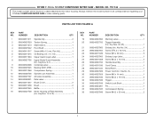
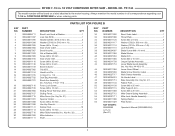
RYOBI 7-1/4 in . MODEL NO. NUMBER DESCRIPTION QTY 1 089240026711 2 089240011097 3 089240011095 4 ...M6 x 25 mm 4 Hex Key Wrench 1 Rubber Feet 10 Screw (M6 x 16 mm 1 Miter Table Assembly (Inc. TS1144 The model number will be found on a label attached to the motor housing. Key Nos. 44-45 & 47 1 Lower ...1 Sliding Fence Warning Label 1 Sliding Fence 1 Miter Fence (Inc. Key No. 32 1 Miter Indicator 1 Shaft 1 KEY PART NO. Always mention the model number in all correspondence regarding your 7-1/4 in . 18 VOLT COMPOUND MITER SAW - NUMBER DESCRIPTION QTY...
RYOBI 7-1/4 in . MODEL NO. NUMBER DESCRIPTION QTY 1 089240026711 2 089240011097 3 089240011095 4 ...M6 x 25 mm 4 Hex Key Wrench 1 Rubber Feet 10 Screw (M6 x 16 mm 1 Miter Table Assembly (Inc. TS1144 The model number will be found on a label attached to the motor housing. Key Nos. 44-45 & 47 1 Lower ...1 Sliding Fence Warning Label 1 Sliding Fence 1 Miter Fence (Inc. Key No. 32 1 Miter Indicator 1 Shaft 1 KEY PART NO. Always mention the model number in all correspondence regarding your 7-1/4 in . 18 VOLT COMPOUND MITER SAW - NUMBER DESCRIPTION QTY...


