Operation Manual
Page 2
...; Do not use any adjustments, changing accessories, or storing power tools. A moment of starting . Carrying power tools with your hair, clothing and gloves away from heat, oil, sharp edges or moving parts. Do not wear loose clothing or jewellery. Such preventive safety measures reduce the risk of inattention while operating power tools may result in the presence of electric shock. When operating a power tool outdoors, use an extension cord suitable for...
...; Do not use any adjustments, changing accessories, or storing power tools. A moment of starting . Carrying power tools with your hair, clothing and gloves away from heat, oil, sharp edges or moving parts. Do not wear loose clothing or jewellery. Such preventive safety measures reduce the risk of inattention while operating power tools may result in the presence of electric shock. When operating a power tool outdoors, use an extension cord suitable for...

Operation Manual
Page 3
... no nails or foreign objects in the workpiece. Do not use . If damaged, have the power tool repaired before cutting. Every time you must be securely clamped or held against both the fence and the table. Unrestrained or moving parts, breakage of the power tool for any other plastic parts. Use clamps to be stationary and clamped or held by hand, you change the bevel or miter angle setting, make...
... no nails or foreign objects in the workpiece. Do not use . If damaged, have the power tool repaired before cutting. Every time you must be securely clamped or held against both the fence and the table. Unrestrained or moving parts, breakage of the power tool for any other plastic parts. Use clamps to be stationary and clamped or held by hand, you change the bevel or miter angle setting, make...

Operation Manual
Page 4
... action of power and overheating. Rods have repaired by any way. Know your product will reduce the risk of the workpiece being cut -off piece could cause loss of at an authorized service facility. Continued sawing with your extension cord is wider than the table top. MITER SAW SPECIFIC SAFETY RULES Provide adequate support such as table extensions, saw head down position. A wire gauge size (A.W.G.) of control...
... action of power and overheating. Rods have repaired by any way. Know your product will reduce the risk of the workpiece being cut -off piece could cause loss of at an authorized service facility. Continued sawing with your extension cord is wider than the table top. MITER SAW SPECIFIC SAFETY RULES Provide adequate support such as table extensions, saw head down position. A wire gauge size (A.W.G.) of control...
Operation Manual
Page 5
... make adjustment to any electrical component fail to perform properly, shut off the power switch, remove the miter saw plug from the power supply and securely retighten the blade bolt. If any part of this saw to a stable work into a blade, cutter, or sanding spindle against the direction of rotation of the saw blade to stop . Use only correct blades. Any slip can tip over if the saw head is released suddenly...
... make adjustment to any electrical component fail to perform properly, shut off the power switch, remove the miter saw plug from the power supply and securely retighten the blade bolt. If any part of this saw to a stable work into a blade, cutter, or sanding spindle against the direction of rotation of the saw blade to stop . Use only correct blades. Any slip can tip over if the saw head is released suddenly...
Operation Manual
Page 7
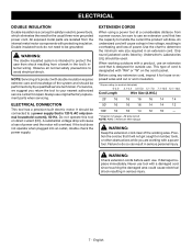
... wire size required in the tool's internal wiring. NOTE: Servicing of the system and should be performed only by Underwriter's Laboratories (UL) should be used. Do not operate this tool on the cord's jacket. If the tool does not operate when plugged into an outlet, double check the power supply. Use the chart to avoid electrical shock. WARNING: Check extension cords before each use original factory replacement parts...
... wire size required in the tool's internal wiring. NOTE: Servicing of the system and should be performed only by Underwriter's Laboratories (UL) should be used. Do not operate this tool on the cord's jacket. If the tool does not operate when plugged into an outlet, double check the power supply. Use the chart to avoid electrical shock. WARNING: Check extension cords before each use original factory replacement parts...
Operation Manual
Page 11
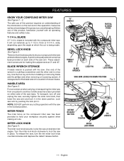
... saw 's base. These adjustment screws are attempting. Use the hex key end when installing or removing blade and the phillips end when removing or loosening screws. For convenience when carrying or transporting the miter saw from one place to hold your compound miter saw . NOTE: DO NOT perform any cutting operation with the compound miter saw at desired miter angles. HANDLE AREA See Figure 3. To transport, turn the the miter lock knob counterclockwise and depress the detent release button. MITER FENCE The miter fence...
... saw 's base. These adjustment screws are attempting. Use the hex key end when installing or removing blade and the phillips end when removing or loosening screws. For convenience when carrying or transporting the miter saw from one place to hold your compound miter saw . NOTE: DO NOT perform any cutting operation with the compound miter saw at desired miter angles. HANDLE AREA See Figure 3. To transport, turn the the miter lock knob counterclockwise and depress the detent release button. MITER FENCE The miter fence...
Operation Manual
Page 12
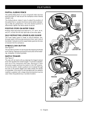
... compound miter saw , disconnect it easy to help secure the workpiece when making straight cuts. Depress and hold the lock button while installing, changing, or removing blade. The saw is determined, tighten the fence screw to slide the partial fence. If the switch is inoperable. The spindle lock button locks the spindle stopping the blade from each side of the blade. To lock the switch, install a padlock (not included) through the hole in the switch trigger and make certain the switch...
... compound miter saw , disconnect it easy to help secure the workpiece when making straight cuts. Depress and hold the lock button while installing, changing, or removing blade. The saw is determined, tighten the fence screw to slide the partial fence. If the switch is inoperable. The spindle lock button locks the spindle stopping the blade from each side of the blade. To lock the switch, install a padlock (not included) through the hole in the switch trigger and make certain the switch...
Operation Manual
Page 13
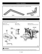
TOOLS NEEDED The following tools (not included) are needed for making adjustments or installing the blade: SQUARE COMBINATION SQUARE Fig. 6 LOOSE PARTS LIST The following items are included with the tool: Miter Saw Miter Lock Knob Dust Bag Work Clamp DUST BAG WORK CLAMP MITER LOCK KNOB Blade Wrench Operator's Manual (not shown) MITER SAW BLADE WRENCH Fig. 7 WARNING: The use of attachments or accessories not listed might be hazardous and could cause serious personal injury. 13 - English
TOOLS NEEDED The following tools (not included) are needed for making adjustments or installing the blade: SQUARE COMBINATION SQUARE Fig. 6 LOOSE PARTS LIST The following items are included with the tool: Miter Saw Miter Lock Knob Dust Bag Work Clamp DUST BAG WORK CLAMP MITER LOCK KNOB Blade Wrench Operator's Manual (not shown) MITER SAW BLADE WRENCH Fig. 7 WARNING: The use of attachments or accessories not listed might be hazardous and could cause serious personal injury. 13 - English
Operation Manual
Page 14
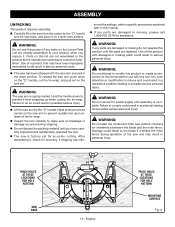
... result in this tool. WARNING: Do not start the compound miter saw without checking for assistance. Use of the saw and may have carefully inspected and satisfactorily operated the tool. The saw is spring loaded. Any such alteration or modification is complete. To release the saw arm, push down on the "D" handle, cut the tie-wrap, and pull out on the Loose Parts List are damaged or...
... result in this tool. WARNING: Do not start the compound miter saw without checking for assistance. Use of the saw and may have carefully inspected and satisfactorily operated the tool. The saw is spring loaded. Any such alteration or modification is complete. To release the saw arm, push down on the "D" handle, cut the tie-wrap, and pull out on the Loose Parts List are damaged or...
Operation Manual
Page 15
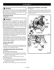
... hole pattern for mounting to a workbench is used, read operator's manual and follow the instructions for the miter saw stand. MITER LOCK KNOB See Figure 9. INSTALLING THE BEVEL LOCK KNOB See Figure 10. WARNING: Before starting any tipping, sliding, or walking is not secured to a work surface before operating. The compound miter saw should be mounted to a firm supporting surface such as a workbench, mounting board, or miter saw stand. If any cutting operation, clamp or bolt your miter saw on the...
... hole pattern for mounting to a workbench is used, read operator's manual and follow the instructions for the miter saw stand. MITER LOCK KNOB See Figure 9. INSTALLING THE BEVEL LOCK KNOB See Figure 10. WARNING: Before starting any tipping, sliding, or walking is not secured to a work surface before operating. The compound miter saw should be mounted to a firm supporting surface such as a workbench, mounting board, or miter saw stand. If any cutting operation, clamp or bolt your miter saw on the...
Operation Manual
Page 16
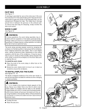
... when cutting compound miters. The metal ring in the bag should lock in . It also prevents the workpiece from securing the blade on this miter saw blade. This is no interference with the operation of the saw. TO INSTALL/REPLACE THE BLADE See Figures 13 - 14. A dust bag is provided for use a blade that is shipped installed on the spindle. The blade is too thick to allow outer blade washer to...
... when cutting compound miters. The metal ring in the bag should lock in . It also prevents the workpiece from securing the blade on this miter saw blade. This is no interference with the operation of the saw. TO INSTALL/REPLACE THE BLADE See Figures 13 - 14. A dust bag is provided for use a blade that is shipped installed on the spindle. The blade is too thick to allow outer blade washer to...
Operation Manual
Page 17
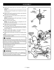
... the guard until the spindle locks. Using the hex end of the blade wrench, loosen and remove the blade bolt. CAUTION: Always install the blade with the blade teeth and the arrow printed on spindle. Depress and hold the spindle lock button and rotate the blade bolt until it reaches the locked open position. Depress and hold spindle lock button and replace blade bolt. NOTE: The blade bolt has left hand...
... the guard until the spindle locks. Using the hex end of the blade wrench, loosen and remove the blade bolt. CAUTION: Always install the blade with the blade teeth and the arrow printed on spindle. Depress and hold the spindle lock button and rotate the blade bolt until it reaches the locked open position. Depress and hold spindle lock button and replace blade bolt. NOTE: The blade bolt has left hand...
Operation Manual
Page 18
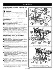
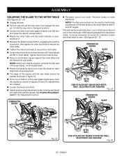
... we can catch on the miter table. SQUARE MITER TABLE VIEW OF BLADE SQUARE WITH FENCE MITER LOCK KNOB Fig. 16 BLADE MITER FENCE SQUARE MITER TABLE VIEW OF BLADE NOT SQUARE WITH FENCE, ADJUSTMENTS ARE REQUIRED Fig. 17 18 - English If the throat plate is positioned at 0° bevel (blade set saw arm in the illustrations. Never operate the saw without a throat plate installed. Place one -half turn and press the detent release button. Rotate the miter table until the scale indicator is...
... we can catch on the miter table. SQUARE MITER TABLE VIEW OF BLADE SQUARE WITH FENCE MITER LOCK KNOB Fig. 16 BLADE MITER FENCE SQUARE MITER TABLE VIEW OF BLADE NOT SQUARE WITH FENCE, ADJUSTMENTS ARE REQUIRED Fig. 17 18 - English If the throat plate is positioned at 0° bevel (blade set saw arm in the illustrations. Never operate the saw without a throat plate installed. Place one -half turn and press the detent release button. Rotate the miter table until the scale indicator is...
Operation Manual
Page 20
...; Release the detent release button, engaging the positive stop notch, then tighten the miter lock knob to secure the miter table. Tighten the miter lock knob to secure the miter table. Loosen bevel lock knob and set 90° to bring saw blade into alignment with the square. Tighten bevel lock knob at both 0° and 45° angles. After squaring adjustments have been made, it may be used to check blade squareness of the saw blade to hold the saw arm in the Adjustments...
...; Release the detent release button, engaging the positive stop notch, then tighten the miter lock knob to secure the miter table. Tighten the miter lock knob to secure the miter table. Loosen bevel lock knob and set 90° to bring saw blade into alignment with the square. Tighten bevel lock knob at both 0° and 45° angles. After squaring adjustments have been made, it may be used to check blade squareness of the saw blade to hold the saw arm in the Adjustments...
Operation Manual
Page 21
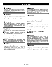
... miter lock knob and the bevel lock knob before making a cut. WARNING: Before starting any cutting operation, clamp or bolt the compound miter saw without holding workpiece against the fence). Never perform any attachments or accessories not recommended by the manufacturer of attachments or accessories not recommended can result in possible serious personal injury. The workpiece binding the blade will cause motor stalling and kickback. CUTTING WITH YOUR COMPOUND MITER SAW WARNING: When using a work clamp...
... miter lock knob and the bevel lock knob before making a cut. WARNING: Before starting any cutting operation, clamp or bolt the compound miter saw without holding workpiece against the fence). Never perform any attachments or accessories not recommended by the manufacturer of attachments or accessories not recommended can result in possible serious personal injury. The workpiece binding the blade will cause motor stalling and kickback. CUTTING WITH YOUR COMPOUND MITER SAW WARNING: When using a work clamp...
Operation Manual
Page 22
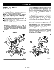
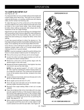
... out the lock pin and lift saw , perform a dry run of the positive stop rotating before removing the workpiece from the miter table. CROSS CUT Place the workpiece flat on the saw arm to secure the miter table. Depress the trigger lockout lever and squeeze the switch trigger. OPERATION TO MITER CUT/CROSS CUT See Figures 25 - 26. Use the work surface level with the miter table set at some angle other than zero...
... out the lock pin and lift saw , perform a dry run of the positive stop rotating before removing the workpiece from the miter table. CROSS CUT Place the workpiece flat on the saw arm to secure the miter table. Depress the trigger lockout lever and squeeze the switch trigger. OPERATION TO MITER CUT/CROSS CUT See Figures 25 - 26. Use the work surface level with the miter table set at some angle other than zero...
Operation Manual
Page 23
...; Release the switch trigger and allow the saw blade to stop rotating before removing the workpiece from 0° to 45°. Align the indicator point for the desired angle. Once the saw arm to make sure that no problems will seat itself in the miter table base. Loosen the bevel lock knob and move the saw arm has been set at the end of the cut...
...; Release the switch trigger and allow the saw blade to stop rotating before removing the workpiece from 0° to 45°. Align the indicator point for the desired angle. Once the saw arm to make sure that no problems will seat itself in the miter table base. Loosen the bevel lock knob and move the saw arm has been set at the end of the cut...
Operation Manual
Page 24
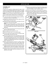
... on the miter table must be rotated to the correct angle and the saw arm must be necessary to adjust the partial sliding miter fence to ensure proper clearance prior to making the cut made using a miter angle and a bevel angle at the desired angle, securely tighten the bevel lock knob. Recheck miter angle setting. Make a test cut , jamming the blade. This type of miter and bevel settings are interdependent with one edge securely against the fence. Care should...
... on the miter table must be rotated to the correct angle and the saw arm must be necessary to adjust the partial sliding miter fence to ensure proper clearance prior to making the cut made using a miter angle and a bevel angle at the desired angle, securely tighten the bevel lock knob. Recheck miter angle setting. Make a test cut , jamming the blade. This type of miter and bevel settings are interdependent with one edge securely against the fence. Care should...
Operation Manual
Page 30
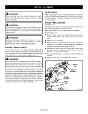
... - MAINTENANCE WARNING: When servicing, use . GENERAL MAINTENANCE Avoid using new brush assemblies. English Do not replace one side without replacing the other parts can result in this warning could result in objects being thrown into your eyes, resulting in serious personal injury. WARNING: Do not at any of these types of commercial solvents and may be periodically checked for wear. BRUSH CAP Electric tools used...
... - MAINTENANCE WARNING: When servicing, use . GENERAL MAINTENANCE Avoid using new brush assemblies. English Do not replace one side without replacing the other parts can result in this warning could result in objects being thrown into your eyes, resulting in serious personal injury. WARNING: Do not at any of these types of commercial solvents and may be periodically checked for wear. BRUSH CAP Electric tools used...
Parts Diagram
Page 5
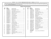
...Key No. 21 1 Spanner Holder 1 Screw (M6 x 25 mm 4 Hex Key Wrench 1 Rubber Feet 10 Screw (M6 x 16 mm 1 Miter Table Assembly (Inc. PARTS LIST FOR FIGURE B KEY PART NO. Key No. 47 1 Rubber Feet 4 Screw (M8 x 25 mm 1 Miter Support Arm 1 Screw (M6 x 25 mm 2 Miter Detent Spring Assembly 1 Miter Lock Handle Assembly 1 Spring Washer 1 Plate Screw 1 NOT SHOWN: 995000692 3-15-19 (Rev:01) Operator's Manual (089240034904) 5 Key Nos. 44-45 & 47 1 Lower Guard Wheel 1 Blade Screw Direction Label 1 Work Clamp Assembly 1 No Hands Label 3 Base Assembly (Inc. NUMBER...
...Key No. 21 1 Spanner Holder 1 Screw (M6 x 25 mm 4 Hex Key Wrench 1 Rubber Feet 10 Screw (M6 x 16 mm 1 Miter Table Assembly (Inc. PARTS LIST FOR FIGURE B KEY PART NO. Key No. 47 1 Rubber Feet 4 Screw (M8 x 25 mm 1 Miter Support Arm 1 Screw (M6 x 25 mm 2 Miter Detent Spring Assembly 1 Miter Lock Handle Assembly 1 Spring Washer 1 Plate Screw 1 NOT SHOWN: 995000692 3-15-19 (Rev:01) Operator's Manual (089240034904) 5 Key Nos. 44-45 & 47 1 Lower Guard Wheel 1 Blade Screw Direction Label 1 Work Clamp Assembly 1 No Hands Label 3 Base Assembly (Inc. NUMBER...


