Operation Manual
Page 11
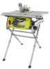
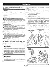
... set with the blade before plugging tool into the switch, lift the switch to prevent unauthorized and possible hazardous use by an insert called the throat plate. FEATURES OPERATING COMPONENTS The upper portion of the blade projects up through -sawing operations. Detailed instructions are provided in a safe, secure location. A scale on the...
... set with the blade before plugging tool into the switch, lift the switch to prevent unauthorized and possible hazardous use by an insert called the throat plate. FEATURES OPERATING COMPONENTS The upper portion of the blade projects up through -sawing operations. Detailed instructions are provided in a safe, secure location. A scale on the...
Operation Manual
Page 17
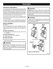
... HANDLE See Figure 9. Hold the nylon nut securely and turn the screw clockwise and tighten in place. English TO REMOVE/REPLACE THE THROAT PLATE See Figure 10. Lower the blade by turning the height/bevel adjusting handwheel counterclockwise. To remove the... throat plate, place your index finger in the hole and lift the front end pulling the throat plate out toward the front of the saw . To reinstall the throat plate, slip the tab into the hole on the back of the height/...
... HANDLE See Figure 9. Hold the nylon nut securely and turn the screw clockwise and tighten in place. English TO REMOVE/REPLACE THE THROAT PLATE See Figure 10. Lower the blade by turning the height/bevel adjusting handwheel counterclockwise. To remove the... throat plate, place your index finger in the hole and lift the front end pulling the throat plate out toward the front of the saw . To reinstall the throat plate, slip the tab into the hole on the back of the height/...
Operation Manual
Page 18
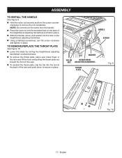
...FOR NON-THROUGH CUTTING Fig. 11 18 - English To place in riving knife "down" position for all nonthrough cutting: Remove the throat plate. Raise the saw blade by turning the height/bevel adjusting handwheel clockwise. Unlock the release lever by pulling it up. ...saw blade. Lock the release lever by pushing the lever down . Reinstall the throat plate. To place in the "up" position for non-through cutting: Remove the throat plate. Raise the saw blade by turning the height/bevel adjusting handwheel clockwise. Unlock ...
...FOR NON-THROUGH CUTTING Fig. 11 18 - English To place in riving knife "down" position for all nonthrough cutting: Remove the throat plate. Raise the saw blade by turning the height/bevel adjusting handwheel clockwise. Unlock the release lever by pulling it up. ...saw blade. Lock the release lever by pushing the lever down . Reinstall the throat plate. To place in the "up" position for non-through cutting: Remove the throat plate. Raise the saw blade by turning the height/bevel adjusting handwheel clockwise. Unlock ...
Operation Manual
Page 19
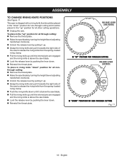
...open end into the middle hole of the machine. To install blade guard: Lift the guard lever up " position. Reinstall the throat plate. Push the front of the guard down toward the front of the machine. Check the blade guard assembly for through cuts. Unplug the saw...end on the flats on the arbor shaft. Insert the closed end wrench forward to the back of the saw blade and remove the throat plate. Make sure the bevel locking lever is securely tightened. OPEN END BLADE WRENCH CLOSED END BLADE WRENCH BLADE NUT WARNING: Always install ...
...open end into the middle hole of the machine. To install blade guard: Lift the guard lever up " position. Reinstall the throat plate. Push the front of the guard down toward the front of the machine. Check the blade guard assembly for through cuts. Unplug the saw...end on the flats on the arbor shaft. Insert the closed end wrench forward to the back of the saw blade and remove the throat plate. Make sure the bevel locking lever is securely tightened. OPEN END BLADE WRENCH CLOSED END BLADE WRENCH BLADE NUT WARNING: Always install ...
Operation Manual
Page 22
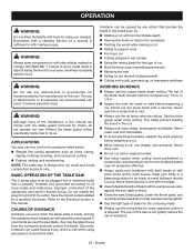
... will not fit the outlet. APPLICATIONS You may contact the blade. Have the correct outlet installed by any areas where saw , blade guard, under the throat plate, and any action that pinches the blade in the wood such as: Making a cut with incorrect blade depth Sawing into your body in...
... will not fit the outlet. APPLICATIONS You may contact the blade. Have the correct outlet installed by any areas where saw , blade guard, under the throat plate, and any action that pinches the blade in the wood such as: Making a cut with incorrect blade depth Sawing into your body in...
Operation Manual
Page 35
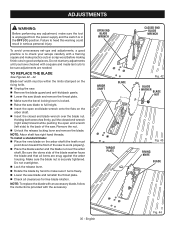
... on the riving knife. Unplug the saw. Remove the blade guard and anti-kickback pawls. Lower the saw blade and remove the throat plate. Make sure the bevel locking lever is in the OFF ( O ) position. Be sure the dome side of the saw to work properly). ... Arbor shaft has right hand threads. TO REPLACE THE BLADE See Figures 42 - 44. Failure to the back of the saw blade and reinstall the throat plate. Check all items are needed. Blade kerf width must point down toward the front of the blade washer faces the blade and that all...
... on the riving knife. Unplug the saw. Remove the blade guard and anti-kickback pawls. Lower the saw blade and remove the throat plate. Make sure the bevel locking lever is in the OFF ( O ) position. Be sure the dome side of the saw to work properly). ... Arbor shaft has right hand threads. TO REPLACE THE BLADE See Figures 42 - 44. Failure to the back of the saw blade and reinstall the throat plate. Check all items are needed. Blade kerf width must point down toward the front of the blade washer faces the blade and that all...
Operation Manual
Page 37
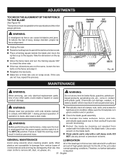
WARNING: Always wear eye protection with side shields marked to comply with a soft damp cloth. Make sure the throat plate is in good condition and in position. Check the blade guard assembly. To maintain the table surfaces, fence, and rails, periodically apply paste ...
WARNING: Always wear eye protection with side shields marked to comply with a soft damp cloth. Make sure the throat plate is in good condition and in position. Check the blade guard assembly. To maintain the table surfaces, fence, and rails, periodically apply paste ...

Parts Diagram
Page 3
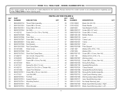
... Label - Always mention the model number in all correspondence regarding your 10 in . NUMBER DESCRIPTION QTY NO. RYOBI 10 in . NUMBER DESCRIPTION QTY 1 089037007713 Throat Plate Assembly 1 2 089015001001 Screw (M8 x 30 mm 1 3 089015001013 Screw (M8 x 35 mm 1 4... 080015001439 Middle Bracket 1 35 089037007019 Lever 1 36 089037007020 Clamp Lock 1 37 089037007021 Clamp 1 38 089037007097 Pad 1 39 089037007098 Plate Support 1 40 412011007 Washer (D5 x D12 x 1.5t 2 41 412021005 Washer (D5 2 42 089037007101 Screw (M5 x ...
... Label - Always mention the model number in all correspondence regarding your 10 in . NUMBER DESCRIPTION QTY NO. RYOBI 10 in . NUMBER DESCRIPTION QTY 1 089037007713 Throat Plate Assembly 1 2 089015001001 Screw (M8 x 30 mm 1 3 089015001013 Screw (M8 x 35 mm 1 4... 080015001439 Middle Bracket 1 35 089037007019 Lever 1 36 089037007020 Clamp Lock 1 37 089037007021 Clamp 1 38 089037007097 Pad 1 39 089037007098 Plate Support 1 40 412011007 Washer (D5 x D12 x 1.5t 2 41 412021005 Washer (D5 2 42 089037007101 Screw (M5 x ...
Parts Diagram 1
Page 3
... Label (Upper Barrier 1 53 089037007911 Inner Guard Warning Label 1 54 089110113913 No Hands Warning Label 2 55 089037007909 Blade Guard Warning Label - NUMBER DESCRIPTION QTY 1 089040002704 Throat Plate Assembly 1 2 089015001001 Screw (M8 x 30 mm 1 3 089015001013 Screw (M8 x 35 mm 1 4 089037007004 Nut (M8 2 5 410102702 Screw (1/4-20 x 7/8 in, Flat Hd 4 6 ...18 0101010501 Block 1 19 414011001 Spring Pin (D4 x 13 mm 2 20 410162701 Screw (1/4-20 x 3/4 in . Right 1 56 089037007910 Blade Guard Warning Label - RYOBI 10 in.
... Label (Upper Barrier 1 53 089037007911 Inner Guard Warning Label 1 54 089110113913 No Hands Warning Label 2 55 089037007909 Blade Guard Warning Label - NUMBER DESCRIPTION QTY 1 089040002704 Throat Plate Assembly 1 2 089015001001 Screw (M8 x 30 mm 1 3 089015001013 Screw (M8 x 35 mm 1 4 089037007004 Nut (M8 2 5 410102702 Screw (1/4-20 x 7/8 in, Flat Hd 4 6 ...18 0101010501 Block 1 19 414011001 Spring Pin (D4 x 13 mm 2 20 410162701 Screw (1/4-20 x 3/4 in . Right 1 56 089037007910 Blade Guard Warning Label - RYOBI 10 in.


