Operating Instructions
Page 8
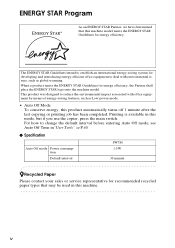
... STAR Guidelines for recommended recycled paper types that may be used in this machine. When a product meets the ENERGY STAR Guidelines for developing and introducing energy-efficient office equipment to change the default interval before entering Auto Off mode, see Auto Off Time in"User Tools..." ⇒ P.40 ❖ Specification Auto Off mode Power consumption Default interval FW780 1.0 W 30 minute -Recycled Paper Please contact your sales or service representative for energy efficiency. The ENERGY STAR Guidelines intend to reduce the...
... STAR Guidelines for recommended recycled paper types that may be used in this machine. When a product meets the ENERGY STAR Guidelines for developing and introducing energy-efficient office equipment to change the default interval before entering Auto Off mode, see Auto Off Time in"User Tools..." ⇒ P.40 ❖ Specification Auto Off mode Power consumption Default interval FW780 1.0 W 30 minute -Recycled Paper Please contact your sales or service representative for energy efficiency. The ENERGY STAR Guidelines intend to reduce the...
Service Manual
Page 13
... any adjustment or operation check has to the table. HEALTH SAFETY CONDITIONS 1. Always replace the ozone filters with water as first aid. Toner and developer are supplied with electrical voltage even if the main switch is operating. If any mechanical and electrical components during this period. Note that the copier...switch is turned on , the machine will suddenly start turnig to avoid touching those components with exterior covers off . 4. Be careful to perform the developer initialization. Keep hands away from electrified or mechanically driven components. 5.
... any adjustment or operation check has to the table. HEALTH SAFETY CONDITIONS 1. Always replace the ozone filters with water as first aid. Toner and developer are supplied with electrical voltage even if the main switch is operating. If any mechanical and electrical components during this period. Note that the copier...switch is turned on , the machine will suddenly start turnig to avoid touching those components with exterior covers off . 4. Be careful to perform the developer initialization. Keep hands away from electrified or mechanically driven components. 5.
Service Manual
Page 14
... not sealing them later, do not put more than 100 RAM packs per sealed box. b Do not incinerate the toner cartridge or the used toner, developer, and organic photoconductors according to local regulations. (These are non-toxic supplies.) 3. Dispose of replaced parts in order to dispose of used toner. Toner dust...
... not sealing them later, do not put more than 100 RAM packs per sealed box. b Do not incinerate the toner cartridge or the used toner, developer, and organic photoconductors according to local regulations. (These are non-toxic supplies.) 3. Dispose of replaced parts in order to dispose of used toner. Toner dust...
Service Manual
Page 15
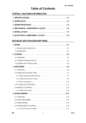
... Rev. 06/2004 OVERALL MACHINE INFORMATION 1. PAPER PATH 1-3 3. ELECTRICAL COMPONENT LAYOUT 1-8 DETAILED SECTION DESCRIPTIONS 1. CHARGE 2-3 2.1 OVERVIEW 2-3 2.2 CHARGE CORONA CIRCUIT 2-4 2.3 CORONA UNIT VENTILATION 2-5 3. MECHANICAL COMPONENT LAYOUT 1-6 5. DEVELOPMENT 2-13 4.1 OVERVIEW 2-13 4.2 DRIVE MECHANISM 2-14 4.3 CROSS-MIXING 2-15 4.4 TONER DENSITY CONTROL 2-16 4.4.1 Toner Near End Condition 2-17 SM i A163 SPECIFICATIONS 1-1 2. EXPOSURE 2-6 3.1 OVERVIEW 2-6 3.2 PAPER AND...
... Rev. 06/2004 OVERALL MACHINE INFORMATION 1. PAPER PATH 1-3 3. ELECTRICAL COMPONENT LAYOUT 1-8 DETAILED SECTION DESCRIPTIONS 1. CHARGE 2-3 2.1 OVERVIEW 2-3 2.2 CHARGE CORONA CIRCUIT 2-4 2.3 CORONA UNIT VENTILATION 2-5 3. MECHANICAL COMPONENT LAYOUT 1-6 5. DEVELOPMENT 2-13 4.1 OVERVIEW 2-13 4.2 DRIVE MECHANISM 2-14 4.3 CROSS-MIXING 2-15 4.4 TONER DENSITY CONTROL 2-16 4.4.1 Toner Near End Condition 2-17 SM i A163 SPECIFICATIONS 1-1 2. EXPOSURE 2-6 3.1 OVERVIEW 2-6 3.2 PAPER AND...
Service Manual
Page 16
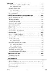
... ii SM CLEANING 2-24 6.1 OVERVIEW 2-24 6.2 COLLECTION OF USED TONER 2-25 7. Rev. 06/2004 4.4.2 Recovery From Toner (Near) End condition 2-17 4.4.3 Toner Density Sensor 2-18 4.5 DEVELOPMENT BIAS 2-19 4.5.1 Basic Concept 2-19 4.5.2 Manual Image Density Bias 2-19 4.6 TONER SUPPLY 2-20 5. IMAGE TRANSFER AND PAPER SEPARATION 2-21 5.1 PRE-TRANSFER LAMP (PTL 2-21 5.2 IMAGE...
... ii SM CLEANING 2-24 6.1 OVERVIEW 2-24 6.2 COLLECTION OF USED TONER 2-25 7. Rev. 06/2004 4.4.2 Recovery From Toner (Near) End condition 2-17 4.4.3 Toner Density Sensor 2-18 4.5 DEVELOPMENT BIAS 2-19 4.5.1 Basic Concept 2-19 4.5.2 Manual Image Density Bias 2-19 4.6 TONER SUPPLY 2-20 5. IMAGE TRANSFER AND PAPER SEPARATION 2-21 5.1 PRE-TRANSFER LAMP (PTL 2-21 5.2 IMAGE...
Service Manual
Page 25
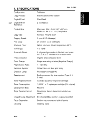
...) Reproduction Ratio: 1 : 1 (±0.5%) Exposure System: Slit exposure via fiber optic array Exposure Lamp: Fluorescent lamp (26 W) Development: Dual-component dry toner system (Type 410, 2 bags) Toner Replenishment: Cartridge system (750g toner/cartridge) Toner Consumption: 1,860 A1... or D copies per cartridge (6% original) Development Bias: Negative Toner Density Control: Direct toner density detection by induction sensor Image Density Adjustment: Development bias control + exposure control Paper Separation: Dual wire ac corona and pick...
...) Reproduction Ratio: 1 : 1 (±0.5%) Exposure System: Slit exposure via fiber optic array Exposure Lamp: Fluorescent lamp (26 W) Development: Dual-component dry toner system (Type 410, 2 bags) Toner Replenishment: Cartridge system (750g toner/cartridge) Toner Consumption: 1,860 A1... or D copies per cartridge (6% original) Development Bias: Negative Toner Density Control: Direct toner density detection by induction sensor Image Density Adjustment: Development bias control + exposure control Paper Separation: Dual wire ac corona and pick...
Service Manual
Page 29
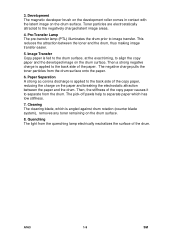
...the drum prior to the negatively charged latent image areas. 4. Then a strong negative charge is applied to align the copy paper and the developed image on the drum surface. 8. Paper Separation A strong ac corona discharge is applied to the back side of the copy paper, reducing... Transfer Copy paper is angled against drum rotation (counter blade system), removes any toner remaining on the drum surface. Development The magnetic developer brush on the development roller comes in contact with the latent image on the paper and breaking the electrostatic attraction between the toner and the...
...the drum prior to the negatively charged latent image areas. 4. Then a strong negative charge is applied to align the copy paper and the developed image on the drum surface. 8. Paper Separation A strong ac corona discharge is applied to the back side of the copy paper, reducing... Transfer Copy paper is angled against drum rotation (counter blade system), removes any toner remaining on the drum surface. Development The magnetic developer brush on the development roller comes in contact with the latent image on the paper and breaking the electrostatic attraction between the toner and the...
Service Manual
Page 30
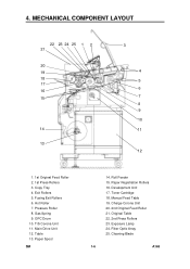
Gas Spring 9. Table 13. Roll Feeder 15. Exposure Lamp 24. Fiber Optic Array 25. Fusing Exit Rollers 6. Paper Spool SM 14. Development Unit 17. Manual Feed Table 19. Copy Tray 4. Paper Registration Rollers 16. Toner Cartridge 18. Original Table 22. 2nd Press Rollers 23. Hot Roller 7. Charge ...
Gas Spring 9. Table 13. Roll Feeder 15. Exposure Lamp 24. Fiber Optic Array 25. Fusing Exit Rollers 6. Paper Spool SM 14. Development Unit 17. Manual Feed Table 19. Copy Tray 4. Paper Registration Rollers 16. Toner Cartridge 18. Original Table 22. 2nd Press Rollers 23. Hot Roller 7. Charge ...
Service Manual
Page 31
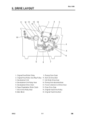
Original Feed Roller One Way Pulley 10. Toner Collection Coil Drive Gear 6. Main Motor 16. DRIVE LAYOUT Rev. 5/95 11 12 13 15 16 14 1 23 10 4 5 6 9 8 7 1. Original Feed Roller Pulley 9. Fusing Drive Sprocket/Gear 5. Development Drive Chain 13. Exit Unit Drive Belt 3. Drum Drive Gear 7. Development Unit 11. Paper Registration Roller Clutch 14. Original Feed Drive Pulley 8. 5. Fusing Drive Chain 2. Hot Roller Drive Gear 4. Development Unit Relay Gear 12. Drum Drive Relay Gear 15. Original Feed Drive Belt A163 1-7 SM
Original Feed Roller One Way Pulley 10. Toner Collection Coil Drive Gear 6. Main Motor 16. DRIVE LAYOUT Rev. 5/95 11 12 13 15 16 14 1 23 10 4 5 6 9 8 7 1. Original Feed Roller Pulley 9. Fusing Drive Sprocket/Gear 5. Development Drive Chain 13. Exit Unit Drive Belt 3. Drum Drive Gear 7. Development Unit 11. Paper Registration Roller Clutch 14. Original Feed Drive Pulley 8. 5. Fusing Drive Chain 2. Hot Roller Drive Gear 4. Development Unit Relay Gear 12. Drum Drive Relay Gear 15. Original Feed Drive Belt A163 1-7 SM
Service Manual
Page 32
...to the ozone filter. (DC Motor) 5 Magnetic Clutches Registration Drives the registration rollers. 30 Toner Supply Turns on to supply toner to the development unit. 31 Solenoids Pick-off Pawl Moves the pick-off pawls against the drum. 6 Switches Main Supplies power to the copier. 17 Original ...Open Indicates "Door Open" in the operation panel and prohibits the key operation. 29 Toner Density Detects the density of toner in the developer. 26 Original Registration Detects when the original lead edge passes at the front of the exposure glass. 4 Light Detects the intensity of ...
...to the ozone filter. (DC Motor) 5 Magnetic Clutches Registration Drives the registration rollers. 30 Toner Supply Turns on to supply toner to the development unit. 31 Solenoids Pick-off Pawl Moves the pick-off pawls against the drum. 6 Switches Main Supplies power to the copier. 17 Original ...Open Indicates "Door Open" in the operation panel and prohibits the key operation. 29 Toner Density Detects the density of toner in the developer. 26 Original Registration Detects when the original lead edge passes at the front of the exposure glass. 4 Light Detects the intensity of ...
Service Manual
Page 33
... remaining on the drum surface after cleaning. 1 Power Packs Charge/Bias/Grid Provides high voltage power for the charge Power Pack corona, charge grid, and development bias. 19 Transfer/ Separation Provides high voltage power for the transfer corona and separation. 16 Thermistors Hot Roller Monitors the hot roller's surface temperature. 8 Pressure...
... remaining on the drum surface after cleaning. 1 Power Packs Charge/Bias/Grid Provides high voltage power for the charge Power Pack corona, charge grid, and development bias. 19 Transfer/ Separation Provides high voltage power for the transfer corona and separation. 16 Thermistors Hot Roller Monitors the hot roller's surface temperature. 8 Pressure...
Service Manual
Page 48
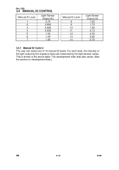
For each level, the intensity of 14 manual ID levels. This is shown in the above table. The development roller bias also varies. (See the section on development bias.) SM 2-12 A163 Rev. 5/95 3.4 MANUAL ID CONTROL Manual ID Level 1 2 3 4 5 6 7 Light Sensor Output [V] 0.78 0.892 0.899 0.938 1.02 1.24 1.45 Manual ID Level 8 9 10 11 12 13 14 Light Sensor Output [V] 1.53 1.73 1.93 2.13 2.33 2.52 2.72 3.4.1 Manual ID Control The user can select one of the light output by the exposure lamp (as measured by the light sensor) varies.
For each level, the intensity of 14 manual ID levels. This is shown in the above table. The development roller bias also varies. (See the section on development bias.) SM 2-12 A163 Rev. 5/95 3.4 MANUAL ID CONTROL Manual ID Level 1 2 3 4 5 6 7 Light Sensor Output [V] 0.78 0.892 0.899 0.938 1.02 1.24 1.45 Manual ID Level 8 9 10 11 12 13 14 Light Sensor Output [V] 1.53 1.73 1.93 2.13 2.33 2.52 2.72 3.4.1 Manual ID Control The user can select one of the light output by the exposure lamp (as measured by the light sensor) varies.
Service Manual
Page 49
The turning sleeve of the drum surface attract and hold the positively charged toner. The bias also controls image density. The doctor blade trims the developer to the desired thickness and creates backspill to minimize toner scattering. Therefore, a hole fitted with a filter has been added to the top of the unit ...
The turning sleeve of the drum surface attract and hold the positively charged toner. The bias also controls image density. The doctor blade trims the developer to the desired thickness and creates backspill to minimize toner scattering. Therefore, a hole fitted with a filter has been added to the top of the unit ...
Service Manual
Page 50
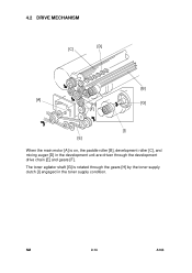
SM 2-14 A163 The toner agitator shaft [G] is on, the paddle roller [B], development roller [C], and mixing auger [D] in the development unit are driven through the gears [H] by the toner supply clutch [I] engaged in the toner supply condition. 4.2 DRIVE MECHANISM [D] [C] [B] [A] [H] [G] [F] [I] [E] When the main motor [A] is rotated through the development drive chain [E] and gears [F].
SM 2-14 A163 The toner agitator shaft [G] is on, the paddle roller [B], development roller [C], and mixing auger [D] in the development unit are driven through the gears [H] by the toner supply clutch [I] engaged in the toner supply condition. 4.2 DRIVE MECHANISM [D] [C] [B] [A] [H] [G] [F] [I] [E] When the main motor [A] is rotated through the development drive chain [E] and gears [F].
Service Manual
Page 51
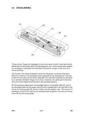
... plate [C]. However, the other part is trimmed off by the backspill plate is equal to the amount moved to develop the latent image on the toner and carrier particles. The developer that is split into two parts by the mixing auger [F], where it drops onto the paddle roller. As the... developer slides down the backspill plate to the paddle roller [D], part of developer moved to the right by the doctor blade and directed to generate the necessary triboelectric charge on the drum....
... plate [C]. However, the other part is trimmed off by the backspill plate is equal to the amount moved to develop the latent image on the toner and carrier particles. The developer that is split into two parts by the mixing auger [F], where it drops onto the paddle roller. As the... developer slides down the backspill plate to the paddle roller [D], part of developer moved to the right by the doctor blade and directed to generate the necessary triboelectric charge on the drum....
Service Manual
Page 52
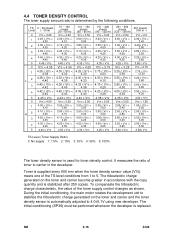
TS 0 ~ 50 sheets Level (~ 30 m) 0 VTS < 4.25 1 4.25 ≤ VTS < 4.30 N2 3 4.30 ≤ VTS < 4.35 4.35 ≤ VTS < 4.40 4 4.40 ≤ VTS < 4.45 5 4.45 ≤ VTS 0 VTS < 4.35 1 4.35 ≤ VTS < 4.38 L 2 4.38 ≤ VTS < 4.40 3 4.40 ≤ VTS < 4.42 4 4.42 ≤ VTS < 4.45 5 4.45 ≤ VTS 0 VTS < 4.00 1 4.00 ≤ VTS < 4.10 H2 4.10 ≤ VTS < 4.20 3 4.20 ≤ VTS < 4.30 4 4.30 ≤ VTS < 4.40 5 4.40 ≤ VTS 51 ~ 100 sheets (30 ~ 60 m) VTS < 4.00 4.00 ≤ VTS < 4.10 4.10 ≤ VTS < 4.20 4.20 ≤ VTS < 4.30 4.30 ≤...
TS 0 ~ 50 sheets Level (~ 30 m) 0 VTS < 4.25 1 4.25 ≤ VTS < 4.30 N2 3 4.30 ≤ VTS < 4.35 4.35 ≤ VTS < 4.40 4 4.40 ≤ VTS < 4.45 5 4.45 ≤ VTS 0 VTS < 4.35 1 4.35 ≤ VTS < 4.38 L 2 4.38 ≤ VTS < 4.40 3 4.40 ≤ VTS < 4.42 4 4.42 ≤ VTS < 4.45 5 4.45 ≤ VTS 0 VTS < 4.00 1 4.00 ≤ VTS < 4.10 H2 4.10 ≤ VTS < 4.20 3 4.20 ≤ VTS < 4.30 4 4.30 ≤ VTS < 4.40 5 4.40 ≤ VTS 51 ~ 100 sheets (30 ~ 60 m) VTS < 4.00 4.00 ≤ VTS < 4.10 4.10 ≤ VTS < 4.20 4.20 ≤ VTS < 4.30 4.30 ≤...
Service Manual
Page 53
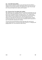
... not operate. 4.4.2 Recovery From Toner (Near) End Condition After replacing the toner cartridge (opening and closing the original feed unit), the main motor rotates the development unit for 1 minute. Then the add toner indicator will light and the machine will also take place after replacing toner cartridge. When in a row, the...
... not operate. 4.4.2 Recovery From Toner (Near) End Condition After replacing the toner cartridge (opening and closing the original feed unit), the main motor rotates the development unit for 1 minute. Then the add toner indicator will light and the machine will also take place after replacing toner cartridge. When in a row, the...
Service Manual
Page 54
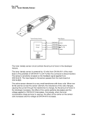
... the carrier particles decreases and the voltage applied to the sensor passes from CN104-A10. SM 2-18 A163 As the amount of toner in the developer mixture. The input signal to CN104-A10 decreases. The toner density sensor is used up, the effect of the coils changes, causing the current ...-B20 CN104-A10 CN104-B21 [12V] TS Control TS. FB GND Coils The toner density sensor circuit controls the amount of toner in the developer increases, the effect of CN104-A11 is 24 V when the connector is disconnected.) The sensor's sensitivity is a very small transformer with three coils...
... the carrier particles decreases and the voltage applied to the sensor passes from CN104-A10. SM 2-18 A163 As the amount of toner in the developer mixture. The input signal to CN104-A10 decreases. The toner density sensor is used up, the effect of the coils changes, causing the current ...-B20 CN104-A10 CN104-B21 [12V] TS Control TS. FB GND Coils The toner density sensor circuit controls the amount of toner in the developer increases, the effect of CN104-A11 is 24 V when the connector is disconnected.) The sensor's sensitivity is a very small transformer with three coils...
Service Manual
Page 55
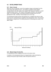
... is applied as shown by varying the exposure light intensity. (See the exposure section.) A163 2-19 SM In addition to the development bias, the image density is also controlled by the above chart. A negative bias that is a little larger than the residual charge is applied to the ...dark areas of the original. This leaves a negative charge pattern corresponding to the development roller. After exposure, however, a small residual charge of about --100 volts (for white paper) remains in dirty background on the copy...
... is applied as shown by varying the exposure light intensity. (See the exposure section.) A163 2-19 SM In addition to the development bias, the image density is also controlled by the above chart. A negative bias that is a little larger than the residual charge is applied to the ...dark areas of the original. This leaves a negative charge pattern corresponding to the development roller. After exposure, however, a small residual charge of about --100 volts (for white paper) remains in dirty background on the copy...
Service Manual
Page 56
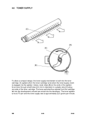
The toner particles thus ejected from the cartridge fall into the development unit and are mixed into the toner cartridge. SM 2-20 A163 As the agitator rotates, mylar strips [B] on the ends of the toner cartridge. An ... and the toner supply rate is approximately 22.5 grams per minute. 4.6 TONER SUPPLY [C] [B] [A] [B] To allow a compact design, the toner supply mechanism is built into the developer.
The toner particles thus ejected from the cartridge fall into the development unit and are mixed into the toner cartridge. SM 2-20 A163 As the agitator rotates, mylar strips [B] on the ends of the toner cartridge. An ... and the toner supply rate is approximately 22.5 grams per minute. 4.6 TONER SUPPLY [C] [B] [A] [B] To allow a compact design, the toner supply mechanism is built into the developer.
