
English Manual
Page 2
..., call the telephone number on the front cover of this manual and request a free replacement decal. Apply the decal in the location shown. TABLE OF CONTENTS WARNING DECAL PLACEMENT 2 IMPORTANT PRECAUTIONS 3 BEFORE YOU BEGIN 6 PART IDENTIFICATION CHART 7 ASSEMBLY 8 OPERATION AND ADJUSTMENT 14 HOW TO FOLD AND MOVE THE TREADMILL 20 TROUBLESHOOTING 21 EXERCISE GUIDELINES 23 PART LIST 24 EXPLODED DRAWING 25 ORDERING REPLACEMENT PARTS Back Cover LIMITED WARRANTY Back Cover WARNING DECAL PLACEMENT...
..., call the telephone number on the front cover of this manual and request a free replacement decal. Apply the decal in the location shown. TABLE OF CONTENTS WARNING DECAL PLACEMENT 2 IMPORTANT PRECAUTIONS 3 BEFORE YOU BEGIN 6 PART IDENTIFICATION CHART 7 ASSEMBLY 8 OPERATION AND ADJUSTMENT 14 HOW TO FOLD AND MOVE THE TREADMILL 20 TROUBLESHOOTING 21 EXERCISE GUIDELINES 23 PART LIST 24 EXPLODED DRAWING 25 ORDERING REPLACEMENT PARTS Back Cover LIMITED WARRANTY Back Cover WARNING DECAL PLACEMENT...
English Manual
Page 3
... jumps in damage to the control system of high speeds. Never move the walking belt while the power is being administered. 8. Never start the treadmill while you are used only by or through the use the treadmill in any surface that could result in speed. 3 The treadmill is not working properly. (See TROUBLESHOOTING on page 16). 18. Adjust the speed in a garage or covered patio, or near water...
... jumps in damage to the control system of high speeds. Never move the walking belt while the power is being administered. 8. Never start the treadmill while you are used only by or through the use the treadmill in any surface that could result in speed. 3 The treadmill is not working properly. (See TROUBLESHOOTING on page 16). 18. Adjust the speed in a garage or covered patio, or near water...
English Manual
Page 4
... before clean- When folding or moving the treadmill, make sure that the storage latch is not a medical device. Servicing other than the procedures in the storage position. 24. If you feel faint or if you experience pain while exercising, stop immediately and cool down. The heart rate monitor is holding the frame securely in this manual. Always remove the key, press the power switch into any object into...
... before clean- When folding or moving the treadmill, make sure that the storage latch is not a medical device. Servicing other than the procedures in the storage position. 24. If you feel faint or if you experience pain while exercising, stop immediately and cool down. The heart rate monitor is holding the frame securely in this manual. Always remove the key, press the power switch into any object into...
English Manual
Page 6
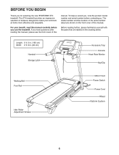
... PROFORM® ZT4 treadmill. Length: 5 ft. 5 in. (165 cm) Width: 2 ft. 9 in the drawing below. BEFORE YOU BEGIN Thank you use the treadmill. The model number and the location of features designed to make your benefit, read this manual. The ZT4 treadmill provides an impressive selection of the serial number decal are labeled in . (84 cm) Handrail Storage Latch Accessory Tray Console Heart Rate Monitor Key/Clip Walking Belt Foot Rail Idler Roller Adjustment Screws Motor Hood Power Switch Power Cord...
... PROFORM® ZT4 treadmill. Length: 5 ft. 5 in. (165 cm) Width: 2 ft. 9 in the drawing below. BEFORE YOU BEGIN Thank you use the treadmill. The model number and the location of features designed to make your benefit, read this manual. The ZT4 treadmill provides an impressive selection of the serial number decal are labeled in . (84 cm) Handrail Storage Latch Accessory Tray Console Heart Rate Monitor Key/Clip Walking Belt Foot Rail Idler Roller Adjustment Screws Motor Hood Power Switch Power Cord...
English Manual
Page 8
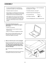
... parts, see the front cover of this manual) and register your warranty •• saves you time if you ever need to contact Customer Care •• allows us to notify you of the Base (74). B 74 A Tie 63 70 8 Then, remove and discard the screws and the shipping bracket (not shown) on the right side of upgrades...
... parts, see the front cover of this manual) and register your warranty •• saves you time if you ever need to contact Customer Care •• allows us to notify you of the Base (74). B 74 A Tie 63 70 8 Then, remove and discard the screws and the shipping bracket (not shown) on the right side of upgrades...
English Manual
Page 11
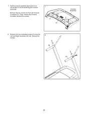
Remove the two screws (C) from the Left and Right Handrails (59, 64). Remove the four indicated screws (D) from the Console Crossbar (61). 7. Discard the screws. 7 C 61 Console Assembly C 8. Then, remove the Console Crossbar. Discard the screws. 8 D 59 D 64 11 Set the console assembly face down on a soft surface to avoid scratching the console assembly.
Remove the two screws (C) from the Left and Right Handrails (59, 64). Remove the four indicated screws (D) from the Console Crossbar (61). 7. Discard the screws. 7 C 61 Console Assembly C 8. Then, remove the Console Crossbar. Discard the screws. 8 D 59 D 64 11 Set the console assembly face down on a soft surface to avoid scratching the console assembly.

English Manual
Page 12
.... Start all four Screws, and then tighten them. If they do not, turn one connector and try again. 9. Firmly tighten the two 5/16" x 3/4" Screws (5) and the two 5/16" x 3" Screws (7). 9 8 23 7 5 66 61 8 23 7 76 5 10. Attach the Console Crossbar (61) to the ground wire on the Console Crossbar (61). 10 Console Assembly Console Wire 63 64 Ground Wires Wire 61 Console Tie Wire 63 12 Connect the Upright Wire (63) to the console wire.
.... Start all four Screws, and then tighten them. If they do not, turn one connector and try again. 9. Firmly tighten the two 5/16" x 3/4" Screws (5) and the two 5/16" x 3" Screws (7). 9 8 23 7 5 66 61 8 23 7 76 5 10. Attach the Console Crossbar (61) to the ground wire on the Console Crossbar (61). 10 Console Assembly Console Wire 63 64 Ground Wires Wire 61 Console Tie Wire 63 12 Connect the Upright Wire (63) to the console wire.
English Manual
Page 13
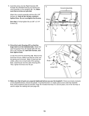
... x 3/4" Screws (8); Firmly tighten the six 3/8" x 3 1/4" Screws (2). 11 Wires Hole Console Assembly Wires 4 4 64 4 76 4 4 66 12. Make sure that the large hole is used to the Left Upright (66) with ten #8 x 3/4" Screws (4). See step 5. start both Screws, and then tighten them . one on the Uprights (66, 76). Insert the wires into the Latch Housing (67). Start all parts are two collars, place one of the hex keys is on the treadmill...
... x 3/4" Screws (8); Firmly tighten the six 3/8" x 3 1/4" Screws (2). 11 Wires Hole Console Assembly Wires 4 4 64 4 76 4 4 66 12. Make sure that the large hole is used to the Left Upright (66) with ten #8 x 3/4" Screws (4). See step 5. start both Screws, and then tighten them . one on the Uprights (66, 76). Insert the wires into the Latch Housing (67). Start all parts are two collars, place one of the hex keys is on the treadmill...
English Manual
Page 14
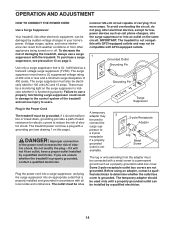
... suppressor to users. Use only a surge suppressor that is properly grounded, contact a qualified electrician. The surge suppressor must have a proper outlet installed by sudden voltage changes in damage to the control system of electric shock. nominal 120-volt circuit capable of electric shock. The treadmill power cord has a plug with a metal screw to determine whether the outlet box cover is functioning...
... suppressor to users. Use only a surge suppressor that is properly grounded, contact a qualified electrician. The surge suppressor must have a proper outlet installed by sudden voltage changes in damage to the control system of electric shock. nominal 120-volt circuit capable of electric shock. The treadmill power cord has a plug with a metal screw to determine whether the outlet box cover is functioning...
English Manual
Page 15
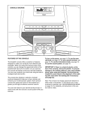
...). Each workout controls the speed and incline of the walking belt, and center the walking belt if necessary (see page 19. When you select the manual mode of the console, you exercise, the console will display continuous exercise feedback. You can change the speed and incline of the treadmill with the console’'s sound system while you through an effective exercise session. To turn on the power, see THE INFORMATION MODE on the face of a button...
...). Each workout controls the speed and incline of the walking belt, and center the walking belt if necessary (see page 19. When you select the manual mode of the console, you exercise, the console will display continuous exercise feedback. You can change the speed and incline of the treadmill with the console’'s sound system while you through an effective exercise session. To turn on the power, see THE INFORMATION MODE on the face of a button...
English Manual
Page 16
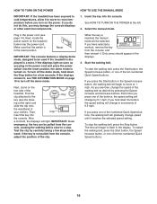
... be selected. If you press one of the treadmill. Next, locate the power switch on the foot rails of the ten numbered Quick Speed buttons. Reset IMPORTANT: The console features a display demo mode, designed to the key (see page 14). Next, stand on the treadmill frame near the power cord. ward; HOW TO USE THE MANUAL MODE 1. To start the walking belt, press the Start button, the Speed increase button, or one of the walking belt as you plug in the...
... be selected. If you press one of the treadmill. Next, locate the power switch on the foot rails of the ten numbered Quick Speed buttons. Reset IMPORTANT: The console features a display demo mode, designed to the key (see page 14). Next, stand on the treadmill frame near the power cord. ward; HOW TO USE THE MANUAL MODE 1. To start the walking belt, press the Start button, the Speed increase button, or one of the walking belt as you plug in the...
English Manual
Page 17
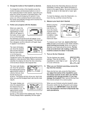
... or lower right display. In addition, make sure that you select the manual mode, a track representing 1/4 mile (400 m) will appear in the workout instead of the numbered Quick Incline buttons, the incline will show the elapsed time and the distance that your workout. For the most interested in viewing. The incline must be at zero when you fold the treadmill to the storage position, or you have walked...
... or lower right display. In addition, make sure that you select the manual mode, a track representing 1/4 mile (400 m) will appear in the workout instead of the numbered Quick Incline buttons, the incline will show the elapsed time and the distance that your workout. For the most interested in viewing. The incline must be at zero when you fold the treadmill to the storage position, or you have walked...
English Manual
Page 18
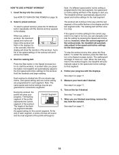
... walking belt. Each workout is divided into the console. To restart the workout, press the Start button or the Speed increase button. When the next segment of the workout will automatically adjust to the speed and incline settings for each segment, a series of tones will begin walking. HOW TO USE A PRESET WORKOUT 1. Insert the key into 30 one incline setting are nished exercising, remove the key from the console. When you select a workout, the maximum speed and incline settings...
... walking belt. Each workout is divided into the console. To restart the workout, press the Start button or the Speed increase button. When the next segment of the workout will automatically adjust to the speed and incline settings for each segment, a series of tones will begin walking. HOW TO USE A PRESET WORKOUT 1. Insert the key into 30 one incline setting are nished exercising, remove the key from the console. When you select a workout, the maximum speed and incline settings...
English Manual
Page 19
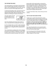
... buttons will show the total number of hours that the treadmill has been used if the treadmill is displayed in the lower right display while the information mode is turned on your local electronics store. THE INFORMATION MODE The console features an information mode that keeps track of treadmill usage information and allows you to be shown: power switch into the reset position, and insert the key into the console. When the information mode is fully plugged...
... buttons will show the total number of hours that the treadmill has been used if the treadmill is displayed in the lower right display while the information mode is turned on your local electronics store. THE INFORMATION MODE The console features an information mode that keeps track of treadmill usage information and allows you to be shown: power switch into the reset position, and insert the key into the console. When the information mode is fully plugged...

English Manual
Page 20
... frame. Keep the treadmill out of the treadmill with your back straight. Bend your legs and keep your right hand. HOW TO FOLD AND MOVE THE TREADMILL HOW TO FOLD THE TREADMILL HOW TO MOVE THE TREADMILL Before folding the treadmill, adjust the incline to the left and hold the frame by the arrow below. Remove the key and unplug the power cord. Pull the latch knob to the left...
... frame. Keep the treadmill out of the treadmill with your back straight. Bend your legs and keep your right hand. HOW TO FOLD AND MOVE THE TREADMILL HOW TO FOLD THE TREADMILL HOW TO MOVE THE TREADMILL Before folding the treadmill, adjust the incline to the left and hold the frame by the arrow below. Remove the key and unplug the power cord. Pull the latch knob to the left...
English Manual
Page 21
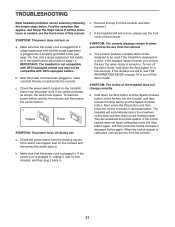
... console, and then release the Stop button and the Speed increase button. If the switch protrudes as shown, the switch has tripped. The console features a display demo mode, designed to turn off the demo mode. Next, press the Stop button and then press the Incline increase or decrease button. SYMPTOM: The power does not turn off during use c. After the power cord has been plugged in , unplug it, wait for a few seconds. The treadmill will recalibrate the incline...
... console, and then release the Stop button and the Speed increase button. If the switch protrudes as shown, the switch has tripped. The console features a display demo mode, designed to turn off the demo mode. Next, press the Stop button and then press the Incline increase or decrease button. SYMPTOM: The power does not turn off during use c. After the power cord has been plugged in , unplug it, wait for a few seconds. The treadmill will recalibrate the incline...
English Manual
Page 22
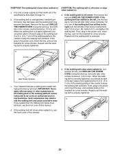
... edge of a turn . Your treadmill features a walking belt coated with high-performance lubricant. b. Then, plug in . Using the hex key, turn both idler roller screws clockwise, 1/4 of this manual. b 22 SYMPTOM: The walking belt slows when walked on , rst remove the key and UNPLUG THE POWER CORD. Remove the key and UNPLUG THE POWER CORD. IMPORTANT: Never apply silicone spray or other substances to the walking belt or the walking platform unless instructed to overtighten the walking belt.
... edge of a turn . Your treadmill features a walking belt coated with high-performance lubricant. b. Then, plug in . Using the hex key, turn both idler roller screws clockwise, 1/4 of this manual. b 22 SYMPTOM: The walking belt slows when walked on , rst remove the key and UNPLUG THE POWER CORD. Remove the key and UNPLUG THE POWER CORD. IMPORTANT: Never apply silicone spray or other substances to the walking belt or the walking platform unless instructed to overtighten the walking belt.
English Manual
Page 23
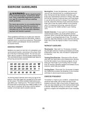
... rounded off to find your heart rate as a guide to the nearest ten years). If your body begin to five workouts each week, with your heart rate in your exercise program. For maximum fat burning, exercise with pre-existing health problems. The heart rate monitor is especially important for aerobic exercise. A warm-up to use your age at least one day of the chart (ages are essential for...
... rounded off to find your heart rate as a guide to the nearest ten years). If your body begin to five workouts each week, with your heart rate in your exercise program. For maximum fat burning, exercise with pre-existing health problems. The heart rate monitor is especially important for aerobic exercise. A warm-up to use your age at least one day of the chart (ages are essential for...

English Manual
Page 24
... 2 Belt Guide 31 1 Drive Roller/Pulley 32 1 3/8" x 1 1/2" Bolt 33 2 Round Handrail Cap 34 8 #8 x 3/4" Tek Screw 35 1 Drive Motor 36 1 Controller 37 1 Controller Plate 38 1 Frame 39 1 Walking Platform 40 1 Walking Belt 41 1 Right Foot Rail 42 1 Idler Roller 43 1 Left Rear Foot 44 4 Wire Tie 45 1 Drive Motor Belt 46 1 Right Rear Foot 47 8 #10 Flat Washer 48 1 Motor Hood 49 1 Incline Motor 50 2 Lift Frame Bushing 51 1 Lift Frame 52 1 Belly Pan 53 1 Power Cord Grommet...
... 2 Belt Guide 31 1 Drive Roller/Pulley 32 1 3/8" x 1 1/2" Bolt 33 2 Round Handrail Cap 34 8 #8 x 3/4" Tek Screw 35 1 Drive Motor 36 1 Controller 37 1 Controller Plate 38 1 Frame 39 1 Walking Platform 40 1 Walking Belt 41 1 Right Foot Rail 42 1 Idler Roller 43 1 Left Rear Foot 44 4 Wire Tie 45 1 Drive Motor Belt 46 1 Right Rear Foot 47 8 #10 Flat Washer 48 1 Motor Hood 49 1 Incline Motor 50 2 Lift Frame Bushing 51 1 Lift Frame 52 1 Belly Pan 53 1 Power Cord Grommet...

English Manual
Page 28
... drive motor are warranted for a minimal trip charge. ICON’'s obligation under this manual) LIMITED WARRANTY IMPORTANT: To protect your tness equipment with an extended service plan, see page 5. For in-home service, the customer will automatically be voided if the product is in lieu of any and all instructions in this manual) •• the key number and description of the replacement part...
... drive motor are warranted for a minimal trip charge. ICON’'s obligation under this manual) LIMITED WARRANTY IMPORTANT: To protect your tness equipment with an extended service plan, see page 5. For in-home service, the customer will automatically be voided if the product is in lieu of any and all instructions in this manual) •• the key number and description of the replacement part...


