

English Manual
Page 1
... parts, we will provide immediate assistance, free of charge. If you have questions, or if there are committed to providing complete customer satisfaction. MST CAUTION Read all precautions and instructions in the space above for future reference. Model No. PFSY59001 Serial No. Write the serial number in this manual before using this manual for future reference. TO AVOID DELAYS, PLEASE CALL DIRECT...
... parts, we will provide immediate assistance, free of charge. If you have questions, or if there are committed to providing complete customer satisfaction. MST CAUTION Read all precautions and instructions in the space above for future reference. Model No. PFSY59001 Serial No. Write the serial number in this manual before using this manual for future reference. TO AVOID DELAYS, PLEASE CALL DIRECT...
English Manual
Page 2
PROFORM is a registered trademark of this manual. TABLE OF CONTENTS IMPORTANT PRECAUTIONS 3 BEFORE YOU BEGIN 4 ASSEMBLY 5 ADJUSTMENTS 21 WEIGHT RESISTANCE CHART 23 TROUBLE-SHOOTING AND MAINTENANCE 24 CABLE DIAGRAMS 25 ORDERING REPLACEMENT PARTS Back Cover LIMITED WARRANTY Back Cover Note: A PART IDENTIFICATION CHART and a PART LIST/EXPLODED DRAWING are attached to the center of ICON Health & Fitness, Inc. 2 Remove the PART IDENTIFICATION CHART and the PART LIST/EXPLODED DRAWING before beginning assembly.
PROFORM is a registered trademark of this manual. TABLE OF CONTENTS IMPORTANT PRECAUTIONS 3 BEFORE YOU BEGIN 4 ASSEMBLY 5 ADJUSTMENTS 21 WEIGHT RESISTANCE CHART 23 TROUBLE-SHOOTING AND MAINTENANCE 24 CABLE DIAGRAMS 25 ORDERING REPLACEMENT PARTS Back Cover LIMITED WARRANTY Back Cover Note: A PART IDENTIFICATION CHART and a PART LIST/EXPLODED DRAWING are attached to the center of ICON Health & Fitness, Inc. 2 Remove the PART IDENTIFICATION CHART and the PART LIST/EXPLODED DRAWING before beginning assembly.

English Manual
Page 3
... especially important for home use the weight system in the location shown. Make sure all parts are on all instructions before using. Replace any commercial, rental, or institutional setting. 4. The weights will fall with pre-existing health problems. Read all of the pulleys. 14. Always disconnect the lat bar from the weight system when performing an exercise that could cause the weight system to support a a maximum user weight of all times...
... especially important for home use the weight system in the location shown. Make sure all parts are on all instructions before using. Replace any commercial, rental, or institutional setting. 4. The weights will fall with pre-existing health problems. Read all of the pulleys. 14. Always disconnect the lat bar from the weight system when performing an exercise that could cause the weight system to support a a maximum user weight of all times...

English Manual
Page 4
.... The model number is to achieve the specific results you for selecting the versatile PROFORM® 960 weight system. High Pulley Station Lat Bar Ab Pulley Station WARNING DECAL Press Arms Seat Leg Press Weight Stack ASSEMBLED DIMENSIONS: Height: 76.0 in . Mountain Time (excluding holidays). To help you to tone your body, build dramatic muscle size and strength, or improve your benefit, read this manual). Before reading further, please review the drawing...
.... The model number is to achieve the specific results you for selecting the versatile PROFORM® 960 weight system. High Pulley Station Lat Bar Ab Pulley Station WARNING DECAL Press Arms Seat Leg Press Weight Stack ASSEMBLED DIMENSIONS: Height: 76.0 in . Mountain Time (excluding holidays). To help you to tone your body, build dramatic muscle size and strength, or improve your benefit, read this manual). Before reading further, please review the drawing...

English Manual
Page 5
... small parts may want to Identify Parts To help of evenings. Seat Assembly-During the final stage you have divided the assembly process into four stages. ASSEMBLY Make Assembly Easier! Select a Location for that connect the arms to read the information on the floor and use it has been pre-attached. Note: Assembly will go smoothly. By setting aside plenty of its weight and size, the weight system...
... small parts may want to Identify Parts To help of evenings. Seat Assembly-During the final stage you have divided the assembly process into four stages. ASSEMBLY Make Assembly Easier! Select a Location for that connect the arms to read the information on the floor and use it has been pre-attached. Note: Assembly will go smoothly. By setting aside plenty of its weight and size, the weight system...

English Manual
Page 6
... than it . Locate and open the parts bags labeled "FRAME ASSEMBLY." 92 83 92 See the inset drawing. Be sure the Upright is in the position shown. Do not tighten the Nylon Locknuts yet. Do not tighten the Nylon Locknuts yet. Make sure the Plastic Bushing (52) is attached in the top of 3 the Butterfly Front Leg (3). Attach the Butterfly...
... than it . Locate and open the parts bags labeled "FRAME ASSEMBLY." 92 83 92 See the inset drawing. Be sure the Upright is in the position shown. Do not tighten the Nylon Locknuts yet. Do not tighten the Nylon Locknuts yet. Make sure the Plastic Bushing (52) is attached in the top of 3 the Butterfly Front Leg (3). Attach the Butterfly...
English Manual
Page 10
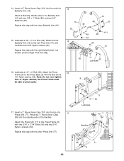
Attach a Butterfly Handle (53) to the Butterfly Arm (10) with the other Press Arm (77). 8 68 6 36 Lubricate 101 Handles 86 64 96 77 8 10 Repeat this step with two 3/8" x 1" Bolts (84) and two 3/8" Washers (48). Press two 1" Round Inner Caps (86) into the end of a Butterfly Arm (10). Lubricate a 1/2" x 4" Bolt (68). Lubricate a 3/8" x 3 1/4" Bolt (62). Repeat this step with the right Butterfly Arm (not shown) and...
Attach a Butterfly Handle (53) to the Butterfly Arm (10) with the other Press Arm (77). 8 68 6 36 Lubricate 101 Handles 86 64 96 77 8 10 Repeat this step with two 3/8" x 1" Bolts (84) and two 3/8" Washers (48). Press two 1" Round Inner Caps (86) into the end of a Butterfly Arm (10). Lubricate a 1/2" x 4" Bolt (68). Lubricate a 3/8" x 3 1/4" Bolt (62). Repeat this step with the right Butterfly Arm (not shown) and...

English Manual
Page 11
... 21 50 87 32 27 73 1 11 Lubricate a 3/8" x 3" Bolt (88). Attach the Press Leg Lever (90) to the bracket on the Butterfly Upright (1) with the Bolt and a 1/2" Nylon Jamnut (36). Locate and open the parts bags labeled "CABLE ASSEMBLY" and "PULLEYS." Wrap the Butterfly Cable (73) over tighten the Nylon Jamnut; Note: Do not over tighten the bolts and nuts attaching the pulleys. Insert two 2" Square Inner Caps (28...
... 21 50 87 32 27 73 1 11 Lubricate a 3/8" x 3" Bolt (88). Attach the Press Leg Lever (90) to the bracket on the Butterfly Upright (1) with the Bolt and a 1/2" Nylon Jamnut (36). Locate and open the parts bags labeled "CABLE ASSEMBLY" and "PULLEYS." Wrap the Butterfly Cable (73) over tighten the Nylon Jamnut; Note: Do not over tighten the bolts and nuts attaching the pulleys. Insert two 2" Square Inner Caps (28...

English Manual
Page 12
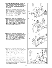
Wrap the Butterfly Cable (73) around a 3 1/2" Pulley (24). Locate the Ab Cable (47). Attach the Butterfly Cable (73) to the bracket on the Butterfly Upright (1) with a 3/8" x 2" Bolt (54) and a 3/8" Nylon Locknut (50). Remove the preassembled 3/8" x 2" Bolts (54) from one set of the Adjustable Pulley Plates (23) with a 3/8" x 2 1/2" Bolt (87) and a 3/8" Nylon Locknut (50). Attach the Pulley and a Large Cable Trap (32) to the Left Pivot Arm 24 (71) with...
Wrap the Butterfly Cable (73) around a 3 1/2" Pulley (24). Locate the Ab Cable (47). Attach the Butterfly Cable (73) to the bracket on the Butterfly Upright (1) with a 3/8" x 2" Bolt (54) and a 3/8" Nylon Locknut (50). Remove the preassembled 3/8" x 2" Bolts (54) from one set of the Adjustable Pulley Plates (23) with a 3/8" x 2 1/2" Bolt (87) and a 3/8" Nylon Locknut (50). Attach the Pulley and a Large Cable Trap (32) to the Left Pivot Arm 24 (71) with...

English Manual
Page 14
Locate the Weight Cable (72). Note that one end 30 of the Pulley. 3 24 54 4 72 50 Bracket 31. Wrap the Weight Cable (72) around a 3 1/2" Pulley (24), back through the hole in the Leg Lever, and through the upper hole in the Butterfly Front Leg (3). Attach the 3 1/2" Pulley (24) and two 5/8" x 1/2" Bushings (99) to the bracket with a 3/8" x 2" Bolt...54 4 50 Bracket 14 Lay the Weight Cable (72) inside the bracket on the Butterfly Base (4) in the groove of the Weight Cable has a bolt on it . Attach a 3 1/2" Pulley (24) to the Leg Lever (41) with a 3/8" ...
Locate the Weight Cable (72). Note that one end 30 of the Pulley. 3 24 54 4 72 50 Bracket 31. Wrap the Weight Cable (72) around a 3 1/2" Pulley (24), back through the hole in the Leg Lever, and through the upper hole in the Butterfly Front Leg (3). Attach the 3 1/2" Pulley (24) and two 5/8" x 1/2" Bushings (99) to the bracket with a 3/8" x 2" Bolt...54 4 50 Bracket 14 Lay the Weight Cable (72) inside the bracket on the Butterfly Base (4) in the groove of the Weight Cable has a bolt on it . Attach a 3 1/2" Pulley (24) to the Leg Lever (41) with a 3/8" ...
English Manual
Page 17
... side of the Press Leg Lever (90) with a 3/8" x 5 1/2" Bolt (55) and a 3/8" Nylon Locknut (50). Locate the Leg Press Cable (75). Attach the Pulley and a Cable Trap (25) to the indicated side of the Press Base (6) with a 3/8" x 6" Bolt (59) and a 3/8" Nylon Locknut (50). Be sure that was removed in the direction shown. Do not tighten the Nylon Locknut yet. Wrap the Leg Press Cable (75) around a 3 1/2" Pulley (24) in step 40.
... side of the Press Leg Lever (90) with a 3/8" x 5 1/2" Bolt (55) and a 3/8" Nylon Locknut (50). Locate the Leg Press Cable (75). Attach the Pulley and a Cable Trap (25) to the indicated side of the Press Base (6) with a 3/8" x 6" Bolt (59) and a 3/8" Nylon Locknut (50). Be sure that was removed in the direction shown. Do not tighten the Nylon Locknut yet. Wrap the Leg Press Cable (75) around a 3 1/2" Pulley (24) in step 40.

English Manual
Page 19
... the Butterfly Seat Frame (14) using four 1/4" x 3/4" Bolts (49). Locate and open the parts bag labeled "SEAT ASSEMBLY." Attach the Shroud (34) to the Press Backrest Frame (44) with two #8 x 1/2" Screws B (45). 9 See drawing B. Press a 1 1/2" Square Inner Cap (35) into the end of the Butterfly Backrest Frame (70). SEAT ASSEMBLY 50 50. Attach a Backrest (12) to the 53 A Press Top Frame (9) with four 1/4" x 3/4" Bolts (49). Turn the Adjustment Knob clockwise...
... the Butterfly Seat Frame (14) using four 1/4" x 3/4" Bolts (49). Locate and open the parts bag labeled "SEAT ASSEMBLY." Attach the Shroud (34) to the Press Backrest Frame (44) with two #8 x 1/2" Screws B (45). 9 See drawing B. Press a 1 1/2" Square Inner Cap (35) into the end of the Butterfly Backrest Frame (70). SEAT ASSEMBLY 50 50. Attach a Backrest (12) to the 53 A Press Top Frame (9) with four 1/4" x 3/4" Bolts (49). Turn the Adjustment Knob clockwise...

English Manual
Page 20
... Leg (3). The use of the remaining parts will need to the Press Leg Lever (90) with four 1/4" x 3/4" Bolts (49). 56 Slide the Curl Post (39) into each cable a few times to the Curl Post (39) with the Bolt and a 1/2" Nylon Jamnut (36). 54 68 Lubricate 90 36 29 55. If one of this manual for proper cable routing. Attach the Foot Press Plate (29) to remove...
... Leg (3). The use of the remaining parts will need to the Press Leg Lever (90) with four 1/4" x 3/4" Bolts (49). 56 Slide the Curl Post (39) into each cable a few times to the Curl Post (39) with the Bolt and a 1/2" Nylon Jamnut (36). 54 68 Lubricate 90 36 29 55. If one of this manual for proper cable routing. Attach the Foot Press Plate (29) to remove...

English Manual
Page 21
.... ATTACHING THE LAT BAR OR AB STRAP TO THE HIGH PULLEY STATION Attach the Lat Bar (61) to the Weight Cable (72) with two Cable Clips. Adjust the length of the weight system can be performed. CHANGING THE WEIGHT SETTING To change the weight setting of the weight stack, insert the Weight Pin (19) under the desired Weight (21) until the bent end of the Weight Pin is performed, the effectiveness of resistance at each exercise. Use the WEIGHT RESISTANCE CHART...
.... ATTACHING THE LAT BAR OR AB STRAP TO THE HIGH PULLEY STATION Attach the Lat Bar (61) to the Weight Cable (72) with two Cable Clips. Adjust the length of the weight system can be performed. CHANGING THE WEIGHT SETTING To change the weight setting of the weight stack, insert the Weight Pin (19) under the desired Weight (21) until the bent end of the Weight Pin is performed, the effectiveness of resistance at each exercise. Use the WEIGHT RESISTANCE CHART...

English Manual
Page 22
... the desired set of holes in the Curl Post (39). Align the holes in the Butterfly Front Leg (3) with a Cable Clip (69). 47 69 81 ADJUSTING THE BACKREST To adjust a Backrest (12), loosen the Adjustment Knob (5) on the Press Upright (2) or the Butterfly Upright (not shown) by turning the Adjustment Knob clockwise until tight. ATTACHING THE AB STRAP TO THE AB PULLEY STATION Attach the Ab Strap (81...
... the desired set of holes in the Curl Post (39). Align the holes in the Butterfly Front Leg (3) with a Cable Clip (69). 47 69 81 ADJUSTING THE BACKREST To adjust a Backrest (12), loosen the Adjustment Knob (5) on the Press Upright (2) or the Butterfly Upright (not shown) by turning the Adjustment Knob clockwise until tight. ATTACHING THE AB STRAP TO THE AB PULLEY STATION Attach the Ab Strap (81...
English Manual
Page 23
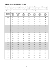
... LEG PRESS (lbs.) 18 38 58 78 98 118 138 158 178 198 218 239 259 279 299 319 339 359 379 399 23 The other numbers refer to the 10 lb. The butterfly arm resistance listed is the resistance for each weight station may vary due to differences in individual weight plates, as well as friction between the cables, pulleys...
... LEG PRESS (lbs.) 18 38 58 78 98 118 138 158 178 198 218 239 259 279 299 319 339 359 379 399 23 The other numbers refer to the 10 lb. The butterfly arm resistance listed is the resistance for each weight station may vary due to differences in individual weight plates, as well as friction between the cables, pulleys...

English Manual
Page 24
...-install it is first used. TIGHTENING THE CABLES Woven cable, the type of cable used on the weight system, can be lifted off the pulleys often, it may have become twisted. Slack can stretch slightly when it . If the cables are over tighten the cables. If a cable tends to slip off the weight stack. If the cables need to the center of Adjustable Pulley Plates (23) can be tightened. Either set...
...-install it is first used. TIGHTENING THE CABLES Woven cable, the type of cable used on the weight system, can be lifted off the pulleys often, it may have become twisted. Slack can stretch slightly when it . If the cables are over tighten the cables. If a cable tends to slip off the weight stack. If the cables need to the center of Adjustable Pulley Plates (23) can be tightened. Either set...

English Manual
Page 25
... and the next page show the proper route for each Cable have not been correctly routed, the weight system will not function properly and damage may occur. The numbers show the proper routing of each Cable. Leg Press Cable (75) 6 9 10 11-Press Upright 7 5 3 2 8 4 Ab Cable (47) 2 4 5 1-High Pulley 1-Press Upright Butterfly Cable (73) 4 5-Left Arm 2 3 1-Right Arm 6-Ab Pulley 3 25 Use the diagrams to be sure that the Cables have been assembled correctly.
... and the next page show the proper route for each Cable have not been correctly routed, the weight system will not function properly and damage may occur. The numbers show the proper routing of each Cable. Leg Press Cable (75) 6 9 10 11-Press Upright 7 5 3 2 8 4 Ab Cable (47) 2 4 5 1-High Pulley 1-Press Upright Butterfly Cable (73) 4 5-Left Arm 2 3 1-Right Arm 6-Ab Pulley 3 25 Use the diagrams to be sure that the Cables have been assembled correctly.

English Manual
Page 30
... Carriage Bolt 93 1 Workout Decal 94 2 Support Plate 95 1 Plastic Weight Cover 96 4 5/16" x 2 3/4" Bolt 97 1 1/2" x 3/4" Spacer 98 1 3/8" x 1 1/4" Button Head Bolt 99 2 5/8" x 1/2" Spacer 100 1 1/2" Plain Nut 101 4 2" Round Inner Cap 102 11 3/8" x 3 3/4" Bolt 103 4 5/8" x 1" Bushing 104 1 Rounded Support Plate 105 2 5/16" Nylon Jamnut # 1 User's Manual # 1 Exercise Guide Note: "#" indicates a non-illustrated part. PART LIST-Model No. PFSY59001 R0402A Key No. Qty. Specifications are subject to change without notice. Description Key No.
... Carriage Bolt 93 1 Workout Decal 94 2 Support Plate 95 1 Plastic Weight Cover 96 4 5/16" x 2 3/4" Bolt 97 1 1/2" x 3/4" Spacer 98 1 3/8" x 1 1/4" Button Head Bolt 99 2 5/8" x 1/2" Spacer 100 1 1/2" Plain Nut 101 4 2" Round Inner Cap 102 11 3/8" x 3 3/4" Bolt 103 4 5/8" x 1" Bushing 104 1 Rounded Support Plate 105 2 5/16" Nylon Jamnut # 1 User's Manual # 1 Exercise Guide Note: "#" indicates a non-illustrated part. PART LIST-Model No. PFSY59001 R0402A Key No. Qty. Specifications are subject to change without notice. Description Key No.
English Manual
Page 32
... implied warranty lasts. This warranty gives you . To help us assist you . The SERIAL NUMBER of the product (see the PART LIST and EXPLODED DRAWING attached at one of its authorized service centers. The KEY NUMBER and DESCRIPTION of the part(s) (see the front cover of whatsoever nature. Mountain Time (excluding holidays). Accordingly, the above is in Canada © 2002 ICON Health & Fitness, Inc. ICON HEALTH & FITNESS, INC...
... implied warranty lasts. This warranty gives you . To help us assist you . The SERIAL NUMBER of the product (see the PART LIST and EXPLODED DRAWING attached at one of its authorized service centers. The KEY NUMBER and DESCRIPTION of the part(s) (see the front cover of whatsoever nature. Mountain Time (excluding holidays). Accordingly, the above is in Canada © 2002 ICON Health & Fitness, Inc. ICON HEALTH & FITNESS, INC...


