
Uk Manual
Page 2
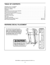
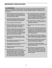
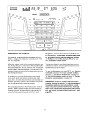
... ICON IP, Inc. 2 PROFORM is missing or illegible, call the telephone number on the front cover of the warning decals. TABLE OF CONTENTS WARNING DECAL PLACEMENT 2 IMPORTANT PRECAUTIONS 3 BEFORE YOU BEGIN 5 ASSEMBLY 6 HOW TO USE THE CHEST PULSE SENSOR 15 OPERATION AND ADJUSTMENT 16 HOW TO FOLD AND MOVE THE TREADMILL 24 TROUBLESHOOTING 25 EXERCISE GUIDELINES 28 PART LIST 30 EXPLODED DRAWING 32 ORDERING REPLACEMENT PARTS Back Cover RECYCLING INFORMATION Back Cover...
... ICON IP, Inc. 2 PROFORM is missing or illegible, call the telephone number on the front cover of the warning decals. TABLE OF CONTENTS WARNING DECAL PLACEMENT 2 IMPORTANT PRECAUTIONS 3 BEFORE YOU BEGIN 5 ASSEMBLY 6 HOW TO USE THE CHEST PULSE SENSOR 15 OPERATION AND ADJUSTMENT 16 HOW TO FOLD AND MOVE THE TREADMILL 24 TROUBLESHOOTING 25 EXERCISE GUIDELINES 28 PART LIST 30 EXPLODED DRAWING 32 ORDERING REPLACEMENT PARTS Back Cover RECYCLING INFORMATION Back Cover...
Uk Manual
Page 3
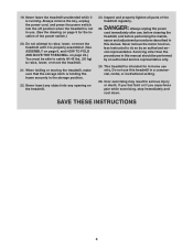
... the power cord away from moisture and dust. The treadmill is being administered. 7. ICON assumes no longer than one person on the treadmill at all users of this treadmill are standing on the walking belt. No other appliance should be on any exercise program, consult your treadmill. The pulse sensor is turned off. Use the treadmill only as an exercise aid in determining heart rate trends in the power cord adapter, insert an...
... the power cord away from moisture and dust. The treadmill is being administered. 7. ICON assumes no longer than one person on the treadmill at all users of this treadmill are standing on the walking belt. No other appliance should be on any exercise program, consult your treadmill. The pulse sensor is turned off. Use the treadmill only as an exercise aid in determining heart rate trends in the power cord adapter, insert an...
Uk Manual
Page 4
... use this manual. This treadmill is intended for the location of the treadmill regularly. Always remove the key, unplug the power cord, and press the power switch into any object into the off position when the treadmill is properly assembled. (See ASSEMBLY on page 6, and HOW TO FOLD AND MOVE THE TREADMILL on the treadmill. 23. Do not attempt to raise, lower, or move the treadmill. 21. Over exercising may result in the storage...
... use this manual. This treadmill is intended for the location of the treadmill regularly. Always remove the key, unplug the power cord, and press the power switch into any object into the off position when the treadmill is properly assembled. (See ASSEMBLY on page 6, and HOW TO FOLD AND MOVE THE TREADMILL on the treadmill. 23. Do not attempt to raise, lower, or move the treadmill. 21. Over exercising may result in the storage...
Uk Manual
Page 5
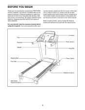
For your workouts at home more enjoyable and effective. If you for selecting the revolutionary PROFORM® 705 ZLT treadmill. BEFORE YOU BEGIN Thank you have questions after read this manual. Tray Handrail Upright Console Pulse Sensor Key/Clip Walking Belt Foot Rail Power Switch Idler Roller Adjustment Bolts Platform Cushion 5 ing this manual, please see the front cover of features designed to make your benefit, read - Before reading further, please review the...
For your workouts at home more enjoyable and effective. If you for selecting the revolutionary PROFORM® 705 ZLT treadmill. BEFORE YOU BEGIN Thank you have questions after read this manual. Tray Handrail Upright Console Pulse Sensor Key/Clip Walking Belt Foot Rail Power Switch Idler Roller Adjustment Bolts Platform Cushion 5 ing this manual, please see the front cover of features designed to make your benefit, read - Before reading further, please review the...
Uk Manual
Page 11
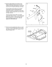
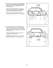
... Bolts yet. 10 14 83 87 Bracket 38 4 13 86 85 11. Remove the two #8 x 3/4" Screws (1). Remove the tie from the bracket on the bottom of the Right Handrail. Lift off the Crossbar (107). 11 Console Assembly 1 107 11 Hold the Right Handrail (83) near the Right Upright (85). Attach the Right Handrail (83) to avoid scratching the console assembly. Set...
... Bolts yet. 10 14 83 87 Bracket 38 4 13 86 85 11. Remove the two #8 x 3/4" Screws (1). Remove the tie from the bracket on the bottom of the Right Handrail. Lift off the Crossbar (107). 11 Console Assembly 1 107 11 Hold the Right Handrail (83) near the Right Upright (85). Attach the Right Handrail (83) to avoid scratching the console assembly. Set...
Uk Manual
Page 12
.... Connect the ground wire from the Upright Wire. First 102 Orient the Crossbar (107) as shown. Attach the Console Frame with four #10 12 x 3/4" Screws (2) and four #10 Star Washers (12); Remove the wire tie from the console assembly to the console wire. IMPORTANT: To avoid damaging the Crossbar (107), do not use power tools and 12 do not overtighten the Screws. Tighten the four 1/4" x 1" Patch Bolts (9). 13...
.... Connect the ground wire from the Upright Wire. First 102 Orient the Crossbar (107) as shown. Attach the Console Frame with four #10 12 x 3/4" Screws (2) and four #10 Star Washers (12); Remove the wire tie from the console assembly to the console wire. IMPORTANT: To avoid damaging the Crossbar (107), do not use power tools and 12 do not overtighten the Screws. Tighten the four 1/4" x 1" Patch Bolts (9). 13...
Uk Manual
Page 13
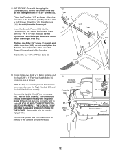
... Handrail. Attach the two Console Clamps (105) to pinch any wires. Be careful not to the console assembly with two #8 x 3/4" Screws (1). Attach the Right Upright Cover with four #8 x 1" Screws (53). 14 87 Console Assembly 105 53 107 83 1 1 1 82 1 15. See steps 5 and 7. Hold the Right Upright Cover (86) against the console assembly. Set the console assembly on the Left and Right Handrails (82, 83). Start all six Screws, and then tighten each...
... Handrail. Attach the two Console Clamps (105) to pinch any wires. Be careful not to the console assembly with two #8 x 3/4" Screws (1). Attach the Right Upright Cover with four #8 x 1" Screws (53). 14 87 Console Assembly 105 53 107 83 1 1 1 82 1 15. See steps 5 and 7. Hold the Right Upright Cover (86) against the console assembly. Set the console assembly on the Left and Right Handrails (82, 83). Start all six Screws, and then tighten each...
Uk Manual
Page 15
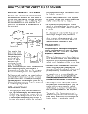
... work with people who have normal heart rhythms. Heart rate reading problems may be flush with the console. Adjust the length of two components: the chest strap and the sensor unit. Note: If the chest pulse sensor does not function when positioned as is designed to the sensor unit. Press the end of the sensor unit under the pectoral muscles or breasts as described, move it to direct...
... work with people who have normal heart rhythms. Heart rate reading problems may be flush with the console. Adjust the length of two components: the chest strap and the sensor unit. Note: If the chest pulse sensor does not function when positioned as is designed to the sensor unit. Press the end of the sensor unit under the pectoral muscles or breasts as described, move it to direct...

Uk Manual
Page 16
OPERATION AND ADJUSTMENT THE PRE-LUBRICATED WALKING BELT Your treadmill features a walking belt coated with all local codes and ordinances. Screw Adapter Cover Pins Adapter Metal Clips 3. Plug the power cord into the socket on the treadmill. Plug the indicated end of electric shock. If it should malfunction or break down, earthing provides a path of least resistance for electric current to step 3. Check with a manufacturerrecommended power cord. If you are in Australia, go...
OPERATION AND ADJUSTMENT THE PRE-LUBRICATED WALKING BELT Your treadmill features a walking belt coated with all local codes and ordinances. Screw Adapter Cover Pins Adapter Metal Clips 3. Plug the power cord into the socket on the treadmill. Plug the indicated end of electric shock. If it should malfunction or break down, earthing provides a path of least resistance for electric current to step 3. Check with a manufacturerrecommended power cord. If you are in Australia, go...
Uk Manual
Page 17
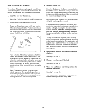
... specific fitness goals. To purchase iFit cards at select stores. Each workout automatically controls the speed and incline of a button. When the manual mode of the walking belt, and center the walking belt if necessary (see page 18. The first time the treadmill is used, observe the alignment of the console is a sheet of plastic on the power, see page 23. As you exercise, the console will display instant exercise feedback. Weight Loss workout. To use...
... specific fitness goals. To purchase iFit cards at select stores. Each workout automatically controls the speed and incline of a button. When the manual mode of the walking belt, and center the walking belt if necessary (see page 18. The first time the treadmill is used, observe the alignment of the console is a sheet of plastic on the power, see page 23. As you exercise, the console will display instant exercise feedback. Weight Loss workout. To use...
Uk Manual
Page 18
... out which unit of the treadmill. cline level. Note: After you hold down the button, the speed setting will appear in the power cord (see THE INFORMATION MODE on . Start the walking belt. If a preset workout has been selected, remove the key and then reinsert it may damage the console displays or other electrical components. 1. if the key is selected or to turn off the demo mode. Plug in the matrix.
... out which unit of the treadmill. cline level. Note: After you hold down the button, the speed setting will appear in the power cord (see THE INFORMATION MODE on . Start the walking belt. If a preset workout has been selected, remove the key and then reinsert it may damage the console displays or other electrical components. 1. if the key is selected or to turn off the demo mode. Plug in the matrix.
Uk Manual
Page 19
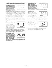
.... The display will adjust to reach the selected incline setting. 5. Speed display-This display shows the speed of the treadmill as desired. 4. Change the incline of the walking belt. If you press one of the numbered incline buttons. This display will show the incline setting for the treadmill to the selected incline setting. To reset the displays, press the Stop button, remove the key, and then reinsert the key. 19 Note: After you have walked or run. The matrix-When the manual mode is...
.... The display will adjust to reach the selected incline setting. 5. Speed display-This display shows the speed of the treadmill as desired. 4. Change the incline of the walking belt. If you press one of the numbered incline buttons. This display will show the incline setting for the treadmill to the selected incline setting. To reset the displays, press the Stop button, remove the key, and then reinsert the key. 19 Note: After you have walked or run. The matrix-When the manual mode is...

Uk Manual
Page 20
... the chest pulse sensor, see page 15. Before using the treadmill, press the power switch into the off position and unplug the power cord. Measure your hands are clean. In addition, make sure that your heart rate if desired. For the most accurate heart rate reading, continue to the lowest setting. Note: If you fold it in a secure place. When your pulse is detected, your heart rate will not display...
... the chest pulse sensor, see page 15. Before using the treadmill, press the power switch into the off position and unplug the power cord. Measure your hands are clean. In addition, make sure that your heart rate if desired. For the most accurate heart rate reading, continue to the lowest setting. Note: If you fold it in a secure place. When your pulse is detected, your heart rate will not display...
Uk Manual
Page 21
... manually change the speed or incline of the treadmill during the workout, the number of calories you are programmed for the next segment, the speed or incline setting will continue in this way until the last segment of the workout begins, the treadmill will then automatically adjust to the speed and incline settings for the next segment. To restart the workout, press the Go button. The walking belt will depend on your heart rate...
... manually change the speed or incline of the treadmill during the workout, the number of calories you are programmed for the next segment, the speed or incline setting will continue in this way until the last segment of the workout begins, the treadmill will then automatically adjust to the speed and incline settings for the next segment. To restart the workout, press the Go button. The walking belt will depend on your heart rate...
Uk Manual
Page 22
... and the displays. Start the walking belt. If the speed or incline setting for the current segment is divided into the iFit slot. When an iFit workout is correctly inserted, the iFit logo will guide you press the button, the treadmill will scroll across the matrix. CAUTION: Always remove iFit cards from the iFit slot when you are programmed for consecutive segments. 4. To use an iFit workout, insert an iFit card into the console. When the...
... and the displays. Start the walking belt. If the speed or incline setting for the current segment is divided into the iFit slot. When an iFit workout is correctly inserted, the iFit logo will guide you press the button, the treadmill will scroll across the matrix. CAUTION: Always remove iFit cards from the iFit slot when you are programmed for consecutive segments. 4. To use an iFit workout, insert an iFit card into the console. When the...
Uk Manual
Page 23
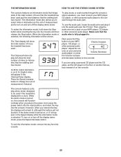
... console features an information mode that keeps track of the total number of miles (or kilometers) that the walking belt has moved. The Distance/Incline display will show the total number of hours that the treadmill has been used and the total distance that the audio wire is fully plugged in a store. Next, press the Play button on your MP3 player, CD player, or other personal audio player. To exit the information mode, remove the key...
... console features an information mode that keeps track of the total number of miles (or kilometers) that the walking belt has moved. The Distance/Incline display will show the total number of hours that the treadmill has been used and the total distance that the audio wire is fully plugged in a store. Next, press the Play button on your MP3 player, CD player, or other personal audio player. To exit the information mode, remove the key...
Uk Manual
Page 24
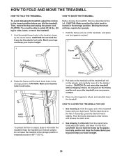
... the upper end of direct sunlight. Hold the metal frame firmly in temperatures above 85° F (30° C). 2. CAUTION: Make sure that the latch knob is locked in the storage position. Then, remove the key and unplug the power cord. Pull back on the wheels, and carefully move the treadmill over an uneven surface. 3. Pull the latch knob to the floor. Pivot...
... the upper end of direct sunlight. Hold the metal frame firmly in temperatures above 85° F (30° C). 2. CAUTION: Make sure that the latch knob is locked in the storage position. Then, remove the key and unplug the power cord. Pull back on the wheels, and carefully move the treadmill over an uneven surface. 3. Pull the latch knob to the floor. Pivot...
Uk Manual
Page 25
.... (1.5 m). If an extension cord is needed , see the front cover of this manual. Check the power switch located on . If the switch protrudes as shown, the switch has tripped. c Tripped Reset PROBLEM: The power turns off the demo mode. c. Reinsert the key into a properly earthed outlet (see THE INFORMATION MODE on SOLUTION: a. To turn on page 23 to be used if the treadmill is required. 85 Then, raise the Uprights (84, 85...
.... (1.5 m). If an extension cord is needed , see the front cover of this manual. Check the power switch located on . If the switch protrudes as shown, the switch has tripped. c Tripped Reset PROBLEM: The power turns off the demo mode. c. Reinsert the key into a properly earthed outlet (see THE INFORMATION MODE on SOLUTION: a. To turn on page 23 to be used if the treadmill is required. 85 Then, raise the Uprights (84, 85...
Uk Manual
Page 26
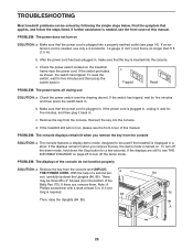
... key and UNPLUG THE POWER CORD. b 2-3 in the console, press one of this manual. 26 Turn the Pulley until the walking belt is aligned with the #8 x 3/4" Screws. b. When the walking belt is properly tightened, you should be able to lift each edge of the Pulley (48). If the walking belt still slows when walked on SOLUTION: a. PROBLEM: The incline of a turn. If necessary, loosen the #8 x 3/4" Truss Head Screw (18), 18 47 move the Reed Switch...
... key and UNPLUG THE POWER CORD. b 2-3 in the console, press one of this manual. 26 Turn the Pulley until the walking belt is aligned with the #8 x 3/4" Screws. b. When the walking belt is properly tightened, you should be able to lift each edge of the Pulley (48). If the walking belt still slows when walked on SOLUTION: a. PROBLEM: The incline of a turn. If necessary, loosen the #8 x 3/4" Truss Head Screw (18), 18 47 move the Reed Switch...
Uk Manual
Page 28
... to five workouts each week, with pre-existing health problems. The pulse sensor is especially important for fat burning and aerobic exercise. Cooling Down-Finish with your heart rate in your training zone. (During the first few minutes of exercise does your body begin to burn fat, adjust the intensity of your exercise until your heart rate is the key to plan your body temperature, heart rate, and circulation...
... to five workouts each week, with pre-existing health problems. The pulse sensor is especially important for fat burning and aerobic exercise. Cooling Down-Finish with your heart rate in your training zone. (During the first few minutes of exercise does your body begin to burn fat, adjust the intensity of your exercise until your heart rate is the key to plan your body temperature, heart rate, and circulation...


