

User Manual
Page 2
TABLE OF CONTENTS IMPORTANT PRECAUTIONS 3 BEFORE YOU BEGIN 5 ASSEMBLY 6 OPERATION AND ADJUSTMENT 9 HOW TO FOLD AND MOVE THE TREADMILL 15 TROUBLESHOOTING 17 CONDITIONING GUIDELINES 19 PART LIST 22 ORDERING REPLACEMENT PARTS Back Cover LIMITED WARRANTY Back Cover Note: An EXPLODED DRAWING is a registered trademark of this manual. PROFORM is attached in the center of ICON Health & Fitness, Inc. 2
TABLE OF CONTENTS IMPORTANT PRECAUTIONS 3 BEFORE YOU BEGIN 5 ASSEMBLY 6 OPERATION AND ADJUSTMENT 9 HOW TO FOLD AND MOVE THE TREADMILL 15 TROUBLESHOOTING 17 CONDITIONING GUIDELINES 19 PART LIST 22 ORDERING REPLACEMENT PARTS Back Cover LIMITED WARRANTY Back Cover Note: An EXPLODED DRAWING is a registered trademark of this manual. PROFORM is attached in the center of ICON Health & Fitness, Inc. 2
User Manual
Page 3
... power is turned off position when the treadmill is properly assembled. (See ASSEMBLY on page 6, and HOW TO FOLD AND MOVE THE TREADMILL on page 5 if the treadmill is capable of high speeds. Wear appropriate exercise clothing when using the treadmill. 16. Do not wear loose clothing ...that meets all times. 12. When connecting the power cord (see your local PROFORM...
... power is turned off position when the treadmill is properly assembled. (See ASSEMBLY on page 6, and HOW TO FOLD AND MOVE THE TREADMILL on page 5 if the treadmill is capable of high speeds. Wear appropriate exercise clothing when using the treadmill. 16. Do not wear loose clothing ...that meets all times. 12. When connecting the power cord (see your local PROFORM...
User Manual
Page 6
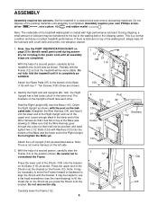
...Brackets 122 123 124 3 12 Clip 105 105 34 115 Set the treadmill in the power cord until assembly is lubricant on the Shock as described above. Do not dispose of a second person,... carefully tip the treadmill onto its left side. 3. the Right Upright ...Harness goes through the cutout so that it lies flat on page 23 to identify small parts used during assembly. Partially fold the Frame (12) so that it will be pinched, and hand tighten two 2 1/2"...
...Brackets 122 123 124 3 12 Clip 105 105 34 115 Set the treadmill in the power cord until assembly is lubricant on the Shock as described above. Do not dispose of a second person,... carefully tip the treadmill onto its left side. 3. the Right Upright ...Harness goes through the cutout so that it lies flat on page 23 to identify small parts used during assembly. Partially fold the Frame (12) so that it will be pinched, and hand tighten two 2 1/2"...
User Manual
Page 7
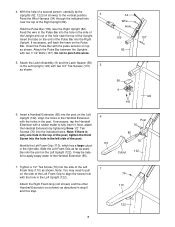
... in the right side. Slide the Left Foam Grip as far as shown. 34 Wire Hole 109 107 82 56 9 122 101 6. Attach the Latch Assembly (9) and the Latch Spacer (56) to the Left Upright (122) with the pulse sensors on the Pulse Bar. Tighten a 1/2" Tek Screw (76) into the side...
... in the right side. Slide the Left Foam Grip as far as shown. 34 Wire Hole 109 107 82 56 9 122 101 6. Attach the Latch Assembly (9) and the Latch Spacer (56) to the Left Upright (122) with the pulse sensors on the Pulse Bar. Tighten a 1/2" Tek Screw (76) into the side...
User Manual
Page 8
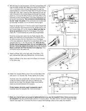
...) with four 1 1/4" Tek Screws (79). Make sure that all four Screws before you lower the Uprights. Make sure that no wires are under the treadmill. 8 Press an Upright Cap (117) into the Right Upright (82). Securely tighten the plastic tie on the Console Base in a secure place. Attach the... Attach a Wheel to place your foot on top of each Upright (82, 122 [not shown]). Make sure that there is enough slack in assembly step 2. Note: Extra screws may be included. Connect the Wire Harness and Pulse Wire to the connector on the Console Base to the wire from...
...) with four 1 1/4" Tek Screws (79). Make sure that all four Screws before you lower the Uprights. Make sure that no wires are under the treadmill. 8 Press an Upright Cap (117) into the Right Upright (82). Securely tighten the plastic tie on the Console Base in a secure place. Attach the... Attach a Wheel to place your foot on top of each Upright (82, 122 [not shown]). Make sure that there is enough slack in assembly step 2. Note: Extra screws may be included. Connect the Wire Harness and Pulse Wire to the connector on the Console Base to the wire from...
User Manual
Page 22
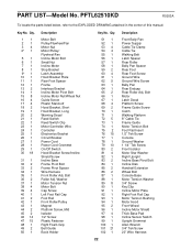
... 48 1 49 2 50 1 Description Motor Belt Pulley/Flywheel/Fan Motor Nut Motor/Pulley/ Flywheel/Fan Incline Motor Bolt Small Nut Incline Motor Stop Bracket Latch Assembly Hood Bracket Plate Rear Foot Spacer Frame Interface Bracket Incline Motor Pivot Bolt Incline Motor Nut/Wheel Nut Guide Screw Plastic Stand-off Hood Bracket...
... 48 1 49 2 50 1 Description Motor Belt Pulley/Flywheel/Fan Motor Nut Motor/Pulley/ Flywheel/Fan Incline Motor Bolt Small Nut Incline Motor Stop Bracket Latch Assembly Hood Bracket Plate Rear Foot Spacer Frame Interface Bracket Incline Motor Pivot Bolt Incline Motor Nut/Wheel Nut Guide Screw Plastic Stand-off Hood Bracket...
User Manual
Page 23
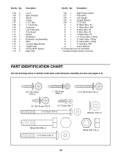
... Description U-nut Base Endcap Shock Choke 3 1/2" Bolt 1" Tek Screw Pulse Bar Left Foam Grip Trim Guard Shield Small Bolt Extension Leg Assembly Base Console Base Bottom Upright Cap Incline Motor Spacer Base Pad Key No. Description 120 1 Right Frame Guide 121 1 Pulse Wire 122 ... parts are not illustrated * Includes all parts shown in the box PART IDENTIFICATION CHART Use the drawings below to identify small parts used during the assembly process (see pages 6-9). 3/4" Tek Screw (101)-2 1" Tek Screw (108)-4 1 1/4" Tek Screw (79)-4 1/2" Tek Screw (76)-8 1/2" Screw (46)-7 3 1/2" ...
... Description U-nut Base Endcap Shock Choke 3 1/2" Bolt 1" Tek Screw Pulse Bar Left Foam Grip Trim Guard Shield Small Bolt Extension Leg Assembly Base Console Base Bottom Upright Cap Incline Motor Spacer Base Pad Key No. Description 120 1 Right Frame Guide 121 1 Pulse Wire 122 ... parts are not illustrated * Includes all parts shown in the box PART IDENTIFICATION CHART Use the drawings below to identify small parts used during the assembly process (see pages 6-9). 3/4" Tek Screw (101)-2 1" Tek Screw (108)-4 1 1/4" Tek Screw (79)-4 1/2" Tek Screw (76)-8 1/2" Screw (46)-7 3 1/2" ...


