

English Manual
Page 2
... decal(s) may not be shown at actual size. PROFORM is missing or illegible, see the front cover of this manual and request a free replacement decal. TABLE OF CONTENTS WARNING DECAL PLACEMENT 2 IMPORTANT PRECAUTIONS 3 BEFORE YOU BEGIN 4 PART IDENTIFICATION CHART 5 ASSEMBLY 6 HOW TO USE THE ELLIPTICAL 16 FCC INFORMATION 28 MAINTENANCE AND TROUBLESHOOTING 29...
... decal(s) may not be shown at actual size. PROFORM is missing or illegible, see the front cover of this manual and request a free replacement decal. TABLE OF CONTENTS WARNING DECAL PLACEMENT 2 IMPORTANT PRECAUTIONS 3 BEFORE YOU BEGIN 4 PART IDENTIFICATION CHART 5 ASSEMBLY 6 HOW TO USE THE ELLIPTICAL 16 FCC INFORMATION 28 MAINTENANCE AND TROUBLESHOOTING 29...

English Manual
Page 5
... Washer (131)–-8 M8 x 25mm x 1.5mm Washer (126)–-4 M17 x 27mm Wave Washer (88)–-4 M8 Locknut (105)–-6 M4 x 16mm Screw (93)–-14 M6 x 12mm Screw (139)–-8 M6 x 50mm Screw (62)–-2 M8 x 16mm Screw (102)–-12 M8 x 25mm Screw (128)–-2 M8 x 45mm Bolt ...(104)–-6 M10 x 120mm Screw (100)–-4 5 The number in the hardware kit, check to identify the small parts needed for assembly. Extra parts may be included. PART IDENTIFICATION CHART Use the drawings below each drawing is the key number of the part, from the PART LIST...
... Washer (131)–-8 M8 x 25mm x 1.5mm Washer (126)–-4 M17 x 27mm Wave Washer (88)–-4 M8 Locknut (105)–-6 M4 x 16mm Screw (93)–-14 M6 x 12mm Screw (139)–-8 M6 x 50mm Screw (62)–-2 M8 x 16mm Screw (102)–-12 M8 x 25mm Screw (128)–-2 M8 x 45mm Bolt ...(104)–-6 M10 x 120mm Screw (100)–-4 5 The number in the hardware kit, check to identify the small parts needed for assembly. Extra parts may be included. PART IDENTIFICATION CHART Use the drawings below each drawing is the key number of the part, from the PART LIST...

English Manual
Page 6
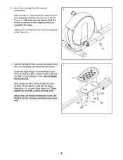
..., go to http://productvideo.co/ assembly/proform or use power tools. 1. While a second person lifts the Folding Frame (2), attach the Rear Stabilizer (4) to the floor. 4 100 Handle 67 2 6 Note: If the elliptical is in a cleared area and remove the packing materials. Note: The Folding Frame may be ...easier if you nish all parts in the folded position, unfold it after completing this step. To unfold the elliptical, hold the handle on the Rear Stabilizer (4), press the Latch Button (67), and lower the Rear Stabilizer and the Folding Frame (2) to...
..., go to http://productvideo.co/ assembly/proform or use power tools. 1. While a second person lifts the Folding Frame (2), attach the Rear Stabilizer (4) to the floor. 4 100 Handle 67 2 6 Note: If the elliptical is in a cleared area and remove the packing materials. Note: The Folding Frame may be ...easier if you nish all parts in the folded position, unfold it after completing this step. To unfold the elliptical, hold the handle on the Rear Stabilizer (4), press the Latch Button (67), and lower the Rear Stabilizer and the Folding Frame (2) to...

English Manual
Page 8
... inside the hexagonal holes. Slide an M17 x 27mm Wave Washer (88) onto each end of the Upright Axle. Tip: Avoid damaging the Upright Wire (60). Assemble the Left Upper Body Arm (9) and the Left Upper Body Leg (7) in the same way. 9 104 105 7 8 104 105 104 Hexagonal Holes 6 5. Do not fully...
... inside the hexagonal holes. Slide an M17 x 27mm Wave Washer (88) onto each end of the Upright Axle. Tip: Avoid damaging the Upright Wire (60). Assemble the Left Upper Body Arm (9) and the Left Upper Body Leg (7) in the same way. 9 104 105 7 8 104 105 104 Hexagonal Holes 6 5. Do not fully...
English Manual
Page 9
do not tighten the Screws yet. Identify the Right Pedal (14) and the Right Pedal Arm (12) assembly and orient them as shown. 7 Attach the Right Pedal (14) to the Left Pedal Arm (not shown) assembly in the same way. 14 12 140 139 140 139 140 62 9 Attach the Left Pedal (not shown) to the... to prevent it from tipping while you complete this step. 1 Tighten the Leveling Foot (41) into the Right Pedal Arm (12) and the Right Pedal (14). 6.
do not tighten the Screws yet. Identify the Right Pedal (14) and the Right Pedal Arm (12) assembly and orient them as shown. 7 Attach the Right Pedal (14) to the Left Pedal Arm (not shown) assembly in the same way. 14 12 140 139 140 139 140 62 9 Attach the Left Pedal (not shown) to the... to prevent it from tipping while you complete this step. 1 Tighten the Leveling Foot (41) into the Right Pedal Arm (12) and the Right Pedal (14). 6.
English Manual
Page 35
Description 101 1 102 20 103 2 104 6 105 6 106 12 107 4 108 4 109 1 110 2 111 6 112 2 113 2 114 2 115 2 116 4 117 2 118 2 119 2 120 14 121 2 122 1 123 2 124 4 125 1 Anchored Zip Tie M8 x 16mm Screw M10 Locknut M8 x 45mm Bolt M8 Locknut Link Arm Bushing M10 x 25mm Screw M10 ...Washer Frame Wire M8 x 23.5mm x 1mm Washer Pivot Axle Cover M8 Washer Crank Axle Cover Magnet Assembly Pedal Arm Snap Ring Long Latch Spring Latch Latch Spring Medium Snap Ring Mushroom Fastener/Screw Latch Insert 3/8" x 1/2" Flange Screw Latch Housing M4 x 42mm Screw...
Description 101 1 102 20 103 2 104 6 105 6 106 12 107 4 108 4 109 1 110 2 111 6 112 2 113 2 114 2 115 2 116 4 117 2 118 2 119 2 120 14 121 2 122 1 123 2 124 4 125 1 Anchored Zip Tie M8 x 16mm Screw M10 Locknut M8 x 45mm Bolt M8 Locknut Link Arm Bushing M10 x 25mm Screw M10 ...Washer Frame Wire M8 x 23.5mm x 1mm Washer Pivot Axle Cover M8 Washer Crank Axle Cover Magnet Assembly Pedal Arm Snap Ring Long Latch Spring Latch Latch Spring Medium Snap Ring Mushroom Fastener/Screw Latch Insert 3/8" x 1/2" Flange Screw Latch Housing M4 x 42mm Screw...


