Service Manual
Page 1
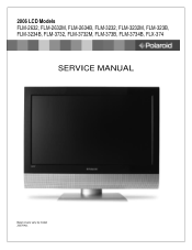
2006 LCD Models FLM-2632, FLM-2632M, FLM-2634B, FLM-3232, FLM-3232M, FLM-323B, FLM-3234B, FLM-3732, FLM-3732M, FLM-373B, FLM-3734B, FLX-374 SERVICE MANUAL Bezel covers vary by model 20070411
2006 LCD Models FLM-2632, FLM-2632M, FLM-2634B, FLM-3232, FLM-3232M, FLM-323B, FLM-3234B, FLM-3732, FLM-3732M, FLM-373B, FLM-3734B, FLX-374 SERVICE MANUAL Bezel covers vary by model 20070411
Service Manual
Page 3
...use lead-free solder (Sn-Ag-Cu). Sn e4 - contains Bi e7 - Look at the markings on the component. Before servicing the TV, follow these service guidelines: ELECTRIC SHOCK HAZARD Always disconnect AC power before touching any surface. • Wear a grounding wrist strap (available at...matches the symbol on board and components within this time. ELECTROSTATIC DISCHARGE (ESD) Components inside of antistatic bags because only the inside an LCD or plasma TV are ready to static electricity. Never insert any circuit! Precious metal (e.g., Ag, Au, NiPd, NiPdAu) (no Bi) e6 - ...
...use lead-free solder (Sn-Ag-Cu). Sn e4 - contains Bi e7 - Look at the markings on the component. Before servicing the TV, follow these service guidelines: ELECTRIC SHOCK HAZARD Always disconnect AC power before touching any surface. • Wear a grounding wrist strap (available at...matches the symbol on board and components within this time. ELECTROSTATIC DISCHARGE (ESD) Components inside of antistatic bags because only the inside an LCD or plasma TV are ready to static electricity. Never insert any circuit! Precious metal (e.g., Ag, Au, NiPd, NiPdAu) (no Bi) e6 - ...

Service Manual
Page 4
... different types of solder. Leaving the bit in contact with steel wool or fine sandpaper. (0) NOTICE ABOUT REPLACEMENT PARTS Many electrical and mechanical parts within LCD or plasma televisions are chosen for their specific safety characteristics within the overall system. (1) Always use a dedicated soldering bit for an extended period may damage...
... different types of solder. Leaving the bit in contact with steel wool or fine sandpaper. (0) NOTICE ABOUT REPLACEMENT PARTS Many electrical and mechanical parts within LCD or plasma televisions are chosen for their specific safety characteristics within the overall system. (1) Always use a dedicated soldering bit for an extended period may damage...
Service Manual
Page 5
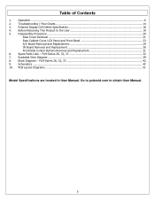
...5 Spare Parts Lists - FLM-Series 26, 32, 37 32 7. PCB Layout Diagrams ...51 Model Specifications are located in User Manual. FLM-Series 26, 32, 37 42 9. Disassembly Procedure...20 Rear Cover Removal ...21 Rear Cabinet Cover LCD Panel and Front Bezel 23 ...A/V Board Removal and Replacement 29 IR Board Removal and Replacement 30 Front/Side Control Buttons Removal and Replacement 31 6. Exploded View Diagram ...39 8. Block Diagram - Polaroid...
...5 Spare Parts Lists - FLM-Series 26, 32, 37 32 7. PCB Layout Diagrams ...51 Model Specifications are located in User Manual. FLM-Series 26, 32, 37 42 9. Disassembly Procedure...20 Rear Cover Removal ...21 Rear Cabinet Cover LCD Panel and Front Bezel 23 ...A/V Board Removal and Replacement 29 IR Board Removal and Replacement 30 Front/Side Control Buttons Removal and Replacement 31 6. Exploded View Diagram ...39 8. Block Diagram - Polaroid...
Service Manual
Page 18
These defective cells can be controlled. 3. Polaroid Display Cell Defect Specification In some cases, a panel may have defective cells that cannot be categorized into two types; (1) Non-lighting or dark cell defect: ...defect in which the cell is always off (2) Non-extinguishing or bright cell defect: defect in which the cell is always on The Polaroid Display Cell Defect Specifications below define the allowed limits for display cell defects and are used as the criteria in determining whether an...
These defective cells can be controlled. 3. Polaroid Display Cell Defect Specification In some cases, a panel may have defective cells that cannot be categorized into two types; (1) Non-lighting or dark cell defect: ...defect in which the cell is always off (2) Non-extinguishing or bright cell defect: defect in which the cell is always on The Polaroid Display Cell Defect Specifications below define the allowed limits for display cell defects and are used as the criteria in determining whether an...

Service Manual
Page 20
...screws. • To help keep track of screws, place each component's screws next to the component on page 19. When servicing an LCD or plasma TV, always observe the following safety guidelines: • Wear a grounding (ESD) wrist strap, and use them. Note: Before returning this... work surface that is removed from their edges. ELECTROSTATIC DISCHARGE (ESD) Components inside of antistatic bags because only the inside an LCD or plasma TV are ready to static electricity. Never slide components over any surface. • Wear a grounding wrist strap (available at most ...
...screws. • To help keep track of screws, place each component's screws next to the component on page 19. When servicing an LCD or plasma TV, always observe the following safety guidelines: • Wear a grounding (ESD) wrist strap, and use them. Note: Before returning this... work surface that is removed from their edges. ELECTROSTATIC DISCHARGE (ESD) Components inside of antistatic bags because only the inside an LCD or plasma TV are ready to static electricity. Never slide components over any surface. • Wear a grounding wrist strap (available at most ...
Service Manual
Page 21
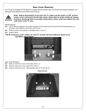
...wall outlet. Allow time for power within all system boards to protect the front bezel and LCD screen from being scratched. Use protective cloth between work bench and TV front. Stand Removal (1) Lay TV flat on workbench. slide toward bottom of any objects into the vent holes in the ... discharge before you begin disassembly. Never insert any part the TV, make sure the power is OFF, and the power cord is a 26" model. 32" and 37" models will have different stand screw quantities and locations. Use protective cloth between work bench and TV front. (2) Remove screws in the...
...wall outlet. Allow time for power within all system boards to protect the front bezel and LCD screen from being scratched. Use protective cloth between work bench and TV front. Stand Removal (1) Lay TV flat on workbench. slide toward bottom of any objects into the vent holes in the ... discharge before you begin disassembly. Never insert any part the TV, make sure the power is OFF, and the power cord is a 26" model. 32" and 37" models will have different stand screw quantities and locations. Use protective cloth between work bench and TV front. (2) Remove screws in the...
Service Manual
Page 22
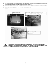
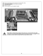
... to the left (PIC3). (8) Tear off the Aluminum foil covering the LVDS connector. There are connected so be careful. Disconnect LVDS cable connector from LCD panel (PIC2). (9) Disconnect the LCD Panel power cord from the A/V connector side (PIC1). Release control box from back hinges and tilt to the User, on page 19.
... to the left (PIC3). (8) Tear off the Aluminum foil covering the LVDS connector. There are connected so be careful. Disconnect LVDS cable connector from LCD panel (PIC2). (9) Disconnect the LCD Panel power cord from the A/V connector side (PIC1). Release control box from back hinges and tilt to the User, on page 19.
Service Manual
Page 23
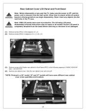
... power is OFF, and the power cord is completely detached from the wall outlet. Note: OEM LCD panels were used in the TV case. Allow time for power within all models. Rear Cabinet Cover LCD Panel and Front Bezel Note: Before disassembly of 2, 3, 4, B, C, D (3) Remove screws... which fasten rear cabinet to front frame (PIC1) in the following LCD panel disassembly/removal instructions may not apply to all system boards to discharge before removing so the bezel is a 26" model. 32" and 37" models will come off. *NOTE: Pictured is not damaged. (1) Remove screws (PIC1...
... power is OFF, and the power cord is completely detached from the wall outlet. Note: OEM LCD panels were used in the TV case. Allow time for power within all models. Rear Cabinet Cover LCD Panel and Front Bezel Note: Before disassembly of 2, 3, 4, B, C, D (3) Remove screws... which fasten rear cabinet to front frame (PIC1) in the following LCD panel disassembly/removal instructions may not apply to all system boards to discharge before removing so the bezel is a 26" model. 32" and 37" models will come off. *NOTE: Pictured is not damaged. (1) Remove screws (PIC1...

Service Manual
Page 25
(8) Remove the EMI Aluminum Foil Sheilding Tape from the LCD Panel (PIC1, 2) (9) EMI Aluminum Foil Sheilding Tape must be replaced during assembly. Remove the EMI Aluminum Foil Shielding Tape which secures the Keyboard wiring to the panel. 25
(8) Remove the EMI Aluminum Foil Sheilding Tape from the LCD Panel (PIC1, 2) (9) EMI Aluminum Foil Sheilding Tape must be replaced during assembly. Remove the EMI Aluminum Foil Shielding Tape which secures the Keyboard wiring to the panel. 25

Service Manual
Page 27
(13) Remove the foam spacer from LCD Panel and remove the A/V wire under the frame (PIC1). (14) Save foam spacer and place in position during assembly. (15) Remove the A/V subassembly from the bezel (PIC2). (16) Remove screws (PIC1) in the sequence: 1-2 (17) Disconnect the LCD Panel cable from the D-SUB board (PIC1) 27
(13) Remove the foam spacer from LCD Panel and remove the A/V wire under the frame (PIC1). (14) Save foam spacer and place in position during assembly. (15) Remove the A/V subassembly from the bezel (PIC2). (16) Remove screws (PIC1) in the sequence: 1-2 (17) Disconnect the LCD Panel cable from the D-SUB board (PIC1) 27
Service Manual
Page 28
This procedure ensures that secure the LCD panel to the User, on page 19. Lift LCD Panel from the bezel (20) Replace LCD panel. (21) The front bezel can now be replaced if needed. Note: Before returning this product to the end user, you must follow the steps outlined in the section, Before Returning This Product to the bezel (PIC1, PIC2) (19) TWO MEN REQUIRED!! (18) Remove screws that the chassis will not cause electric shock. 28
This procedure ensures that secure the LCD panel to the User, on page 19. Lift LCD Panel from the bezel (20) Replace LCD panel. (21) The front bezel can now be replaced if needed. Note: Before returning this product to the end user, you must follow the steps outlined in the section, Before Returning This Product to the bezel (PIC1, PIC2) (19) TWO MEN REQUIRED!! (18) Remove screws that the chassis will not cause electric shock. 28
Service Manual
Page 38
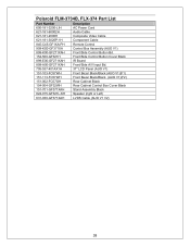
Polaroid FLM-3734B, FLX-374 Part List Part Number Description 600-181-3200-LIH AC Power Cord 621-181-60002H Audio Cable 621-181-2000H Composite Video ... Bd. 154-500-GF321H Front/Side Control Button Cover Black 899-E00-GF271XAH IR Board 899-A00-GF271XAH Front/Side A/V Input Bd. 705-537-401AX1H 37" LCD Panel (AUO V1) 151-103-FC57WH Front Bezel Black/Black (AUO V1)(F1) 151-113-FC57WH Front Bezel Black/Black (AUO V1)(F2) 151-002...
Polaroid FLM-3734B, FLX-374 Part List Part Number Description 600-181-3200-LIH AC Power Cord 621-181-60002H Audio Cable 621-181-2000H Composite Video ... Bd. 154-500-GF321H Front/Side Control Button Cover Black 899-E00-GF271XAH IR Board 899-A00-GF271XAH Front/Side A/V Input Bd. 705-537-401AX1H 37" LCD Panel (AUO V1) 151-103-FC57WH Front Bezel Black/Black (AUO V1)(F1) 151-113-FC57WH Front Bezel Black/Black (AUO V1)(F2) 151-002...


