
Service Manual
Page 4
... is switched off. 2.3 Do not use any adapter that have to the detailed list before replacing components that is not identical with the TV set. Before servicing LCD TV make sure to anti statics. Instructions Be sure to switch off the power supply before the pulling out or plugging in the connection wire... when the module is in operation or just after the power is on the module lest it should result. 2.9 As most of the circuitry in LCD TV set is composed of CMOS integrated circuits, it will cause fire or damage to the set. 2.4 Never operate the set please take reference with the...
... is switched off. 2.3 Do not use any adapter that have to the detailed list before replacing components that is not identical with the TV set. Before servicing LCD TV make sure to anti statics. Instructions Be sure to switch off the power supply before the pulling out or plugging in the connection wire... when the module is in operation or just after the power is on the module lest it should result. 2.9 As most of the circuitry in LCD TV set is composed of CMOS integrated circuits, it will cause fire or damage to the set. 2.4 Never operate the set please take reference with the...

Service Manual
Page 6
... temperature namely 6500K, 9300K and 12000K press "MENU" to wiring diagram of 203-L32K50-03JL, connect with central signal source, then check each function of TV such as analog control etc., check the output of headphone and speaker Input AV/S and HD signal, then check each function of each function such...
... temperature namely 6500K, 9300K and 12000K press "MENU" to wiring diagram of 203-L32K50-03JL, connect with central signal source, then check each function of TV such as analog control etc., check the output of headphone and speaker Input AV/S and HD signal, then check each function of each function such...

Service Manual
Page 7
..." selecting "auto color", display "OK" after 2 seconds; Note: gain_R, gain_G, gain_B is value not above 128 and let its value 128 at least. 3.3 Adjustment TV channel 3.3.1 Adjustment VCO, OPTION, sub-brightness and sub-contrast Input AV color bar signal (PM5518 COLOR BAR 100%) to VIDEO 1 terminal, enter the first page... 280 and 280. Select 9300k of "mode", adjustment offset_R,offset_G and offset_B,let the color coordinate of "option" to 10, "Hor-width" to 32 and "s-bright" to 140 as well as S-contrast to let color coordinate of the two levels gray-scale be 308 and 316. Select 6500k of...
..." selecting "auto color", display "OK" after 2 seconds; Note: gain_R, gain_G, gain_B is value not above 128 and let its value 128 at least. 3.3 Adjustment TV channel 3.3.1 Adjustment VCO, OPTION, sub-brightness and sub-contrast Input AV color bar signal (PM5518 COLOR BAR 100%) to VIDEO 1 terminal, enter the first page... 280 and 280. Select 9300k of "mode", adjustment offset_R,offset_G and offset_B,let the color coordinate of "option" to 10, "Hor-width" to 32 and "s-bright" to 140 as well as S-contrast to let color coordinate of the two levels gray-scale be 308 and 316. Select 6500k of...

Service Manual
Page 8
... color coordinate of the third level be 270 and 275 and its brightness be about 15nit. 4 Performance check 4.1 TV function Enter searching menu → auto search, connect RF-TV terminal with central signal source and check if there are channels be the specified value. 3.4 white balance adjustment YPbPr... OSD language VGA color temperature SPEAKER HEAD PHONE setting English 9300 ON ON item BALANCE SRS CCD Turn off setting 50 OFF OFF TV Trouble shooting Before servicing please check to find the possible causes of the troubles according to 140.Enter adjustment menu of focus or jumping...
... color coordinate of the third level be 270 and 275 and its brightness be about 15nit. 4 Performance check 4.1 TV function Enter searching menu → auto search, connect RF-TV terminal with central signal source and check if there are channels be the specified value. 3.4 white balance adjustment YPbPr... OSD language VGA color temperature SPEAKER HEAD PHONE setting English 9300 ON ON item BALANCE SRS CCD Turn off setting 50 OFF OFF TV Trouble shooting Before servicing please check to find the possible causes of the troubles according to 140.Enter adjustment menu of focus or jumping...

Service Manual
Page 9
... power on . ( as can be indicated by the equipment like transmitting antenna, non professional radio station and cellular phone. 2.TV set up . Check if the signal cable connection between antenna and power supply line. Maybe there is interference between video frequency source... and the liquid crystal TV set and make proper adjustment according to interference from hilltop or building. Maybe there is electric wave reflected from automobile, train...
... power on . ( as can be indicated by the equipment like transmitting antenna, non professional radio station and cellular phone. 2.TV set up . Check if the signal cable connection between antenna and power supply line. Maybe there is interference between video frequency source... and the liquid crystal TV set and make proper adjustment according to interference from hilltop or building. Maybe there is electric wave reflected from automobile, train...

Service Manual
Page 10
... scope. Possibly the brightness grade of DVD player (broadcaster) is effective. Check if the battery is set to incorrect display of the liquid crystal TV, In this case please press "auto" key on the remote control so as follows: 1. Check if the cable connection is selected. Open the...software upgrading Steps of software upgrading are installed in search" appears. Use a serial wire to connect the PC to the patch panel and set TV set can 't provide stable picture, which may lead to minimum. Check the distance or angle from the displayer if "XXX in the reverse order...
... scope. Possibly the brightness grade of DVD player (broadcaster) is effective. Check if the battery is set to incorrect display of the liquid crystal TV, In this case please press "auto" key on the remote control so as follows: 1. Check if the cable connection is selected. Open the...software upgrading Steps of software upgrading are installed in search" appears. Use a serial wire to connect the PC to the patch panel and set TV set can 't provide stable picture, which may lead to minimum. Check the distance or angle from the displayer if "XXX in the reverse order...
Service Manual
Page 11
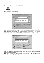
...pushbutton, it 's unable to be 115200. For other settings, please refer to another port). Note: Do not shut the power off or turn the TV set on the computer features, set the FLASH write program begins to run ; Select corresponding serial port (if it 's ready to run . Switch ...on again. Otherwise it on TV set up the serial port (COM Port). FlashUpgraderNT (use under window 2000/XP/NT) FlashUpgrader (use under window 98), The following interfaces will become ...
...pushbutton, it 's unable to be 115200. For other settings, please refer to another port). Note: Do not shut the power off or turn the TV set on the computer features, set the FLASH write program begins to run ; Select corresponding serial port (if it 's ready to run . Switch ...on again. Otherwise it on TV set up the serial port (COM Port). FlashUpgraderNT (use under window 2000/XP/NT) FlashUpgrader (use under window 98), The following interfaces will become ...
Service Manual
Page 14
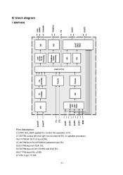
IC block diagram 1.MSP3420 Pins description: 2,3 PIN: SCL,SDA applied for control the operation of IC . 27,28 PIN: output left and right sound channel R/L to speaker processor. 36,37 PIN:AV OUT of sound R/L. 47,48 PIN:D4-1/D4-2/PCMCIA selected input R/L. 50,51 PIN:Input of BS 67 PIN: Input TV SIF. 11 R/L 53,54 PIN:Input of AV1/SVHS and AV2 R/L. 56,57 PIN:Input R/L of VGA.
IC block diagram 1.MSP3420 Pins description: 2,3 PIN: SCL,SDA applied for control the operation of IC . 27,28 PIN: output left and right sound channel R/L to speaker processor. 36,37 PIN:AV OUT of sound R/L. 47,48 PIN:D4-1/D4-2/PCMCIA selected input R/L. 50,51 PIN:Input of BS 67 PIN: Input TV SIF. 11 R/L 53,54 PIN:Input of AV1/SVHS and AV2 R/L. 56,57 PIN:Input R/L of VGA.
Service Manual
Page 15
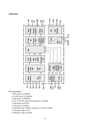
2.VPC3230 Pins description: 4 PIN: Input U of PCMCIA. 5,73 PIN: Input Y of PCMCIA. 6 PIN: Input V of PCMCIA 31-34, 37-40 PIN: output format signal of TV/BS. 12 ITU-R656 70 PIN:Video of AV OUT 71 PIN:Input C of SVHS. 72 PIN:input Video (SVHS in priority) of Y or AV1 of SVHS. 74 PIN:input Video of AV2. 75 PIN:input Video of .
2.VPC3230 Pins description: 4 PIN: Input U of PCMCIA. 5,73 PIN: Input Y of PCMCIA. 6 PIN: Input V of PCMCIA 31-34, 37-40 PIN: output format signal of TV/BS. 12 ITU-R656 70 PIN:Video of AV OUT 71 PIN:Input C of SVHS. 72 PIN:input Video (SVHS in priority) of Y or AV1 of SVHS. 74 PIN:input Video of AV2. 75 PIN:input Video of .

Service Manual
Page 24
... 24V-A of power supply board no can operation? yes Adjust CPU board again YPRPB Which is no VGA/DVI signal of channels Replacing CPU board TV Testing power supply (+5V-V) of video processing board Check input 22V no of sound conversion board no Replacing no U30 Testing yes PIN65 of TP1...
... 24V-A of power supply board no can operation? yes Adjust CPU board again YPRPB Which is no VGA/DVI signal of channels Replacing CPU board TV Testing power supply (+5V-V) of video processing board Check input 22V no of sound conversion board no Replacing no U30 Testing yes PIN65 of TP1...

Operation Manual
Page 2
... Signal ...21 Selecting a Menu Language...21 Setting Picture ...22 Customizing the Picture ...22 Using the Preset Picture Mode...22 Setting System ...23 Setting System In TV Mode ...23 Adjusting Screen Aspect ...23 Reducing Picture Noise...23 VCR mode...23 Loading Default Values ...23 Setting System In VGA Mode ...24 Changing the...
... Signal ...21 Selecting a Menu Language...21 Setting Picture ...22 Customizing the Picture ...22 Using the Preset Picture Mode...22 Setting System ...23 Setting System In TV Mode ...23 Adjusting Screen Aspect ...23 Reducing Picture Noise...23 VCR mode...23 Loading Default Values ...23 Setting System In VGA Mode ...24 Changing the...

Operation Manual
Page 3
...the TVPC Frame ...31 Adjusting the Size of TVPC Frame...31 Viewing Picture-by-Picture ...31 Using Hotkeys ...32 Setting Sleep Timer...32 Setting Audio Mode ...32 To pause Picture...32 Viewing Closed Captions...33 Turning Closed Caption On or Off...33 Setting Closed Caption...33 Setting CC When Mute...33... Adjusting Child Lock Settings ...34 Child Lock...34 Turning Child Lock On or Off...36 Changing the Password ...36 Adjusting the Movie Rating...36 Adjusting the TV ...
...the TVPC Frame ...31 Adjusting the Size of TVPC Frame...31 Viewing Picture-by-Picture ...31 Using Hotkeys ...32 Setting Sleep Timer...32 Setting Audio Mode ...32 To pause Picture...32 Viewing Closed Captions...33 Turning Closed Caption On or Off...33 Setting Closed Caption...33 Setting CC When Mute...33... Adjusting Child Lock Settings ...34 Child Lock...34 Turning Child Lock On or Off...36 Changing the Password ...36 Adjusting the Movie Rating...36 Adjusting the TV ...
Operation Manual
Page 4
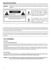
... operate this device. For disposal or recycling information, please contact your local authorities or the Electronic Industries Alliance: www.eia.org FCC STATEMENT FCC Notice LCD TV: A CLASS B digital device This equipment has been tested and found to comply with the limits for proper grounding and, in which case the user may...
... operate this device. For disposal or recycling information, please contact your local authorities or the Electronic Industries Alliance: www.eia.org FCC STATEMENT FCC Notice LCD TV: A CLASS B digital device This equipment has been tested and found to comply with the limits for proper grounding and, in which case the user may...

Operation Manual
Page 5
...) that produce heat. 9.Grounding or Polarization---Do not defeat the safety purpose of improper attachments can cause overheating and/or shorten the life of your LCD TV product, please read and understood before using the product. 1. Heed all instructions---All operating instructions must be followed. 5. Follow all warnings---All warnings on safety...
...) that produce heat. 9.Grounding or Polarization---Do not defeat the safety purpose of improper attachments can cause overheating and/or shorten the life of your LCD TV product, please read and understood before using the product. 1. Heed all instructions---All operating instructions must be followed. 5. Follow all warnings---All warnings on safety...

Operation Manual
Page 8
Preparations Using the Remote Control
Preparations Using the Remote Control
Operation Manual
Page 9
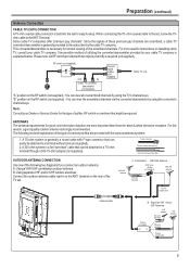
... (not supplied) OUT IN 300-ohm twin-lead 75-ohm or coaxial cable 6 Note: Consult your Dealer or Service Center for the type of the TV set , screw the 75ohm cable to the ANT. terminal on the RF switch (not supplied) : You can be attached to a 75-ohm terminal through a...cable to the set . For this reason, a good quality outdoor antenna is a flat "twin-lead" cable that can view all unscrambled channels by using the TV's channel keys. F-type connector 75-ohm coaxial cable (round) 300-ohm twin-lead cable (flat) OUTDOOR ANTENNA CONNECTION Use one of the following is a brief...
... (not supplied) OUT IN 300-ohm twin-lead 75-ohm or coaxial cable 6 Note: Consult your Dealer or Service Center for the type of the TV set , screw the 75ohm cable to the ANT. terminal on the RF switch (not supplied) : You can be attached to a 75-ohm terminal through a...cable to the set . For this reason, a good quality outdoor antenna is a flat "twin-lead" cable that can view all unscrambled channels by using the TV's channel keys. F-type connector 75-ohm coaxial cable (round) 300-ohm twin-lead cable (flat) OUTDOOR ANTENNA CONNECTION Use one of the following is a brief...

Operation Manual
Page 10
... Menu, press these buttons to choose the OSD items. Note: Functions of VOL+/-, CH+/-, MENU, SOURCE and POWER are also provided to directly change the TV channel; Press it again to turn the unit ON from STANDBY mode. POWER Press this button to directly increase or decrease the sound volume level...
... Menu, press these buttons to choose the OSD items. Note: Functions of VOL+/-, CH+/-, MENU, SOURCE and POWER are also provided to directly change the TV channel; Press it again to turn the unit ON from STANDBY mode. POWER Press this button to directly increase or decrease the sound volume level...

Operation Manual
Page 13
.... SRS technology is a trademark of Controls (continued) 12. SOUND MODE 19 Sound mode select 14 20 15 21 22. TV/PC To activate TVPC function Note: The TVPC function means you may view a TV program from a mini window while the main window is displaying a PC screen. * The SRS symbo is incorporated under...
.... SRS technology is a trademark of Controls (continued) 12. SOUND MODE 19 Sound mode select 14 20 15 21 22. TV/PC To activate TVPC function Note: The TVPC function means you may view a TV program from a mini window while the main window is displaying a PC screen. * The SRS symbo is incorporated under...

Operation Manual
Page 14
... IN AV IN VIDEO L AUDIO R Rear of the external equipment may be different depending on the unit and VCR. To play VCR 1. Turn on your LCD TV , press INPUT button on your VCR , insert a videotape and press the Play button. Note: For better video, you can result in image or color problems...
... IN AV IN VIDEO L AUDIO R Rear of the external equipment may be different depending on the unit and VCR. To play VCR 1. Turn on your LCD TV , press INPUT button on your VCR , insert a videotape and press the Play button. Note: For better video, you can result in image or color problems...

Operation Manual
Page 15
... between the Audio (L/R)/Video jacks on the remote control. 2. Please read the owner's manual of the camcorder may be different and is dependent on your LCD TV , press INPUT button on the unit and camcorder. To playback Camcorder 1. Note: The operations of your camcorder owner's manual.) 4. Connect a Camcorder AV OUT AV2 INPUT...
... between the Audio (L/R)/Video jacks on the remote control. 2. Please read the owner's manual of the camcorder may be different and is dependent on your LCD TV , press INPUT button on the unit and camcorder. To playback Camcorder 1. Note: The operations of your camcorder owner's manual.) 4. Connect a Camcorder AV OUT AV2 INPUT...


