
Operating Instructions
Page 2
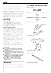
... screen or CRT monitor near to turn the connected devices off from improper installation, improper use, modification, or natural disasters. 2 CHECKING THE ACCESSORIES 7 Speaker Cable × 2 7 Speakers Mounting Screw (M4 × 10 mm: Black) × 8 7 Speakers Mounting Screw (M5 × 10 mm: Black) × 8 7 Speaker Mounting Bracket For LEFT-TOP For LEFT-BOTTOM For RIGHT-TOP For RIGHT-BOTTOM 7 Cushions × 2 7 Operating Instructions × 1 About installation and setting ÷ Attach the...
... screen or CRT monitor near to turn the connected devices off from improper installation, improper use, modification, or natural disasters. 2 CHECKING THE ACCESSORIES 7 Speaker Cable × 2 7 Speakers Mounting Screw (M4 × 10 mm: Black) × 8 7 Speakers Mounting Screw (M5 × 10 mm: Black) × 8 7 Speaker Mounting Bracket For LEFT-TOP For LEFT-BOTTOM For RIGHT-TOP For RIGHT-BOTTOM 7 Cushions × 2 7 Operating Instructions × 1 About installation and setting ÷ Attach the...
Operating Instructions
Page 3
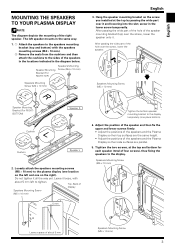
...-TOP) Speakers Mounting Screw (M4 × 10 mm) Speakers Mounting Screw (M4 × 10 mm) English 3. Speakers Mounting Screw (M5 × 10 mm) Leave a space of the speakers in the locations indicated in the diagram below. After passing the wide part of the hole of Display Speakers Mounting Screw (M5 × 10 mm) 5 mm Tighten the bottom speaker mounting bracket to the display temporarily (one on the left speaker mounts in...
...-TOP) Speakers Mounting Screw (M4 × 10 mm) Speakers Mounting Screw (M4 × 10 mm) English 3. Speakers Mounting Screw (M5 × 10 mm) Leave a space of the speakers in the locations indicated in the diagram below. After passing the wide part of the hole of Display Speakers Mounting Screw (M5 × 10 mm) 5 mm Tighten the bottom speaker mounting bracket to the display temporarily (one on the left speaker mounts in...
Operating Instructions
Page 4
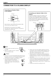
... operation or malfunction. • Incorrect connections of the speaker cable to the right or left of the Plasma Display terminals with the gray line to the ª terminals and the white cable to the polarity of the cable. • When you may result in insufficient stereo sound effects, delivering poor bass sounds or unstable sound image. • Bundle the code without pulling the cord...
... operation or malfunction. • Incorrect connections of the speaker cable to the right or left of the Plasma Display terminals with the gray line to the ª terminals and the white cable to the polarity of the cable. • When you may result in insufficient stereo sound effects, delivering poor bass sounds or unstable sound image. • Bundle the code without pulling the cord...
Operating Instructions
Page 5
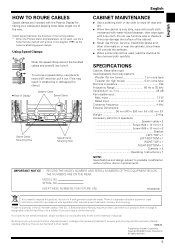
... THE MODEL NUMBER AND SERIAL NUMBERS OF THIS EQUIPMENT BELOW. KEEP THESE NUMBERS FOR FUTURE USE. MODEL NO. There is not used electronic products in the diagram ( ) as the holes for 2 speakers Speaker cable × 2 Screw (M4 × 10 mm) × 8 Screw (M5 × 10 mm) × 8 Bracket LEFT-TOP × 1 LEFT-BOTTOM × 1 RIGHT-TOP × 1 RIGHT-BOTTOM × 1 Cushions × 2 Operating Instructions × 1 NOTE: Specifications and design...
... THE MODEL NUMBER AND SERIAL NUMBERS OF THIS EQUIPMENT BELOW. KEEP THESE NUMBERS FOR FUTURE USE. MODEL NO. There is not used electronic products in the diagram ( ) as the holes for 2 speakers Speaker cable × 2 Screw (M4 × 10 mm) × 8 Screw (M5 × 10 mm) × 8 Bracket LEFT-TOP × 1 LEFT-BOTTOM × 1 RIGHT-TOP × 1 RIGHT-BOTTOM × 1 Cushions × 2 Operating Instructions × 1 NOTE: Specifications and design...
Operating Instructions
Page 12
Published by Pioneer Corporation Copyright © 2006 Pioneer Corporation All rights reserved Printed in China / Imprimé en Chine
Published by Pioneer Corporation Copyright © 2006 Pioneer Corporation All rights reserved Printed in China / Imprimé en Chine


