Operating Instructions
Page 2
... PREVENT THE RISK OF ELECTRIC SHOCK, DO NOT REMOVE COVER (OR BACK). REFER SERVICING TO QUALIFIED SERVICE PERSONNEL. The exclamation point within the product's enclosure that it is installed by mistake in installation or mounting, misuse, modification or a natural disaster. Always have an installation specialist or your Pioneer dealer first. NO USER-SERVICEABLE PARTS INSIDE. Wash hands after handling D36-P4_En...
... PREVENT THE RISK OF ELECTRIC SHOCK, DO NOT REMOVE COVER (OR BACK). REFER SERVICING TO QUALIFIED SERVICE PERSONNEL. The exclamation point within the product's enclosure that it is installed by mistake in installation or mounting, misuse, modification or a natural disaster. Always have an installation specialist or your Pioneer dealer first. NO USER-SERVICEABLE PARTS INSIDE. Wash hands after handling D36-P4_En...
Operating Instructions
Page 3
... appliances such as radios and televisions, use shielded cables and connectors for this serial number on the bottom of the following two conditions: (1) This device may cause undesired operation. D3-4-2-1-9a_En [for US model] IMPORTANT NOTICE The serial number for connections. This is for your enclosed warranty card and keep it in a residential installation. However, there is located on your security. [for...
... appliances such as radios and televisions, use shielded cables and connectors for this serial number on the bottom of the following two conditions: (1) This device may cause undesired operation. D3-4-2-1-9a_En [for US model] IMPORTANT NOTICE The serial number for connections. This is for your enclosed warranty card and keep it in a residential installation. However, there is located on your security. [for...
Operating Instructions
Page 4
... Cursor Position TROUBLESHOOTING ...24 CLEANING ...25 SPECIFICATIONS ...26 17 En Contents SAFETY PRECAUTIONS ...15 ACCESSORIES ...18 NAME AND FUNCTION OF PARTS 18 Main Unit ...18 Pen ...19 Changing the Pen Battery Replacing the Pen Tip INSTALLATION ...20 Attach the Main Unit ...20 Attach the Pen Stand ...20 Connections and System Settings 21 Connecting the Plasma Display to a Computer Adjusting the Plasma Display Installing the Driver Software Connect the Unit...
... Cursor Position TROUBLESHOOTING ...24 CLEANING ...25 SPECIFICATIONS ...26 17 En Contents SAFETY PRECAUTIONS ...15 ACCESSORIES ...18 NAME AND FUNCTION OF PARTS 18 Main Unit ...18 Pen ...19 Changing the Pen Battery Replacing the Pen Tip INSTALLATION ...20 Attach the Main Unit ...20 Attach the Pen Stand ...20 Connections and System Settings 21 Connecting the Plasma Display to a Computer Adjusting the Plasma Display Installing the Driver Software Connect the Unit...
Operating Instructions
Page 5
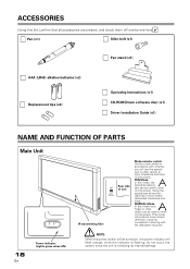
... bolt (x1) Pen stand (x1) AAA (LR03) alkaline batteries (x2) Replacement tips (x2) Operating Instructions (x1) CD-ROM(Driver software disc) (x1) Driver Installation Guide (x1) NAME AND FUNCTION OF PARTS Main Unit 18 En Power indicator (Lights green when ON) IR transmitting filter PEN NORMAL Rear side of more clearly delineated characters and lines. Using the special pen allows the drawing of unit Mode selector switch Set the mode switch...
... bolt (x1) Pen stand (x1) AAA (LR03) alkaline batteries (x2) Replacement tips (x2) Operating Instructions (x1) CD-ROM(Driver software disc) (x1) Driver Installation Guide (x1) NAME AND FUNCTION OF PARTS Main Unit 18 En Power indicator (Lights green when ON) IR transmitting filter PEN NORMAL Rear side of more clearly delineated characters and lines. Using the special pen allows the drawing of unit Mode selector switch Set the mode switch...
Operating Instructions
Page 8
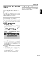
... on connections to a computer. Adjusting the Plasma Display Turn on , select MENU = SETUP = SIGNAL FORMAT = SET, and change the XGA setting to WXGA. Set "SIGNAL FORMAT". To use 1280 x 768 (60 Hz/70 Hz) screen resolution and refresh rate, set the "System Settings". INSTALLATION Installing the Driver Software Consult the Driver Installation Guide for the driver software (provided with this unit). Example of menu displayed on the PDP504CMX/PDP-50MXE1 MENU INPUT1 PICTURE SCREEN SETUP OPTION POWER MANAGEMENT CLAMP POSITION SIGNAL FORMAT : OFF : AUTO : XGA 7 Next, adjust "SCREEN...
... on connections to a computer. Adjusting the Plasma Display Turn on , select MENU = SETUP = SIGNAL FORMAT = SET, and change the XGA setting to WXGA. Set "SIGNAL FORMAT". To use 1280 x 768 (60 Hz/70 Hz) screen resolution and refresh rate, set the "System Settings". INSTALLATION Installing the Driver Software Consult the Driver Installation Guide for the driver software (provided with this unit). Example of menu displayed on the PDP504CMX/PDP-50MXE1 MENU INPUT1 PICTURE SCREEN SETUP OPTION POWER MANAGEMENT CLAMP POSITION SIGNAL FORMAT : OFF : AUTO : XGA 7 Next, adjust "SCREEN...
Operating Instructions
Page 9
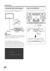
... flashing, since automatic settings are being made during this time. USB Cable Cable clip 22 En Do not touch the screen while the indicator is connected, the accompanying screen message will appear: The power indicator will flash orange, and then flash alternately in green and orange. USB cable Computer NOTE: When connecting a USB hub, use only self-powered types (with AC outlet power connection) with the capacity to hold the unit's USB cable. INSTALLATION Connect...
... flashing, since automatic settings are being made during this time. USB Cable Cable clip 22 En Do not touch the screen while the indicator is connected, the accompanying screen message will appear: The power indicator will flash orange, and then flash alternately in green and orange. USB cable Computer NOTE: When connecting a USB hub, use only self-powered types (with AC outlet power connection) with the capacity to hold the unit's USB cable. INSTALLATION Connect...
Operating Instructions
Page 11
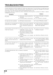
... plasma display's screen ÷ Use the plasma display's calibra- tion mode to computer computer. USB cable is not recognized by computer when connected. ÷ USB port may originate from that of pen tip on . ÷ The holes in rear end of its effective range. ÷ The unit is receiving ultrasonic influence from ÷ Connect USB cable to adjust the vertical screen. Or resolution has been changed. ÷ The plasma display's screen display size setting has been changed. ÷ Driver software is...
... plasma display's screen ÷ Use the plasma display's calibra- tion mode to computer computer. USB cable is not recognized by computer when connected. ÷ USB port may originate from that of pen tip on . ÷ The holes in rear end of its effective range. ÷ The unit is receiving ultrasonic influence from ÷ Connect USB cable to adjust the vertical screen. Or resolution has been changed. ÷ The plasma display's screen display size setting has been changed. ÷ Driver software is...
Operating Instructions
Page 12
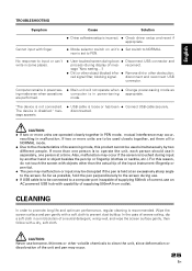
...; Connect USB cable securely. Cannot input with a soft cloth to operate the unit, each person should use benzene, thinners or other obstruction; rear is to prevent dust buildup. red signal filter, blocking signal. are operated closely together in power-saving appropriate. disconnected. Chinese Español Nederlands Italiano Deutsch Français English TROUBLESHOOTING Symptom Cause Solution ÷ Driver software setup is disabled." sage "Now setting...
...; Connect USB cable securely. Cannot input with a soft cloth to operate the unit, each person should use benzene, thinners or other obstruction; rear is to prevent dust buildup. red signal filter, blocking signal. are operated closely together in power-saving appropriate. disconnected. Chinese Español Nederlands Italiano Deutsch Français English TROUBLESHOOTING Symptom Cause Solution ÷ Driver software setup is disabled." sage "Now setting...
Operating Instructions
Page 99
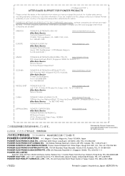
... After-Sales Service Service Division Technical Support Department OCEANIA PIONEER ELECTRONICS AUSTRALIA PTY.LTD. 2211 Princess HWY, Mulgrave VIC3170, Australia After-Sales Service Pioneer Service&Spares Tel: 61-(0)3 9586 6380 Tel: 1-800-988-268 www.pioneeraus.com.au MIDDLE EAST PIONEER GULF FZE www.pioneer-uae.com Lob 11-017, P.O.Box 61226 Jebel Ali, Dubai, U.A.E . If you have any repair facilities. ( For the companies listed...
... After-Sales Service Service Division Technical Support Department OCEANIA PIONEER ELECTRONICS AUSTRALIA PTY.LTD. 2211 Princess HWY, Mulgrave VIC3170, Australia After-Sales Service Pioneer Service&Spares Tel: 61-(0)3 9586 6380 Tel: 1-800-988-268 www.pioneeraus.com.au MIDDLE EAST PIONEER GULF FZE www.pioneer-uae.com Lob 11-017, P.O.Box 61226 Jebel Ali, Dubai, U.A.E . If you have any repair facilities. ( For the companies listed...
Technical Manual
Page 1
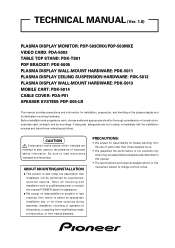
... manual are subject to read instructions indicated by experienced, qualified experts. Be sure to change without notice. TECHNICAL MANUAL (Ver. 1.0) PLASMA DISPLAY MONITOR: PDP-503CMX/PDP-503MXE VIDEO CARD: PDA-5002 TABLE TOP STAND: PDK-TS01 PDP BRACKET: PDK-5005 PLASMA DISPLAY WALL-MOUNT HARDWARE: PDK-5011 PLASMA DISPLAY CEILING SUSPENSION HARDWARE: PDK-5012 PLASMA DISPLAY WALL-MOUNT HARDWARE: PDK-5013 MOBILE CART: PDK-5014 CABLE COVER: PDA-P01 SPEAKER SYSTEM: PDP-S05-LR This manual provides precautions and information for installation...
... manual are subject to read instructions indicated by experienced, qualified experts. Be sure to change without notice. TECHNICAL MANUAL (Ver. 1.0) PLASMA DISPLAY MONITOR: PDP-503CMX/PDP-503MXE VIDEO CARD: PDA-5002 TABLE TOP STAND: PDK-TS01 PDP BRACKET: PDK-5005 PLASMA DISPLAY WALL-MOUNT HARDWARE: PDK-5011 PLASMA DISPLAY CEILING SUSPENSION HARDWARE: PDK-5012 PLASMA DISPLAY WALL-MOUNT HARDWARE: PDK-5013 MOBILE CART: PDK-5014 CABLE COVER: PDA-P01 SPEAKER SYSTEM: PDP-S05-LR This manual provides precautions and information for installation...
Technical Manual
Page 2
....3 Installation on the PDP-503CMX or PDP-503MXE 94 BEFORE BEGINNING ADJUSTMENTS 5.1 Before Beginning Adjustments 96 5.1.1 Operating mode 96 5.1.2 Combination use of remote control unit, operating panel and PC 97 5.1.3 Lists of supported input signals 98 5.1.4 List of adjustable and settable items 102 5.1.5 Last Memory 107 5.2 Normal Operating Mode 108 5.2.1 About normal operating mode 108 5.3 Menu Mode 110 5.3.1 About menu mode 110 5.3.2 Example of menu mode operation 111 5.3.3 Settings in menu mode 113 1) Rewriting the input display 113 2) Setting POWER MANAGEMENT and AUTO POWER...
....3 Installation on the PDP-503CMX or PDP-503MXE 94 BEFORE BEGINNING ADJUSTMENTS 5.1 Before Beginning Adjustments 96 5.1.1 Operating mode 96 5.1.2 Combination use of remote control unit, operating panel and PC 97 5.1.3 Lists of supported input signals 98 5.1.4 List of adjustable and settable items 102 5.1.5 Last Memory 107 5.2 Normal Operating Mode 108 5.2.1 About normal operating mode 108 5.3 Menu Mode 110 5.3.1 About menu mode 110 5.3.2 Example of menu mode operation 111 5.3.3 Settings in menu mode 113 1) Rewriting the input display 113 2) Setting POWER MANAGEMENT and AUTO POWER...

Technical Manual
Page 3
...) Setting COLOR MODE 148 18) Setting MIRROR MODE 149 19) Setting the cooling fan control formula ..... 150 20) Assigning a name to the monitor 151 21) Assigning an ID 152 22) Input settings when using a video card other than the PDA-5002 153 23) Simple checking of internal temperature .. 154 24) Checking the accumulated ON time ......... 155 5.4.4 PICTURE and WHITE BALANCE adjustment values memory area tables 156 5.4.5 SCREEN adjustment values area tables...
...) Setting COLOR MODE 148 18) Setting MIRROR MODE 149 19) Setting the cooling fan control formula ..... 150 20) Assigning a name to the monitor 151 21) Assigning an ID 152 22) Input settings when using a video card other than the PDA-5002 153 23) Simple checking of internal temperature .. 154 24) Checking the accumulated ON time ......... 155 5.4.4 PICTURE and WHITE BALANCE adjustment values memory area tables 156 5.4.5 SCREEN adjustment values area tables...
Technical Manual
Page 5
... accordance with changes in resolutions from 640x400 and 640x480 (VGA) to normal operating conditions (MODE 1, with color-bar signal input). 5 Power-Saving Design This display achieves the lowest power consumption in the industry for commercial applications The is supported in operating environment. Features Features and Functions of the PDP-503CMX/PDP-503MXE Plasma Display Introduces newly developed 50" XGA Wide Plasma Panel The new high-precision XGA 50" wide plasma panel pushes...
... accordance with changes in resolutions from 640x400 and 640x480 (VGA) to normal operating conditions (MODE 1, with color-bar signal input). 5 Power-Saving Design This display achieves the lowest power consumption in the industry for commercial applications The is supported in operating environment. Features Features and Functions of the PDP-503CMX/PDP-503MXE Plasma Display Introduces newly developed 50" XGA Wide Plasma Panel The new high-precision XGA 50" wide plasma panel pushes...
Technical Manual
Page 6
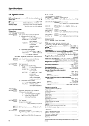
Specifications 2.1 Specifications Light-emitting panel 50-inch plasma display panel Aspect ratio 16 : 9 PEL 1280 × 768 PEL pitch 0.858 (H•RGB trio) × 0.808 (V) mm Viewing angle Horizontal: more than 160 degrees Vertical: more than three tiers Standard accessories Power cord 1 Remote control unit 1 AA battery 2 Wiping cloth 1 Speed clamp 2 Bead Band 2 Operating instructions 1 Warranty card 1 Remote control unit holder 1 Display stand 2 Washer 2 Hexagon socket head screw (M8 x 40 2 CD-ROM (information...
Specifications 2.1 Specifications Light-emitting panel 50-inch plasma display panel Aspect ratio 16 : 9 PEL 1280 × 768 PEL pitch 0.858 (H•RGB trio) × 0.808 (V) mm Viewing angle Horizontal: more than 160 degrees Vertical: more than three tiers Standard accessories Power cord 1 Remote control unit 1 AA battery 2 Wiping cloth 1 Speed clamp 2 Bead Band 2 Operating instructions 1 Warranty card 1 Remote control unit holder 1 Display stand 2 Washer 2 Hexagon socket head screw (M8 x 40 2 CD-ROM (information...

Technical Manual
Page 11
... 1 Display stand 2 Remote control sensor Point the remote control toward the remote sensor to operate the unit. 3 STANDBY/ON indicator This indicator is red during standby mode, and turns to green when the unit is in operation or standby mode. 5 KEY LOCK/UNLOCK Button (concealed button) This switches between main unit panel and remote control operation permitted/forbidden. 6 INPUT button Press to select input. 7 MENU button Press to open and close the on-screen menu. 8 ADJUST (5/∞/3/2) buttons Use to navigate menu screens and to adjust...
... 1 Display stand 2 Remote control sensor Point the remote control toward the remote sensor to operate the unit. 3 STANDBY/ON indicator This indicator is red during standby mode, and turns to green when the unit is in operation or standby mode. 5 KEY LOCK/UNLOCK Button (concealed button) This switches between main unit panel and remote control operation permitted/forbidden. 6 INPUT button Press to select input. 7 MENU button Press to open and close the on-screen menu. 8 ADJUST (5/∞/3/2) buttons Use to navigate menu screens and to adjust...

Technical Manual
Page 12
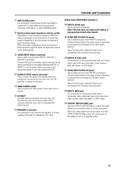
... a personal computer, DVD player, or external RGB decoder. 6 OUTPUT (INPUT1) (mini D-sub 15 pin) Use the OUTPUT (INPUT1) connector to output the video signal to . L ~ R 8Ω ~16Ω S+PEAKE-R 1 CONTROL IN OUT COMBINATION IN OUT RS-232C 23 4 INPUT1 (ON SYNC) ANALOG RGB OUTPUT (ANALOG RGB) G B INPUT2 (H/V SYNC) R HD VD 7Ω5Ô2k.Ω2 AUDIO INPUT OUTPUT (INPUT1/2) 56 7 89 0 Plasma Display Section 1 SPEAKER (R) terminal For connection of an external right speaker.
... a personal computer, DVD player, or external RGB decoder. 6 OUTPUT (INPUT1) (mini D-sub 15 pin) Use the OUTPUT (INPUT1) connector to output the video signal to . L ~ R 8Ω ~16Ω S+PEAKE-R 1 CONTROL IN OUT COMBINATION IN OUT RS-232C 23 4 INPUT1 (ON SYNC) ANALOG RGB OUTPUT (ANALOG RGB) G B INPUT2 (H/V SYNC) R HD VD 7Ω5Ô2k.Ω2 AUDIO INPUT OUTPUT (INPUT1/2) 56 7 89 0 Plasma Display Section 1 SPEAKER (R) terminal For connection of an external right speaker.
Technical Manual
Page 13
... plasma display's INPUT1 or INPUT2, or to the audio output connector of the device connected to the video card's INPUT5#. 0 AUDIO OUTPUT (Stereo mini jack) Use to an external monitor or other component. INPUT5 (DVI-D jack) Use to match the output impedance of the component's synchronization signal is selected. Connect a speaker that have a composite video output jack such as a video deck, video camera, laser disc player, or DVD player. $ AUDIO INPUT4 (RCA Pin jacks) Use to obtain sound...
... plasma display's INPUT1 or INPUT2, or to the audio output connector of the device connected to the video card's INPUT5#. 0 AUDIO OUTPUT (Stereo mini jack) Use to an external monitor or other component. INPUT5 (DVI-D jack) Use to match the output impedance of the component's synchronization signal is selected. Connect a speaker that have a composite video output jack such as a video deck, video camera, laser disc player, or DVD player. $ AUDIO INPUT4 (RCA Pin jacks) Use to obtain sound...
Technical Manual
Page 15
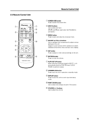
... -screen menu. 4 ADJUST (5/∞/3/2) buttons Use to navigate menu screens and to adjust the volume. 15 Usage of cursor buttons within operations is connected.) 3 MENU button Press to open and close the on the unit. 6 MUTING button Press to mute the volume. 7 AUTO SET UP button When entering a computer signal to INPUT 1 or 2, automatically sets the POSITION and CLOCK/ PHASE to optimum values. 8 STANDBY/ON button Press to put the unit in operation or standby mode. 9 DISPLAY button...
... -screen menu. 4 ADJUST (5/∞/3/2) buttons Use to navigate menu screens and to adjust the volume. 15 Usage of cursor buttons within operations is connected.) 3 MENU button Press to open and close the on the unit. 6 MUTING button Press to mute the volume. 7 AUTO SET UP button When entering a computer signal to INPUT 1 or 2, automatically sets the POSITION and CLOCK/ PHASE to optimum values. 8 STANDBY/ON button Press to put the unit in operation or standby mode. 9 DISPLAY button...
Technical Manual
Page 18
... bright lighting can reduce system service life. 8) Installation partially outdoors The unit is designed for indoor use, and is evenly distributed along the ceiling or floor, as well as on mounting hardware such as hang bolts. 4) Sufficient work space Select a location with a weight capacity sufficient to support the total weight of the display and mounting hardware. 3) Flat, level surfaces Select a flat, level surface for installation, such...
... bright lighting can reduce system service life. 8) Installation partially outdoors The unit is designed for indoor use, and is evenly distributed along the ceiling or floor, as well as on mounting hardware such as hang bolts. 4) Sufficient work space Select a location with a weight capacity sufficient to support the total weight of the display and mounting hardware. 3) Flat, level surfaces Select a flat, level surface for installation, such...

Technical Manual
Page 19
... screen's infrared intensity will be installed in a power distribution series, choose the leakage breaker rating so that it in voltage when switching the unit power on the image displayed. 19 It is grounded. • Do not allow water or other products controlled with infrared remote controls are used by the plasma display in order to inspect the power. • Significant voltage drop between the circuit panel...
... screen's infrared intensity will be installed in a power distribution series, choose the leakage breaker rating so that it in voltage when switching the unit power on the image displayed. 19 It is grounded. • Do not allow water or other products controlled with infrared remote controls are used by the plasma display in order to inspect the power. • Significant voltage drop between the circuit panel...


