Owner's Manual
Page 156
...volume of AV source are used. The backlight of your vehicle. display", for AVIC-F900BT and AVIC-F90BT.) The parking brake is not applied. on Check the settings. The attenuator... no picture. "Rear display" picture disappears. (This information is intended for example a faulty wiring connection. Check [Night mode] setting and make sure [Automatic] is on the backlight. (Page... or not the reverse gear signal input lead (violet) is connected properly. (The navigation system works properly without a significant positioning error. You cannot adjust these with the "Rear ...
...volume of AV source are used. The backlight of your vehicle. display", for AVIC-F900BT and AVIC-F90BT.) The parking brake is not applied. on Check the settings. The attenuator... no picture. "Rear display" picture disappears. (This information is intended for example a faulty wiring connection. Check [Night mode] setting and make sure [Automatic] is on the backlight. (Page... or not the reverse gear signal input lead (violet) is connected properly. (The navigation system works properly without a significant positioning error. You cannot adjust these with the "Rear ...

Owner's Manual
Page 159
... phone with another method again and retry. (Page 52) Your mobile phone can not support this navigation system. nal storage device (USB, SD) but there is no compatibility with navigation system. ! less technology is not too far. Cancel the pairing (connection) and retry. Rejection has ...data and store the data properly. (Page 135) Data Read error. Activate the target phone's Bluetooth wire- Operate the target phone and accept the connection request from the navigation system. (Furthermore, check the connection settings on the exter- Use the appropriate data and store the data...
... phone with another method again and retry. (Page 52) Your mobile phone can not support this navigation system. nal storage device (USB, SD) but there is no compatibility with navigation system. ! less technology is not too far. Cancel the pairing (connection) and retry. Rejection has ...data and store the data properly. (Page 135) Data Read error. Activate the target phone's Bluetooth wire- Operate the target phone and accept the connection request from the navigation system. (Furthermore, check the connection settings on the exter- Use the appropriate data and store the data...
Installation Manual
Page 5
... to allow any leads. Make sure that the cables and wires are routed and secured so they will be exposed to other hazards, and can cause damage to the navigation system that only authorized Pioneer service personnel, who have special training and experience in the mobile... electronics installations, please carefully follow all wiring with the ground from another product. Do not allow the cables...
... to allow any leads. Make sure that the cables and wires are routed and secured so they will be exposed to other hazards, and can cause damage to the navigation system that only authorized Pioneer service personnel, who have special training and experience in the mobile... electronics installations, please carefully follow all wiring with the ground from another product. Do not allow the cables...
Installation Manual
Page 8
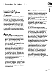
It is necessary to set [AV1 Input] in .) Antenna jack Vehicle antenna WIRED REMOTE INPUT Please see the Instruction Manual for iPod or an appropriate USB storage device. *1 8 En Section 03 Connecting the System Connecting the system The navigation unit 4 m (13 ft. 1 in.) Light gray 5 m (16 ft. 5 in.) RCA connector 2 m (6 ft. 7 in.) Blue 20 cm...
It is necessary to set [AV1 Input] in .) Antenna jack Vehicle antenna WIRED REMOTE INPUT Please see the Instruction Manual for iPod or an appropriate USB storage device. *1 8 En Section 03 Connecting the System Connecting the system The navigation unit 4 m (13 ft. 1 in.) Light gray 5 m (16 ft. 5 in.) RCA connector 2 m (6 ft. 7 in.) Blue 20 cm...
Installation Manual
Page 12
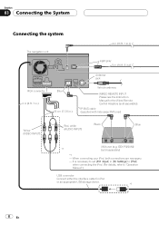
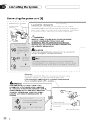
Connection method Pass the extension cord and the lead for AVIC-F700BT and AVIC-F7010BT. CAUTION It is strongly suggested that the speed pulse wire be connected to the power supply side of the parking brake switch. Close the cover. Light green Used to ... TRANSMISSION AND SPEEDOMETER INDICATION. This lead must be connected for accuracy of your authorised Pioneer dealer or an installation professional. If this connection will be unusable. For details, consult your navigation system will increase errors in .) This connection is unnecessary for the speed detection circuit through this ...
Connection method Pass the extension cord and the lead for AVIC-F700BT and AVIC-F7010BT. CAUTION It is strongly suggested that the speed pulse wire be connected to the power supply side of the parking brake switch. Close the cover. Light green Used to ... TRANSMISSION AND SPEEDOMETER INDICATION. This lead must be connected for accuracy of your authorised Pioneer dealer or an installation professional. If this connection will be unusable. For details, consult your navigation system will increase errors in .) This connection is unnecessary for the speed detection circuit through this ...

Installation Manual
Page 16
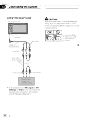
...camera (e.g. The object in rear view may appear closer or more details about the wiring, refer to Connecting the power cord (2) on trailers, or backing into a tight parking spot. Section 03 Connecting the System When connecting a rear view camera When this function for reverse signal) Fuse resistor ...Manual".) ! Do not connect to the rear view camera. OTHER USE MAY RESULT IN INJURY OR DAMAGE. It is to use this navigation system. 5 m (16 ft. 5 in [System Settings] to [On] when connecting the rear view camera. (For details, refer to keep an eye on page 12 Notes ! ...
...camera (e.g. The object in rear view may appear closer or more details about the wiring, refer to Connecting the power cord (2) on trailers, or backing into a tight parking spot. Section 03 Connecting the System When connecting a rear view camera When this function for reverse signal) Fuse resistor ...Manual".) ! Do not connect to the rear view camera. OTHER USE MAY RESULT IN INJURY OR DAMAGE. It is to use this navigation system. 5 m (16 ft. 5 in [System Settings] to [On] when connecting the rear view camera. (For details, refer to keep an eye on page 12 Notes ! ...
Installation Manual
Page 18
... V : Video (Yellow) G : Ground To video output To audio outputs External video component (sold separately) for wiring. It is a case where wiring position differs, images and sounds may be disturbed. If you use other cables, there is necessary to set [AV2 ...Input] in [AV Settings] to [Video] when connecting the external video component. (For details, refer to use a CD-RM10 (sold separately) ! Section 03 Connecting the System Using "AV2 Input" (AV2) The navigation...
... V : Video (Yellow) G : Ground To video output To audio outputs External video component (sold separately) for wiring. It is a case where wiring position differs, images and sounds may be disturbed. If you use other cables, there is necessary to set [AV2 ...Input] in [AV Settings] to [Video] when connecting the external video component. (For details, refer to use a CD-RM10 (sold separately) ! Section 03 Connecting the System Using "AV2 Input" (AV2) The navigation...
Installation Manual
Page 20
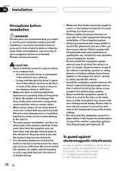
... may damage wires or insulation, leading to a short circuit or other damage to the vehicle. ! To guard against electromagnetic interference In order to prevent interference, set the following installation of the navigation system. ! It could injure the driver or passengers if the vehicle stops suddenly. - Please refer to your navigation system to authorized Pioneer service personnel...
... may damage wires or insulation, leading to a short circuit or other damage to the vehicle. ! To guard against electromagnetic interference In order to prevent interference, set the following installation of the navigation system. ! It could injure the driver or passengers if the vehicle stops suddenly. - Please refer to your navigation system to authorized Pioneer service personnel...
Installation Manual
Page 21
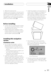
...route them together, or cross them. Places that the connections are correct and the system works properly. Install this navigation system can be displayed correctly. ! Choose a position where this navigation system in the figure below. Installation Section 04 English ! Before installing ! This is ... more than these tolerances increases the potential for instance, near a heater outlet. En 21 If this product, temporarily connect the wiring to a heater, vent or air conditioner. - Before making a final installation of the vehicle. ! Such electromagnetic noise will ...
...route them together, or cross them. Places that the connections are correct and the system works properly. Install this navigation system can be displayed correctly. ! Choose a position where this navigation system in the figure below. Installation Section 04 English ! Before installing ! This is ... more than these tolerances increases the potential for instance, near a heater outlet. En 21 If this product, temporarily connect the wiring to a heater, vent or air conditioner. - Before making a final installation of the vehicle. ! Such electromagnetic noise will ...


