Owner's Manual
Page 11
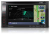
p When using a cellular phone, keep the antenna of the cellular phone away from the battery (or removing the battery itself). However, some items remain. Chapter 01 ing the navigation system to the ...
p When using a cellular phone, keep the antenna of the cellular phone away from the battery (or removing the battery itself). However, some items remain. Chapter 01 ing the navigation system to the ...
Owner's Manual
Page 29
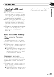
... is scrolled. Arrow indicating the direction of screen displays can select the following information is displayed. Set the route to the place specified with an antenna view (3D map). ! You can be taken by scroll mode on page 46. : Vicinity Search Find POIs (Points Of Interest) in the "Contacts List" on...
... is scrolled. Arrow indicating the direction of screen displays can select the following information is displayed. Set the route to the place specified with an antenna view (3D map). ! You can be taken by scroll mode on page 46. : Vicinity Search Find POIs (Points Of Interest) in the "Contacts List" on...
Owner's Manual
Page 148
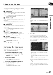
... reception sensitivity, and from how many satellites the signal is displayed. When the GPS antenna is not connected to display the "Top Menu" screen. 2 Touch [Settings]. p This can also be operated using the "Shortcut Menu" screen. 3 Touch [Navi Settings]. ...Checking the connections of a vehicle are connected in positioning Yes No p When the GPS antenna is connected to this navigation system, "OK" is displayed. When the parking brake is released, "Off" is displayed. 4 Illumination When the headlights or small lamps...
... reception sensitivity, and from how many satellites the signal is displayed. When the GPS antenna is not connected to display the "Top Menu" screen. 2 Touch [Settings]. p This can also be operated using the "Shortcut Menu" screen. 3 Touch [Navi Settings]. ...Checking the connections of a vehicle are connected in positioning Yes No p When the GPS antenna is connected to this navigation system, "OK" is displayed. When the parking brake is released, "Off" is displayed. 4 Illumination When the headlights or small lamps...
Owner's Manual
Page 190
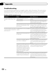
... accuracy. Then start the engine again, and turn the power to Acc ate incorrectly. racy. The quality of the GPS antenna if necessary, or continue driving until reception improves. The most common problems are correct. ate. Turn the ignition key back to...or the nearest authorized Pioneer service facility. Continue driving until reception improves. When using a cellular phone, keep the antenna of the GPS antenna if necessary. is poor, causing reduced positioning accu- Keep the antenna clear. The position of signals from the GPS antenna. 190 En Appendix ...
... accuracy. Then start the engine again, and turn the power to Acc ate incorrectly. racy. The quality of the GPS antenna if necessary, or continue driving until reception improves. The most common problems are correct. ate. Turn the ignition key back to...or the nearest authorized Pioneer service facility. Continue driving until reception improves. When using a cellular phone, keep the antenna of the GPS antenna if necessary. is poor, causing reduced positioning accu- Keep the antenna clear. The position of signals from the GPS antenna. 190 En Appendix ...
Owner's Manual
Page 191
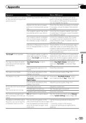
For details, refer to Installation Manual.) Indication of the position of your vehicle Something covers the GPS antenna. Check whether or not the reverse gear signal input lead (violet) is connected properly. (The navigation system works properly without...vehicle's light is not correct. Picture quality adjustment of navigation gui- Check the connection. speaking En 191 Do not cover the GPS antenna with an extreme angle exceeding the installation angle limitations. The volume level will be ad- Check that the cables are properly connected. Confirm...
For details, refer to Installation Manual.) Indication of the position of your vehicle Something covers the GPS antenna. Check whether or not the reverse gear signal input lead (violet) is connected properly. (The navigation system works properly without...vehicle's light is not correct. Picture quality adjustment of navigation gui- Check the connection. speaking En 191 Do not cover the GPS antenna with an extreme angle exceeding the installation angle limitations. The volume level will be ad- Check that the cables are properly connected. Confirm...
Owner's Manual
Page 200
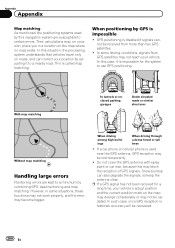
... become bigger. In this situation, the processing system understands that vehicles travel only on roads, and can also degrade the signals, so keep the antenna clear. When positioning by combining GPS, dead reckoning and map matching. However, in a location on the map may diverge considerably or may not ...forest or tall trees ! In such case, once GPS reception is disabled if signals cannot be recovered. 200 En Do not cover the GPS antenna with spray paint or car wax, because this case, it to certain errors. Snow buildup can correct your position by adjusting it is used ...
... become bigger. In this situation, the processing system understands that vehicles travel only on roads, and can also degrade the signals, so keep the antenna clear. When positioning by combining GPS, dead reckoning and map matching. However, in a location on the map may diverge considerably or may not ...forest or tall trees ! In such case, once GPS reception is disabled if signals cannot be recovered. 200 En Do not cover the GPS antenna with spray paint or car wax, because this case, it to certain errors. Snow buildup can correct your position by adjusting it is used ...
Owner's Manual
Page 215
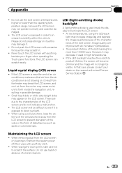
... because of the characteristics of its visibility within the vehicle. Do not push the LCD screen with anything besides your dealer or the nearest authorized Pioneer Service Station. Liquid crystal display (LCD) screen ! When using the LED back- Image quality will improve with a soft dry cloth. ! The ...000 hours. Never touch the LCD screen with excessive force as spots or colored stripes. At low temperatures, using a cellular phone, keep the antenna of the LCD screen and do not press strongly on it . ! En 215 However, it may scratch it as this may decrease if used...
... because of the characteristics of its visibility within the vehicle. Do not push the LCD screen with anything besides your dealer or the nearest authorized Pioneer Service Station. Liquid crystal display (LCD) screen ! When using the LED back- Image quality will improve with a soft dry cloth. ! The ...000 hours. Never touch the LCD screen with excessive force as spots or colored stripes. At low temperatures, using a cellular phone, keep the antenna of the LCD screen and do not press strongly on it . ! En 215 However, it may scratch it as this may decrease if used...
Owner's Manual
Page 224
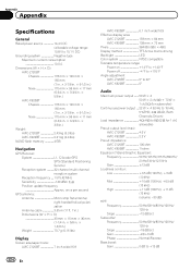
... GPS antenna: Antenna Micro strip flat antenna/ right-handed helical polarization Antenna cable 3.55 m (11 ft. 7 in.) Dimensions (W × H × D 33 mm × 15 mm × 36 mm (1-1/4 in. × 5/8 in. × 1-3/8 in .) Weight: AVIC-Z120BT 2.43 kg (5.3 lbs) AVIC-X920BT 2.01... Both Channels Driven) Load impedance 4 W (4 W to 8 W [2 W for 1 ch] allowable) Preout output level (max): AVIC-Z120BT 4.0 V AVIC-X920BT 2.2 V Preout impedance: AVIC-Z120BT 100 ohm AVIC-X920BT 1 kohm Equalizer (7-Band Graphic Equalizer): Frequency 50 Hz/125 Hz/315 Hz/800 Hz/ 2 kHz/5 kHz/12.5 kHz Gain 12 dB...
... GPS antenna: Antenna Micro strip flat antenna/ right-handed helical polarization Antenna cable 3.55 m (11 ft. 7 in.) Dimensions (W × H × D 33 mm × 15 mm × 36 mm (1-1/4 in. × 5/8 in. × 1-3/8 in .) Weight: AVIC-Z120BT 2.43 kg (5.3 lbs) AVIC-X920BT 2.01... Both Channels Driven) Load impedance 4 W (4 W to 8 W [2 W for 1 ch] allowable) Preout output level (max): AVIC-Z120BT 4.0 V AVIC-X920BT 2.2 V Preout impedance: AVIC-Z120BT 100 ohm AVIC-X920BT 1 kohm Equalizer (7-Band Graphic Equalizer): Frequency 50 Hz/125 Hz/315 Hz/800 Hz/ 2 kHz/5 kHz/12.5 kHz Gain 12 dB...
Installation Manual
Page 2
... users 21 Installing this product 5 To prevent damage 5 - Installation notes 23 - AVIC-X920BT 7 Connecting the system 8 Connecting the power cord (1) 10 Connecting the power cord (2) 12 When connecting to rear video output 18 When connecting the ... 17 - Notice for the blue/white lead 6 Parts supplied 7 - Installation notes 21 - Parts supplied 23 - Adjusting the microphone angle 27 When installing the antenna inside the vehicle (on the sun visor 25 - Contents IMPORTANT INFORMATION ABOUT YOUR NEW NAVIGATION SYSTEM AND THIS MANUAL 3 IMPORTANT SAFEGUARDS PLEASE READ ALL OF...
... users 21 Installing this product 5 To prevent damage 5 - Installation notes 23 - AVIC-X920BT 7 Connecting the system 8 Connecting the power cord (1) 10 Connecting the power cord (2) 12 When connecting to rear video output 18 When connecting the ... 17 - Notice for the blue/white lead 6 Parts supplied 7 - Installation notes 21 - Parts supplied 23 - Adjusting the microphone angle 27 When installing the antenna inside the vehicle (on the sun visor 25 - Contents IMPORTANT INFORMATION ABOUT YOUR NEW NAVIGATION SYSTEM AND THIS MANUAL 3 IMPORTANT SAFEGUARDS PLEASE READ ALL OF...
Installation Manual
Page 5
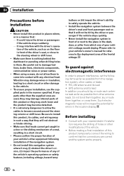
... installation manual. ! Do not use an extension to remain exposed. ! Make sure that they will not obstruct or hinder driving. ! Altering the antenna cable could result in considerable danger. ! En 5 If you do so may become damaged, resulting in such a way that the cables and wires...not directly connect the yellow lead of this unit with or become wound around the steering column or shift lever. Do not cut the GPS antenna cable to shorten it or use 1 W to disconnect the (-) battery cable before connecting the system CAUTION ! Use this product to work properly...
... installation manual. ! Do not use an extension to remain exposed. ! Make sure that they will not obstruct or hinder driving. ! Altering the antenna cable could result in considerable danger. ! En 5 If you do so may become damaged, resulting in such a way that the cables and wires...not directly connect the yellow lead of this unit with or become wound around the steering column or shift lever. Do not cut the GPS antenna cable to shorten it or use 1 W to disconnect the (-) battery cable before connecting the system CAUTION ! Use this product to work properly...
Installation Manual
Page 6
...white lead ! It is employed, do not remove the caps attached to an external power amp's system remote control terminal, the auto-antenna relay control terminal, or the antenna booster power control terminal (max. 300 mA 12 V DC). The control signal is switched off. ! Section 03 Connecting the System ... on this lead as you may cause a short circuit. ! The black cable is properly connected to the owner's manual for the auto-antenna or antenna booster. Ensure that the ground wire is ground. Refer to metal parts of smoke or malfunction. Be sure to connect the * side of...
...white lead ! It is employed, do not remove the caps attached to an external power amp's system remote control terminal, the auto-antenna relay control terminal, or the antenna booster power control terminal (max. 300 mA 12 V DC). The control signal is switched off. ! Section 03 Connecting the System ... on this lead as you may cause a short circuit. ! The black cable is properly connected to the owner's manual for the auto-antenna or antenna booster. Ensure that the ground wire is ground. Refer to metal parts of smoke or malfunction. Be sure to connect the * side of...
Installation Manual
Page 7
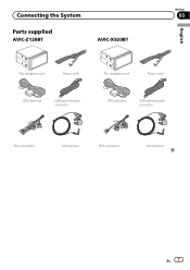
Connecting the System Section 03 Parts supplied AVIC-Z120BT AVIC-X920BT English The navigation unit Power cord The navigation unit Power cord GPS antenna USB and mini-jack connector GPS antenna USB and mini-jack connector RCA connector Microphone RCA connector Microphone En 7
Connecting the System Section 03 Parts supplied AVIC-Z120BT AVIC-X920BT English The navigation unit Power cord The navigation unit Power cord GPS antenna USB and mini-jack connector GPS antenna USB and mini-jack connector RCA connector Microphone RCA connector Microphone En 7
Installation Manual
Page 8
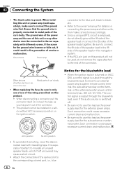
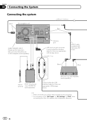
...necessary to set "AV1 Input" in .) IP-BUS cable (supplied with hide-away XM tuner) Black Blue (*2) Vehicle MSN® Direct tuner antenna (e.g. Section 03 Connecting the System Connecting the system Green The navigation unit 3.55 m (11 ft. 8 in.) Blue WIRED REMOTE INPUT Please...Control Adapters (sold separately) (*1) Connect either the interface cable for iPod or an appropriate USB storage device. (*2) - GEX-P920XM) (sold separately). Antenna jack USB and mini-jack connector Connect either the USB Interface Cable for iPod or an appropriate USB storage device. 2 m (6 ft. 7 ...
...necessary to set "AV1 Input" in .) IP-BUS cable (supplied with hide-away XM tuner) Black Blue (*2) Vehicle MSN® Direct tuner antenna (e.g. Section 03 Connecting the System Connecting the system Green The navigation unit 3.55 m (11 ft. 8 in.) Blue WIRED REMOTE INPUT Please...Control Adapters (sold separately) (*1) Connect either the interface cable for iPod or an appropriate USB storage device. (*2) - GEX-P920XM) (sold separately). Antenna jack USB and mini-jack connector Connect either the USB Interface Cable for iPod or an appropriate USB storage device. 2 m (6 ft. 7 ...
Installation Manual
Page 9
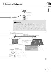
...(*3) with SIRIUS satellite radio tuner) Blue Black Black To IP-BUS output SIRIUS BUS INTERFACE (e.g. Connecting the System Section 03 English 4 m (13 ft. 1 in.) GPS antenna Microphone WARNING · To avoid the risk of accident and the potential violation of images on a display inside a vehicle even by persons other than the...
...(*3) with SIRIUS satellite radio tuner) Blue Black Black To IP-BUS output SIRIUS BUS INTERFACE (e.g. Connecting the System Section 03 English 4 m (13 ft. 1 in.) GPS antenna Microphone WARNING · To avoid the risk of accident and the potential violation of images on a display inside a vehicle even by persons other than the...
Installation Manual
Page 11
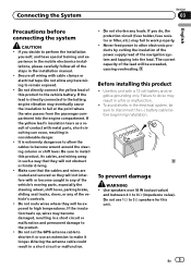
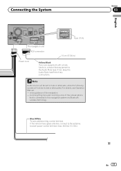
... to this navigation system via Bluetooth wireless technology Blue/White To auto-antenna relay control terminal. If not, keep the Audio Mute lead free of the navigation - incoming Ring tone and incoming voice of the cellular phone that ... A) The navigation unit RCA connector 15 cm (5-7/8 in.) Power cord Yellow/Black If you use equipment with a mute function, connect that is connected to the antenna booster power control terminal (max. 300 mA 12 V DC). For details, see Operation Manual. -
... to this navigation system via Bluetooth wireless technology Blue/White To auto-antenna relay control terminal. If not, keep the Audio Mute lead free of the navigation - incoming Ring tone and incoming voice of the cellular phone that ... A) The navigation unit RCA connector 15 cm (5-7/8 in.) Power cord Yellow/Black If you use equipment with a mute function, connect that is connected to the antenna booster power control terminal (max. 300 mA 12 V DC). For details, see Operation Manual. -
Installation Manual
Page 20
...your nearest dealer if installation requires the drilling of the driver's seat, or close to the vehicle. ! Be careful not to your vehicle's other antenna leads. To ensure proper installation, use the supplied parts in a short circuit. ! Make sure that they may work loose and the product may ... to allow them . Do not install this navigation system, other than the supplied ones are correct and the system works properly. 20 En GPS antenna and its lead ! Consult with your vehicle's airbags would deploy. When using screws, do not allow the cables to a short circuit or other...
...your nearest dealer if installation requires the drilling of the driver's seat, or close to the vehicle. ! Be careful not to your vehicle's other antenna leads. To ensure proper installation, use the supplied parts in a short circuit. ! Make sure that they may work loose and the product may ... to allow them . Do not install this navigation system, other than the supplied ones are correct and the system works properly. 20 En GPS antenna and its lead ! Consult with your vehicle's airbags would deploy. When using screws, do not allow the cables to a short circuit or other...
Installation Manual
Page 23
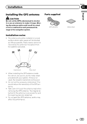
Radio waves cannot be blocked as little as this is not used, the reception sensitivity will be received by the antenna if reception from the satellite is very powerful, and the lead may affect its performance. Section 04 Metal sheet English Dashboard Rear shelf ...an extension to make it longer. Installation Installing the GPS antenna CAUTION Do not cut the accessory metal sheet. The antenna should be installed on a level surface where radio waves will be sure to the antenna is blocked. Altering the antenna cable could result in a short circuit or malfunction and permanent...
Radio waves cannot be blocked as little as this is not used, the reception sensitivity will be received by the antenna if reception from the satellite is very powerful, and the lead may affect its performance. Section 04 Metal sheet English Dashboard Rear shelf ...an extension to make it longer. Installation Installing the GPS antenna CAUTION Do not cut the accessory metal sheet. The antenna should be installed on a level surface where radio waves will be sure to the antenna is blocked. Altering the antenna cable could result in a short circuit or malfunction and permanent...
Installation Manual
Page 24
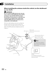
...properly and securely affix to secure the lead where necessary inside the vehicle (on the dashboard or rear shelf) WARNING Do not install the GPS antenna over any sensors or vents on the surface if it is removed. Clamps Use separately sold clamps to the dashboard. Section 04 Installation When ...installing the antenna inside the vehicle. 24 En Make sure the surface is fastened with the proper functioning of such sensors or vents and may leave a mark ...
...properly and securely affix to secure the lead where necessary inside the vehicle (on the dashboard or rear shelf) WARNING Do not install the GPS antenna over any sensors or vents on the surface if it is removed. Clamps Use separately sold clamps to the dashboard. Section 04 Installation When ...installing the antenna inside the vehicle. 24 En Make sure the surface is fastened with the proper functioning of such sensors or vents and may leave a mark ...
Installation Manual
Page 25
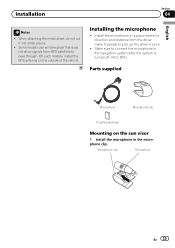
Install the microphone in the microphone clip. Microphone clip Microphone En 25 On such models, install the GPS antenna on the sun visor 1 Install the microphone in a place where its direction and distance from GPS satellites to the navigation system after the system is ...
Install the microphone in the microphone clip. Microphone clip Microphone En 25 On such models, install the GPS antenna on the sun visor 1 Install the microphone in a place where its direction and distance from GPS satellites to the navigation system after the system is ...


