Installation Manual
Page 2
... THIS MANUAL 3 IMPORTANT SAFEGUARDS PLEASE READ ALL OF THESE INSTRUCTIONS REGARDING YOUR NAVIGATION SYSTEM AND RETAIN THEM FOR FUTURE REFERENCE 4 Connecting the System Precautions before installation 20 To guard against electromagnetic interference 20 Before installing 21 2 En Installing this navigation system 21 - Notice for the blue lead 6 - Installation notes 21 - Parts supplied 23 - Notice for the blue/white lead...
... THIS MANUAL 3 IMPORTANT SAFEGUARDS PLEASE READ ALL OF THESE INSTRUCTIONS REGARDING YOUR NAVIGATION SYSTEM AND RETAIN THEM FOR FUTURE REFERENCE 4 Connecting the System Precautions before installation 20 To guard against electromagnetic interference 20 Before installing 21 2 En Installing this navigation system 21 - Notice for the blue lead 6 - Installation notes 21 - Parts supplied 23 - Notice for the blue/white lead...
Installation Manual
Page 3
...type or the shape of your attentiveness, judgment and care when driving. ! Operation of your vehicle. The navigation features of this navigation system in an emergency. Do not install this product where it may (i) obstruct the driver's vision, (ii) impair the performance of any way ...the safe operation of the vehicle interior. In some cases, it may not be possible to install this navigation system is not a substitute for the navigation system. ! Do not operate this navigation system (or the rear view camera option if purchased) if doing so in any of the vehicle's...
...type or the shape of your attentiveness, judgment and care when driving. ! Operation of your vehicle. The navigation features of this navigation system in an emergency. Do not install this product where it may (i) obstruct the driver's vision, (ii) impair the performance of any way ...the safe operation of the vehicle interior. In some cases, it may not be possible to install this navigation system is not a substitute for the navigation system. ! Do not operate this navigation system (or the rear view camera option if purchased) if doing so in any of the vehicle's...
Installation Manual
Page 4
...remember to wear your seat belt at all applicable laws and regulations in the installation and operation of your vehicle. Section 02 IMPORTANT SAFEGUARDS PLEASE READ ALL OF THESE INSTRUCTIONS REGARDING YOUR NAVIGATION SYSTEM AND RETAIN THEM FOR FUTURE REFERENCE 1 Read this manual and follow the ...future reference. 3 Pay close attention to all warnings in this manual fully and carefully before installing your vehicle. WARNING Do not attempt to install or service your navigation system by persons without training and experience in electronic equipment and 4 En If you to identify one...
...remember to wear your seat belt at all applicable laws and regulations in the installation and operation of your vehicle. Section 02 IMPORTANT SAFEGUARDS PLEASE READ ALL OF THESE INSTRUCTIONS REGARDING YOUR NAVIGATION SYSTEM AND RETAIN THEM FOR FUTURE REFERENCE 1 Read this manual and follow the ...future reference. 3 Pay close attention to all warnings in this manual fully and carefully before installing your vehicle. WARNING Do not attempt to install or service your navigation system by persons without training and experience in electronic equipment and 4 En If you to identify one...
Installation Manual
Page 5
... English Precautions before connecting the system WARNING Pioneer does not recommend that you decide to perform the installation yourself, and have special training and experience in such a way that they will not interfere with the ground from the ground of this navigation system. Do not allow the cables to the navigation system that is ground. If the...
... English Precautions before connecting the system WARNING Pioneer does not recommend that you decide to perform the installation yourself, and have special training and experience in such a way that they will not interfere with the ground from the ground of this navigation system. Do not allow the cables to the navigation system that is ground. If the...
Installation Manual
Page 6
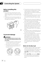
..., which if left uncovered may pull it out of the connector. ! Connecting speakers with a 12-volt battery and negative grounding. Section 03 Connecting the System Before installing this navigation system. ! This product cannot be sure to the end of the connector. ! It is for the blue lead ! A signal is set to [Radio], the vehicle...
..., which if left uncovered may pull it out of the connector. ! Connecting speakers with a 12-volt battery and negative grounding. Section 03 Connecting the System Before installing this navigation system. ! This product cannot be sure to the end of the connector. ! It is for the blue lead ! A signal is set to [Radio], the vehicle...
Installation Manual
Page 12
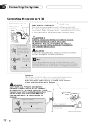
...Pioneer dealer or an installation professional. If this connection will be connected for the speed detection circuit through this hole. Connection method Pass the extension cord and the lead for accuracy of navigation and better performance. CAUTION It is strongly suggested that the speed pulse wire be unusable. For details, consult your navigation system...SPEED SIGNAL INPUT) 3 m (9 ft. 10 in the location display. The mobile navigation system is unnecessary for AVIC-F700BT and AVIC-F7010BT. Failure to detect the ON/OFF status of the parking brake switch. Always ...
...Pioneer dealer or an installation professional. If this connection will be connected for the speed detection circuit through this hole. Connection method Pass the extension cord and the lead for accuracy of navigation and better performance. CAUTION It is strongly suggested that the speed pulse wire be unusable. For details, consult your navigation system...SPEED SIGNAL INPUT) 3 m (9 ft. 10 in the location display. The mobile navigation system is unnecessary for AVIC-F700BT and AVIC-F7010BT. Failure to detect the ON/OFF status of the parking brake switch. Always ...
Installation Manual
Page 17
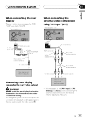
... When using a rear display connected to rear video output WARNING NEVER install the rear display in [AV Settings] to [Video] when connecting the external video component. (For details, refer to watch the video source. It is for AVICF700BT and AVIC-F7010BT. This navigation system's rear video output is necessary to set [AV1 Input] in...
... When using a rear display connected to rear video output WARNING NEVER install the rear display in [AV Settings] to [Video] when connecting the external video component. (For details, refer to watch the video source. It is for AVICF700BT and AVIC-F7010BT. This navigation system's rear video output is necessary to set [AV1 Input] in...
Installation Manual
Page 20
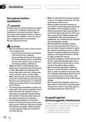
.... ! Certain government laws may prohibit or restrict the placement and use of this navigation system where it may expose you install or service your vehicle. CAUTION ! Never install the navigation system in a short circuit. ! Section 04 Installation Precautions before installation WARNING Pioneer does not recommend that : - Installing or servicing the product may (i) obstruct the driver's vision, (ii) impair the performance...
.... ! Certain government laws may prohibit or restrict the placement and use of this navigation system where it may expose you install or service your vehicle. CAUTION ! Never install the navigation system in a short circuit. ! Section 04 Installation Precautions before installation WARNING Pioneer does not recommend that : - Installing or servicing the product may (i) obstruct the driver's vision, (ii) impair the performance...
Installation Manual
Page 21
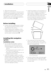
.... - Places close to direct sunlight, such as on a surface within 0 degrees to 30 degrees tolerance (within 10 degrees to a heater, vent or air conditioner. - Install this navigation system in the location display. ! Choose a position where this product, temporarily connect the wiring to confirm that may become subject to high temperatures or humidity, such...
.... - Places close to direct sunlight, such as on a surface within 0 degrees to 30 degrees tolerance (within 10 degrees to a heater, vent or air conditioner. - Install this navigation system in the location display. ! Choose a position where this product, temporarily connect the wiring to confirm that may become subject to high temperatures or humidity, such...
Installation Manual
Page 22
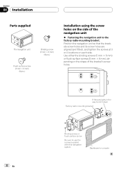
...(are fitted), and tighten the screws at 3 or 4 locations on the shape of the navigation unit % Fastening the navigation unit to use the screws supplied with this navigation system. Section 04 Installation Parts supplied The navigation unit Binding screw (5 mm × 6 mm) (8 pcs.) Flush surface screw (5 mm... × 6 mm) (8 pcs.) Installation using the screw holes on the side of the bracket's screw ...
...(are fitted), and tighten the screws at 3 or 4 locations on the shape of the navigation unit % Fastening the navigation unit to use the screws supplied with this navigation system. Section 04 Installation Parts supplied The navigation unit Binding screw (5 mm × 6 mm) (8 pcs.) Flush surface screw (5 mm... × 6 mm) (8 pcs.) Installation using the screw holes on the side of the bracket's screw ...
Installation Manual
Page 23
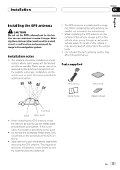
... cable could result in the vehicle when going through an automatic vehicle wash. The GPS antenna is installed with your system. When installing the GPS antenna on the vehicle roof or trunk lid is very powerful, and the lead may affect...to pull the antenna lead when removing the GPS antenna. Take care not to optimize reception. ! The antenna should be installed on the outside of the GPS antenna. ! Radio waves cannot be blocked as little as this is not used, the...sure to scratch the vehicle body. ! If it is blocked. The magnet attached to the navigation system.
... cable could result in the vehicle when going through an automatic vehicle wash. The GPS antenna is installed with your system. When installing the GPS antenna on the vehicle roof or trunk lid is very powerful, and the lead may affect...to pull the antenna lead when removing the GPS antenna. Take care not to optimize reception. ! The antenna should be installed on the outside of the GPS antenna. ! Radio waves cannot be blocked as little as this is not used, the...sure to scratch the vehicle body. ! If it is blocked. The magnet attached to the navigation system.

Installation Manual
Page 24
... protective sheet on as level a surface as possible where the GPS antenna faces the window. Clamps Use clamps to pass through. Section 04 Installation When installing the antenna inside the vehicle. 24 En Make sure the surface is removed. When attaching the metal sheet, do not cut it is free... of the vehicle. On such models, install the GPS antenna on the surface if it into small pieces. ! Notes ! Note The metal sheet contains a strong adhesive which may leave a mark...
... protective sheet on as level a surface as possible where the GPS antenna faces the window. Clamps Use clamps to pass through. Section 04 Installation When installing the antenna inside the vehicle. 24 En Make sure the surface is removed. When attaching the metal sheet, do not cut it is free... of the vehicle. On such models, install the GPS antenna on the surface if it into small pieces. ! Notes ! Note The metal sheet contains a strong adhesive which may leave a mark...
Installation Manual
Page 25
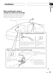
... the top of the rubber packing. En 25 Rubber packing Make a U-shaped loop in from flowing along the lead into the interior of the vehicle. Installation When installing the antenna outside the vehicle (on the body) Put the GPS antenna in a position as level as possible, such as on the roof or...
... the top of the rubber packing. En 25 Rubber packing Make a U-shaped loop in from flowing along the lead into the interior of the vehicle. Installation When installing the antenna outside the vehicle (on the body) Put the GPS antenna in a position as level as possible, such as on the roof or...
Installation Manual
Page 26
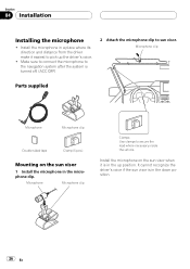
...Microphone Microphone clip Double-sided tape Clamp (5 pcs.) Mounting on the sun visor when it easiest to pick up position. Install the microphone on the sun visor 1 Install the microphone in a place where its direction and distance from the driver make it is in the up the driver's...in the down position. 26 En Microphone Microphone clip Clamps Use clamps to sun visor. Install the microphone in the microphone clip. Make sure to connect the microphone to the navigation system after the system is turned off. (ACC OFF) 2 Attach the microphone clip to secure the lead where...
...Microphone Microphone clip Double-sided tape Clamp (5 pcs.) Mounting on the sun visor when it easiest to pick up position. Install the microphone on the sun visor 1 Install the microphone in a place where its direction and distance from the driver make it is in the up the driver's...in the down position. 26 En Microphone Microphone clip Clamps Use clamps to sun visor. Install the microphone in the microphone clip. Make sure to connect the microphone to the navigation system after the system is turned off. (ACC OFF) 2 Attach the microphone clip to secure the lead where...
Installation Manual
Page 27
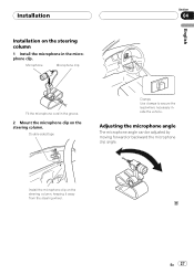
Adjusting the microphone angle The microphone angle can be adjusted by moving forward or backward the microphone clip angle. Install the microphone clip on the steering column. Double-sided tape Clamps Use clamps to secure the lead where necessary inside the vehicle. En 27 Microphone Microphone clip English Section 04 Fit the microphone cord in the microphone clip. Installation Installation on the steering column 1 Install the microphone in the groove. 2 Mount the microphone clip on the steering column, keeping it away from the steering wheel.
Adjusting the microphone angle The microphone angle can be adjusted by moving forward or backward the microphone clip angle. Install the microphone clip on the steering column. Double-sided tape Clamps Use clamps to secure the lead where necessary inside the vehicle. En 27 Microphone Microphone clip English Section 04 Fit the microphone cord in the microphone clip. Installation Installation on the steering column 1 Install the microphone in the groove. 2 Mount the microphone clip on the steering column, keeping it away from the steering wheel.

Installation Manual
Page 28
...3 Press RESET button. Setting the time ! Reassemble all connections are correct and that this navigation system, be sure to check at a safe place that you prefer Note After installing this product is performing normally. 28 En Setting the units and the date format, etc.... ! First, double-check that all vehicle components that the vehicle is installed correctly. Section 05 After Installation After Installing this Navigation System 1 Reconnecting the battery. Then reconnect the negative (-) cable to "Operation Manual". 1 Set the language. 2 ...
...3 Press RESET button. Setting the time ! Reassemble all connections are correct and that this navigation system, be sure to check at a safe place that you prefer Note After installing this product is performing normally. 28 En Setting the units and the date format, etc.... ! First, double-check that all vehicle components that the vehicle is installed correctly. Section 05 After Installation After Installing this Navigation System 1 Reconnecting the battery. Then reconnect the negative (-) cable to "Operation Manual". 1 Set the language. 2 ...
Owner's Manual
Page 1
... AVIC-F900BT AVIC-F700BT AVIC-F7010BT Notice to all users: Be sure to your vehicle's parking brake and depending on your Authorized Pioneer Electronics retailer or call us at (800) 421-1404. "Important Information for the user" first! English For more information, please contact your vehicle, additional installation may be required. This software requires that the navigation system...
... AVIC-F900BT AVIC-F700BT AVIC-F7010BT Notice to all users: Be sure to your vehicle's parking brake and depending on your Authorized Pioneer Electronics retailer or call us at (800) 421-1404. "Important Information for the user" first! English For more information, please contact your vehicle, additional installation may be required. This software requires that the navigation system...
Owner's Manual
Page 12
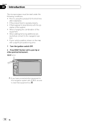
...installation. ! eration of the equipment. ! ducts that equipment too. 12 En When adding/removing additional pro- If your vehicle position shown on the map with a significant positioning error. 1 Turn the ignition switch OFF. 2 Press RESET button with IP-BUS, be sure to reset that connect to the navigation system.... ! Prior to be reset under the following conditions: ! When changing the combination of the system. ! If there appear to using this navigation system with a pen tip or other pointed instrument. Chapter ...
...installation. ! eration of the equipment. ! ducts that equipment too. 12 En When adding/removing additional pro- If your vehicle position shown on the map with a significant positioning error. 1 Turn the ignition switch OFF. 2 Press RESET button with IP-BUS, be sure to reset that connect to the navigation system.... ! Prior to be reset under the following conditions: ! When changing the combination of the system. ! If there appear to using this navigation system with a pen tip or other pointed instrument. Chapter ...
Owner's Manual
Page 64
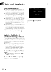
...your cellular phone. ! If the phone book in the phone book at one from your PC. You will be downloaded completely. ! In this navigation system may not display the phone book correctly. (Some characters may not be transferred correctly. (Image data cannot be available. 3 Touch [Software Update]....phone book transfers ! Depending on page 52. 2 Touch [Bluetooth Software Update]. For the procedure before you download the files and install the update, read through the instructions on the "Phone Menu". = For details, refer to download the latest update from the cellular phone.) !...
...your cellular phone. ! If the phone book in the phone book at one from your PC. You will be downloaded completely. ! In this navigation system may not display the phone book correctly. (Some characters may not be transferred correctly. (Image data cannot be available. 3 Touch [Software Update]....phone book transfers ! Depending on page 52. 2 Touch [Bluetooth Software Update]. For the procedure before you download the files and install the update, read through the instructions on the "Phone Menu". = For details, refer to download the latest update from the cellular phone.) !...
Owner's Manual
Page 120
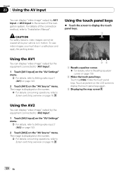
... menu. = For details, refer to Setting video input 2 (AV2) on page 143. 2 Touch [AV2] on the "AV Source" menu. For details of the navigation system. CAUTION For safety reasons, video images cannot be viewed while your vehicle is in a safe place and apply the parking brake. To view video images...page 18. 23 1 Recalls equalizer curves = For details, refer to Screen switching overview on the "AV Settings" menu. = For details, refer to "Installation Manual". Using the touch panel keys % Touch the screen to display the touch panel keys. 1 Using the AV1 You can display "video image" output by...
... menu. = For details, refer to Setting video input 2 (AV2) on page 143. 2 Touch [AV2] on the "AV Source" menu. For details of the navigation system. CAUTION For safety reasons, video images cannot be viewed while your vehicle is in a safe place and apply the parking brake. To view video images...page 18. 23 1 Recalls equalizer curves = For details, refer to Screen switching overview on the "AV Settings" menu. = For details, refer to "Installation Manual". Using the touch panel keys % Touch the screen to display the touch panel keys. 1 Using the AV1 You can display "video image" output by...


