Other Manual
Page 2
... front DVD or TV (sold separately) feature should never be in such a way that wires will not interfere with a rear view camera ...... 9 When connecting the external video component and the display 11 Attaching the noise filters 12 Installation 13 Installing the hide-away unit 13 DIN Front/Rear-mount 14 DIN Front-mount 14 DIN Rear-mount 15 Fixing the front panel 16 Installing the remote control unit 16...
... front DVD or TV (sold separately) feature should never be in such a way that wires will not interfere with a rear view camera ...... 9 When connecting the external video component and the display 11 Attaching the noise filters 12 Installation 13 Installing the hide-away unit 13 DIN Front/Rear-mount 14 DIN Front-mount 14 DIN Rear-mount 15 Fixing the front panel 16 Installing the remote control unit 16...

Other Manual
Page 3
...; The black lead is ground. Please ground this system, be installed in the electrical system, be sure to disconnect the ≠ battery cable before beginning installation. • Refer to the vehicle body. • Don't pass the yellow lead through a hole into the lead. Connect the connectors of the same colors correctly. • This unit cannot be sure not to connect the blue/white lead...
...; The black lead is ground. Please ground this system, be installed in the electrical system, be sure to disconnect the ≠ battery cable before beginning installation. • Refer to the vehicle body. • Don't pass the yellow lead through a hole into the lead. Connect the connectors of the same colors correctly. • This unit cannot be sure not to connect the blue/white lead...
Other Manual
Page 4
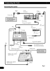
... (1 ft. 4 in.) 15 cm (5-7/8 in .) AV-BUS input (Blue) Black 21 pin cable (supplied) Auto-EQ&TA mic jack See the operation manual. IP-BUS cable Blue Multi-CD player (sold separately) Blue IP-BUS input (Blue) This product Violet 30 pin cable (supplied) 3 m (9 ft. 10 in.) 3 m (9 ft. 10 in.) Violet Antenna cable (supplied) 3 m (9 ft. 10 in.) Hide-away unit (supplied) Antenna jack Black Blue 10 cm (3-7/8 in.) 15 cm (5-7/8 in .) 26 pin cable Black Navigation unit (e.g.
... (1 ft. 4 in.) 15 cm (5-7/8 in .) AV-BUS input (Blue) Black 21 pin cable (supplied) Auto-EQ&TA mic jack See the operation manual. IP-BUS cable Blue Multi-CD player (sold separately) Blue IP-BUS input (Blue) This product Violet 30 pin cable (supplied) 3 m (9 ft. 10 in.) 3 m (9 ft. 10 in.) Violet Antenna cable (supplied) 3 m (9 ft. 10 in.) Hide-away unit (supplied) Antenna jack Black Blue 10 cm (3-7/8 in.) 15 cm (5-7/8 in .) 26 pin cable Black Navigation unit (e.g.

Other Manual
Page 5
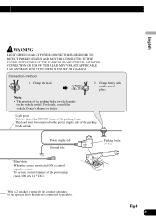
Connecting the power cord (1) English Español Deutsch Français Hide-away unit Fuse holder Yellow To terminal always supplied with power regardless of ignition switch position. Black ≠ Black/white + Center speaker Fig. 3 4 Italiano Nederlands Black (ground) To vehicle (metal) body.
Connecting the power cord (1) English Español Deutsch Français Hide-away unit Fuse holder Yellow To terminal always supplied with power regardless of ignition switch position. Black ≠ Black/white + Center speaker Fig. 3 4 Italiano Nederlands Black (ground) To vehicle (metal) body.

Other Manual
Page 6
... switch position. Violet/white Blue When the source is selected the tuner, a control signal is output. To Auto-antenna relay control terminal. Yellow To terminal always supplied with power regardless of any connections. Connecting the Units Connecting the power cord (2) See the section "When connecting with Mute function, wire this lead to the antenna booster power supply terminal (max. 300 mA 12 V DC). Yellow/black If you use an equipment with a rear view camera". Fuse holder This product Fuse resistor Fuse resistor Black (ground...
... switch position. Violet/white Blue When the source is selected the tuner, a control signal is output. To Auto-antenna relay control terminal. Yellow To terminal always supplied with power regardless of any connections. Connecting the Units Connecting the power cord (2) See the section "When connecting with Mute function, wire this lead to the antenna booster power supply terminal (max. 300 mA 12 V DC). Yellow/black If you use an equipment with a rear view camera". Fuse holder This product Fuse resistor Fuse resistor Black (ground...
Other Manual
Page 7
... the vehicle Owner's Manual or dealer. Power supply side Ground side Parking brake switch Blue/white When the source is switched ON, a control signal is output. To system control terminal of the parking brake switch depends on the vehicle model. Français Italiano Nederlands With a 2 speaker system, do not connect anything to the speaker leads that are not connected to the power supply side of the parking brake. Clamp the lead. 2. IMPROPER CONNECTION OR USE OF THIS...
... the vehicle Owner's Manual or dealer. Power supply side Ground side Parking brake switch Blue/white When the source is switched ON, a control signal is output. To system control terminal of the parking brake switch depends on the vehicle model. Français Italiano Nederlands With a 2 speaker system, do not connect anything to the speaker leads that are not connected to the power supply side of the parking brake. Clamp the lead. 2. IMPROPER CONNECTION OR USE OF THIS...

Other Manual
Page 8
See the section "Attaching the noise filters". 7 Connecting the Units When connecting to separately sold power amp Center output (CENTER OUTPUT) 23 cm (9 in.) This product Subwoofer output (SUBWOOFER OUTPUT) 23 cm (9 in.) Noise filter (small) Lock tie Rear output 15 cm (REAR OUTPUT) (5-7/8 in.) Front output (FRONT OUTPUT) 15 cm Blue/white (5-7/8 in.) When the source is switched ON, a control signal is output. To system control terminal of the power amp (max. 300 mA 12 V DC).
See the section "Attaching the noise filters". 7 Connecting the Units When connecting to separately sold power amp Center output (CENTER OUTPUT) 23 cm (9 in.) This product Subwoofer output (SUBWOOFER OUTPUT) 23 cm (9 in.) Noise filter (small) Lock tie Rear output 15 cm (REAR OUTPUT) (5-7/8 in.) Front output (FRONT OUTPUT) 15 cm Blue/white (5-7/8 in.) When the source is switched ON, a control signal is output. To system control terminal of the power amp (max. 300 mA 12 V DC).

Other Manual
Page 9
Fig. 5 8 Nederlands English Español RCA cables (sold separately) Power amp (sold separately) Power amp (sold separately) Power amp (sold separately) Power amp (sold separately) Deutsch Français Italiano System remote control Left Front speaker Right Front speaker Rear speaker Rear speaker Subwoofer Center speaker Perform these connections when using the optional amplifier.
Fig. 5 8 Nederlands English Español RCA cables (sold separately) Power amp (sold separately) Power amp (sold separately) Power amp (sold separately) Power amp (sold separately) Deutsch Français Italiano System remote control Left Front speaker Right Front speaker Rear speaker Rear speaker Subwoofer Center speaker Perform these connections when using the optional amplifier.
Other Manual
Page 10
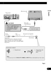
WARNING: • USE INPUT ONLY FOR REVERSE OR MIRROR IMAGE REAR VIEW CAMERA. Connecting the Units When connecting with a rear view camera When using this product with a rear view camera, automatic switching to video from a rear view camera when the gear shift is moved to REVERSE (R) position is to use this product as an aid to keep an eye on trailers, or backing into a tight parking spot. CAUTION: • The screen image may appear closer or more distant than in...
WARNING: • USE INPUT ONLY FOR REVERSE OR MIRROR IMAGE REAR VIEW CAMERA. Connecting the Units When connecting with a rear view camera When using this product with a rear view camera, automatic switching to video from a rear view camera when the gear shift is moved to REVERSE (R) position is to use this product as an aid to keep an eye on trailers, or backing into a tight parking spot. CAUTION: • The screen image may appear closer or more distant than in...
Other Manual
Page 11
...-away unit Español Deutsch Français CAUTION Pioneer recommends the use of a camera which the voltage changes when the gear shift is necessary to set to the back lamp, connect the one in which outputs mirror reversed images, otherwise screen image may appear reversed. Clamp the lead. 2. Note: • It is in SETUP when connecting the rear view camera. Clamp firmly with needle-nosed pliers. Fuse resistor Connection method...
...-away unit Español Deutsch Français CAUTION Pioneer recommends the use of a camera which the voltage changes when the gear shift is necessary to set to the back lamp, connect the one in which outputs mirror reversed images, otherwise screen image may appear reversed. Clamp the lead. 2. Note: • It is in SETUP when connecting the rear view camera. Clamp firmly with needle-nosed pliers. Fuse resistor Connection method...
Other Manual
Page 12
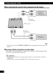
... with RCA input jacks To video input Fig. 7 • It is for connection of a display to enable passengers in a location that enables the Driver to AV INPUT in SETUP when connecting the external video com- When using a display connected to rear video output This product's rear video output is necessary to set to watch the DVD or Video CD. Connecting the Units When connecting the external video component and the display To audio outputs To video output External video component (sold separately) RCA cables (sold separately) Hide-away unit RCA cables (sold separately power amp...
... with RCA input jacks To video input Fig. 7 • It is for connection of a display to enable passengers in a location that enables the Driver to AV INPUT in SETUP when connecting the external video com- When using a display connected to rear video output This product's rear video output is necessary to set to watch the DVD or Video CD. Connecting the Units When connecting the external video component and the display To audio outputs To video output External video component (sold separately) RCA cables (sold separately) Hide-away unit RCA cables (sold separately power amp...

Other Manual
Page 13
This product Noise filter (large) Lock tie Other than speaker leads Noise filter (large) Noise filter (small) Lock tie Speaker leads Hide-away unit Lock tie Noise filter (large) Deutsch Français Italiano Noise filter (small) Noise filter (large) Lock tie Noise filter (large) Lock tie Fig. 8 12 Nederlands English Español Attaching the noise filters To prevent the noise, use the supplied noise filters correctly.
This product Noise filter (large) Lock tie Other than speaker leads Noise filter (large) Noise filter (small) Lock tie Speaker leads Hide-away unit Lock tie Noise filter (large) Deutsch Français Italiano Noise filter (small) Noise filter (large) Lock tie Noise filter (large) Lock tie Fig. 8 12 Nederlands English Español Attaching the noise filters To prevent the noise, use the supplied noise filters correctly.
Other Manual
Page 14
... there is installed under a front seat, make sure none of unauthorized parts can cause malfunctions. • Consult with your vehicle's air bags. • The semiconductor laser will impede the driver's visibility or affect the operation of your nearest dealer if installation requires the drilling of the unit, temporarily connect the wiring to ensure proper installation. Route all leads and cords carefully...
... there is installed under a front seat, make sure none of unauthorized parts can cause malfunctions. • Consult with your vehicle's air bags. • The semiconductor laser will impede the driver's visibility or affect the operation of your nearest dealer if installation requires the drilling of the unit, temporarily connect the wiring to ensure proper installation. Route all leads and cords carefully...
Other Manual
Page 15
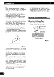
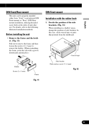
... parts that protrude from "Front" (conventional DIN Front-mount) or "Rear" (DIN Rearmount installation, utilizing threaded screw holes at the sides of side brackets. Conceal tape Side bracket Flush surface screw (5 × 6 mm) Fig. 12 Deutsch Français Italiano Nederlands 14 English Español DIN Front/Rear-mount This unit can be properly installed...
... parts that protrude from "Front" (conventional DIN Front-mount) or "Rear" (DIN Rearmount installation, utilizing threaded screw holes at the sides of side brackets. Conceal tape Side bracket Flush surface screw (5 × 6 mm) Fig. 12 Deutsch Français Italiano Nederlands 14 English Español DIN Front/Rear-mount This unit can be properly installed...
Other Manual
Page 16
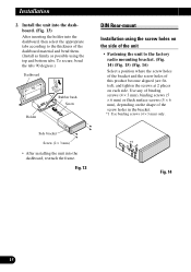
Side bracket Screw (2 × 3 mm) • After installing the unit into the dashboard, then select the appropriate tabs according to the factory radio mounting bracket. (Fig. 14) (Fig. 15) (Fig. 16) Select a position where the screw holes of the bracket and the screw ... Screw Holder DIN Rear-mount Installation using the top and bottom tabs. Fig. 13 *1 *1 Fig. 14 15 Install the unit into the dashboard. (Fig. 13) After inserting the holder into the dashboard, reattach the frame. Use any of the dashboard material and bend them. (Install as firmly as possible using the screw holes...
Side bracket Screw (2 × 3 mm) • After installing the unit into the dashboard, then select the appropriate tabs according to the factory radio mounting bracket. (Fig. 14) (Fig. 15) (Fig. 16) Select a position where the screw holes of the bracket and the screw ... Screw Holder DIN Rear-mount Installation using the top and bottom tabs. Fig. 13 *1 *1 Fig. 14 15 Install the unit into the dashboard. (Fig. 13) After inserting the holder into the dashboard, reattach the frame. Use any of the dashboard material and bend them. (Install as firmly as possible using the screw holes...
Other Manual
Page 17
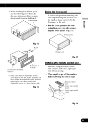
... 2 places on parts that protrude from moving. • Thoroughly wipe off the surface before affixing the velcro tape. Remote control unit Velcro tape (small) (hard) Velcro tape (small) (soft) Fig. 18 Français Italiano Nederlands 16 Conceal tape *1 *1 Fixing the front panel If you do not operate the removing and attaching the front panel function, use the following screw...
... 2 places on parts that protrude from moving. • Thoroughly wipe off the surface before affixing the velcro tape. Remote control unit Velcro tape (small) (hard) Velcro tape (small) (soft) Fig. 18 Français Italiano Nederlands 16 Conceal tape *1 *1 Fixing the front panel If you do not operate the removing and attaching the front panel function, use the following screw...

Other Manual
Page 34
...B-9120 Melsele, Belgium TEL: (0) 3/570.05.11 PIONEER ELECTRONICS ASIACENTRE PTE. Copyright © 2004 Pioneer Corporation. LTD. 253 Alexandra Road, #04-01, Singapore 159936 TEL: 65-6472-7555 PIONEER ELECTRONICS AUSTRALIA PTY. de C.V. Copyright © 2004 by Pioneer Corporation. LTD. 178-184 Boundary Road, Braeside, Victoria... Camacho 138 10 piso Col.Lomas de Chapultepec, Mexico, D.F. 11000 TEL: 55-9178-4270 Published by Pioneer Corporation. Tous droits de reproduction et de traduction réservés. Box 1540, Long Beach, California 90801-1540, U.S.A. Publication de...
...B-9120 Melsele, Belgium TEL: (0) 3/570.05.11 PIONEER ELECTRONICS ASIACENTRE PTE. Copyright © 2004 Pioneer Corporation. LTD. 253 Alexandra Road, #04-01, Singapore 159936 TEL: 65-6472-7555 PIONEER ELECTRONICS AUSTRALIA PTY. de C.V. Copyright © 2004 by Pioneer Corporation. LTD. 178-184 Boundary Road, Braeside, Victoria... Camacho 138 10 piso Col.Lomas de Chapultepec, Mexico, D.F. 11000 TEL: 55-9178-4270 Published by Pioneer Corporation. Tous droits de reproduction et de traduction réservés. Box 1540, Long Beach, California 90801-1540, U.S.A. Publication de...


