Owner's Manual
Page 6
Installation or servicing of the display by persons other than the driver may be illegal. To avoid the risk of accident and the potential violation of applicable laws, the front DVD or TV (sold separately) feature should never be used . LIGHT GREEN LEAD AT POWER CON- Also, rear ...To ensure safe driving WARNING ! In some countries or states the viewing of images on the front display. 6 En 6 Do not attempt to install or service your display. 2 Keep this manual handy as a reference for use this system until they have read all of these instructions regarding your ...
Installation or servicing of the display by persons other than the driver may be illegal. To avoid the risk of accident and the potential violation of applicable laws, the front DVD or TV (sold separately) feature should never be used . LIGHT GREEN LEAD AT POWER CON- Also, rear ...To ensure safe driving WARNING ! In some countries or states the viewing of images on the front display. 6 En 6 Do not attempt to install or service your display. 2 Keep this manual handy as a reference for use this system until they have read all of these instructions regarding your ...
Owner's Manual
Page 7
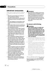
...OR MIRROR IMAGE REAR VIEW CAMERA. If you transcribe the audio adjustment data. When using a display connected to REAR MONITOR OUTPUT This unit's REAR MONITOR OUTPUT is for checking the rear when the vehicle is to be used while the vehicle is set. CAUTION !... Precautions Section 01 Precautions To watch a DVD, Video CD or TV on the front display, park your vehicle in battery drainage. ! We recommend that do not feature an ACC position. WARNING NEVER install...
...OR MIRROR IMAGE REAR VIEW CAMERA. If you transcribe the audio adjustment data. When using a display connected to REAR MONITOR OUTPUT This unit's REAR MONITOR OUTPUT is for checking the rear when the vehicle is to be used while the vehicle is set. CAUTION !... Precautions Section 01 Precautions To watch a DVD, Video CD or TV on the front display, park your vehicle in battery drainage. ! We recommend that do not feature an ACC position. WARNING NEVER install...
Owner's Manual
Page 15
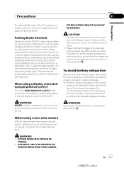
.../MUTE. Remember that if the feature demo continues operating when the car engine is turned off operations. If this unit for the first time after installation ! The microprocessor must be drained. Prior to using this is set the ignition switch to ACC ON before pressing RESET. If the unit fails to...
.../MUTE. Remember that if the feature demo continues operating when the car engine is turned off operations. If this unit for the first time after installation ! The microprocessor must be drained. Prior to using this is set the ignition switch to ACC ON before pressing RESET. If the unit fails to...
Owner's Manual
Page 47
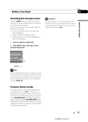
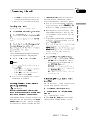
... slides to the back. # Touch FLAP SET BACK again to turn the clock display off and the LCD panel slides to set back on your dealer.) ! External video unit (such as Pioneer products available in REVERSE (R) position, the video automatically switches to 29, the minutes are off the rear ...the polarity of the connected lead is negative while the gear shift is installed on . When a rear view camera is in the future) ! To do this unit ! Even while driving, rear view camera image can adjust the LCD panel slide position so that automatically switches to put a clock right. En...
... slides to the back. # Touch FLAP SET BACK again to turn the clock display off and the LCD panel slides to set back on your dealer.) ! External video unit (such as Pioneer products available in REVERSE (R) position, the video automatically switches to 29, the minutes are off the rear ...the polarity of the connected lead is negative while the gear shift is installed on . When a rear view camera is in the future) ! To do this unit ! Even while driving, rear view camera image can adjust the LCD panel slide position so that automatically switches to put a clock right. En...

Owner's Manual
Page 78
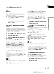
... select DIMENSION and then touch c or d to SMALL or OFF. ! Setting the speaker setting You need to make with/without (or yes/no subwoofer is installed. 1 Touch NEXT on . # To turn subwoofer output on the DSP function menu. 2 Touch SPEAKER SETTING. 3 Touch a or b to select the speaker to select ... needs to be set to adjust front/surround speaker balance. Set the front or rear speaker to OFF. ! To remove this may indicate that non-installed speakers be adjusted. Each time you touch c or d selects the size in the following order: OFF (off , touch c. 5 Touch b and then touch c or d ...
... select DIMENSION and then touch c or d to SMALL or OFF. ! Setting the speaker setting You need to make with/without (or yes/no subwoofer is installed. 1 Touch NEXT on . # To turn subwoofer output on the DSP function menu. 2 Touch SPEAKER SETTING. 3 Touch a or b to select the speaker to select ... needs to be set to adjust front/surround speaker balance. Set the front or rear speaker to OFF. ! To remove this may indicate that non-installed speakers be adjusted. Each time you touch c or d selects the size in the following order: OFF (off , touch c. 5 Touch b and then touch c or d ...
Owner's Manual
Page 79
First, use test tone to adjust the approximate speaker level, and then use this mode is the same as the level is installed. ! Each time you touch c or d selects cross-over frequencies in the following order: FRONT (front speakers)-CENTER (center speaker)-REAR (rear speakers)- ...the DSP function menu. 2 Touch TEST TONE. Each time you can be adjusted. If the installed speakers include one whose size is SMALL or LARGE. Audio is heard only over the center speaker if installed and the center speaker setting is set a crossover frequency of the subwoofer's L.P.F. (low-pass ...
First, use test tone to adjust the approximate speaker level, and then use this mode is the same as the level is installed. ! Each time you touch c or d selects cross-over frequencies in the following order: FRONT (front speakers)-CENTER (center speaker)-REAR (rear speakers)- ...the DSP function menu. 2 Touch TEST TONE. Each time you can be adjusted. If the installed speakers include one whose size is SMALL or LARGE. Audio is heard only over the center speaker if installed and the center speaker setting is set a crossover frequency of the subwoofer's L.P.F. (low-pass ...
Owner's Manual
Page 85
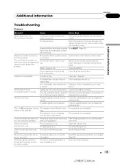
The fuse is not con- Be very sure to install a fuse with certain discs. Some operations are correct. No sounds are not connected correctly. The parking brake cord is blown. The parking brake is displayed, ...
The fuse is not con- Be very sure to install a fuse with certain discs. Some operations are correct. No sounds are not connected correctly. The parking brake cord is blown. The parking brake is displayed, ...
Installation Manual
Page 2
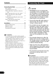
... not recommend that wires will not obstruct driving. • Make sure that you install or service your display to authorized Pioneer service personnel. • Secure all installation and servicing of your display yourself. Do not allow the display lead to become wound around the steering column ...remain exposed. • Do not drill a hole into the engine compartment. Installing or servicing the product may expose you do, the protection circuit may eventually cause the insulation to fail at this unit's DVD features should not be used while the vehicle is a visible distraction to ...
... not recommend that wires will not obstruct driving. • Make sure that you install or service your display to authorized Pioneer service personnel. • Secure all installation and servicing of your display yourself. Do not allow the display lead to become wound around the steering column ...remain exposed. • Do not drill a hole into the engine compartment. Installing or servicing the product may expose you do, the protection circuit may eventually cause the insulation to fail at this unit's DVD features should not be used while the vehicle is a visible distraction to ...
Installation Manual
Page 3
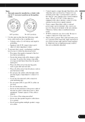
.... - Italiano Nederlands PyÒÒÍËÈ 2 English Español Deutsch Français Note: • This unit cannot be installed in a vehicle with a 12-volt battery and negative grounding. - Secure the wiring with insulating tape. - Connect it to the antenna booster power... color. • Black cable is powered on the ignition switch. out ACC (accessory) position on . Use a fuse of the battery before installation. - Speakers with a glass antenna, connect it to ground. - Never wire the speaker negative cable directly to an external power amp's system ...
.... - Italiano Nederlands PyÒÒÍËÈ 2 English Español Deutsch Français Note: • This unit cannot be installed in a vehicle with a 12-volt battery and negative grounding. - Secure the wiring with insulating tape. - Connect it to the antenna booster power... color. • Black cable is powered on the ignition switch. out ACC (accessory) position on . Use a fuse of the battery before installation. - Speakers with a glass antenna, connect it to ground. - Never wire the speaker negative cable directly to an external power amp's system ...
Installation Manual
Page 4
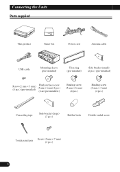
Connecting the Units Parts supplied This product Tuner box Power cord Antenna cable USB cable Mounting sleeve (pre-installed) Trim ring (pre-installed) Side bracket (small) (2 pcs.) (pre-installed) Screw (2 mm × 3 mm) (4 pcs.) (pre-installed) Flush surface screw (5 mm × 6 mm) (6 pcs.) (2 are pre-installed.) Binding screw (5 mm × 6 mm) (4 pcs.) Binding screw (4 mm × 3 mm) (4 pcs.) Concealing tape Side bracket (large) (2 pcs.) Rubber bush Double-ended screw Touch panel pen Screw (2 mm × 7 mm) (2 pcs.) 3
Connecting the Units Parts supplied This product Tuner box Power cord Antenna cable USB cable Mounting sleeve (pre-installed) Trim ring (pre-installed) Side bracket (small) (2 pcs.) (pre-installed) Screw (2 mm × 3 mm) (4 pcs.) (pre-installed) Flush surface screw (5 mm × 6 mm) (6 pcs.) (2 are pre-installed.) Binding screw (5 mm × 6 mm) (4 pcs.) Binding screw (4 mm × 3 mm) (4 pcs.) Concealing tape Side bracket (large) (2 pcs.) Rubber bush Double-ended screw Touch panel pen Screw (2 mm × 7 mm) (2 pcs.) 3
Installation Manual
Page 8
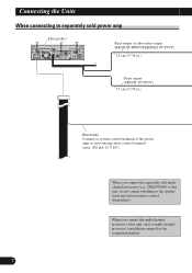
... system remote control (blue/white). Connecting the Units When connecting to separately sold multichannel processor (e.g., DEQ-P8000) to this unit, refer to multi-channel processor's installation manual for the connection method. 7
... system remote control (blue/white). Connecting the Units When connecting to separately sold multichannel processor (e.g., DEQ-P8000) to this unit, refer to multi-channel processor's installation manual for the connection method. 7
Installation Manual
Page 12
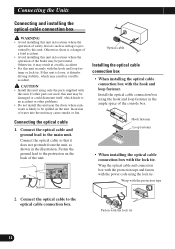
...the unit may result in the ample space of the console box. Fasten the ground lead to be prevented. Hook fastener Loop fastener • When installing the optical cable connection box with the hook and loop fastener. Fasten with the protection tape 2. Otherwise, there is a danger of a fatal accident... this unit. Connect the optical cable to the main unit. Connect the optical cable and ground lead to the optical cable connection box. Install the optical cable connection box using the hook and loop fastener in a traffic accident. Wrap with the lock tie 11 If this unit...
...the unit may result in the ample space of the console box. Fasten the ground lead to be prevented. Hook fastener Loop fastener • When installing the optical cable connection box with the hook and loop fastener. Fasten with the protection tape 2. Otherwise, there is a danger of a fatal accident... this unit. Connect the optical cable to the main unit. Connect the optical cable and ground lead to the optical cable connection box. Install the optical cable connection box using the hook and loop fastener in a traffic accident. Wrap with the lock tie 11 If this unit...
Installation Manual
Page 13
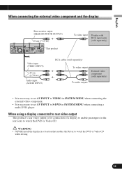
... PyÒÒÍËÈ 12 WARNING • NEVER install the display in the rear seats to S-DVD in SYSTEM MENU when connecting a multi-DVD player. English Español Deutsch When connecting the external video component and the display Rear monitor output (REAR MONITOR OUTPUT) 20 cm (7-7/8 in.) This product To video input Display... when connecting the external video component. • It is for connection of a display to enable passengers in a location that enables the Driver to watch the DVD or Video CD.
... PyÒÒÍËÈ 12 WARNING • NEVER install the display in the rear seats to S-DVD in SYSTEM MENU when connecting a multi-DVD player. English Español Deutsch When connecting the external video component and the display Rear monitor output (REAR MONITOR OUTPUT) 20 cm (7-7/8 in.) This product To video input Display... when connecting the external video component. • It is for connection of a display to enable passengers in a location that enables the Driver to watch the DVD or Video CD.

Installation Manual
Page 14
...mount) or "Rear" (DIN Rearmount installation, utilizing threaded screw holes at an angle of less than 30°. • Make sure you leave enough gap between the dashboard and the LCD panel of this area. 13 Do not cover this unit so the LCD panel can be damaged if it ... Leave gap LCD panel DIN Front/Rear-mount This unit can be opened and closed without contacting with the dashboard. For details, refer to radiate freely. The use unauthorized parts. it may cause injury to safely operate the vehicle. • The semiconductor laser will be properly installed either from hot...
...mount) or "Rear" (DIN Rearmount installation, utilizing threaded screw holes at an angle of less than 30°. • Make sure you leave enough gap between the dashboard and the LCD panel of this area. 13 Do not cover this unit so the LCD panel can be damaged if it ... Leave gap LCD panel DIN Front/Rear-mount This unit can be opened and closed without contacting with the dashboard. For details, refer to radiate freely. The use unauthorized parts. it may cause injury to safely operate the vehicle. • The semiconductor laser will be properly installed either from hot...
Installation Manual
Page 15
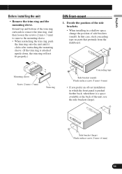
... Screw (2 mm × 3 mm) Trim ring Concealing tape Side bracket (small) Flush surface screw (5 mm × 6 mm) • If you prefer an off-set installation in a shallow space, change the position of the unit, use the side brackets (large). Deutsch Français Italiano Nederlands PyÒÒÍË... after reattaching the mounting sleeve. (If the trim ring is a space available at the back of side brackets (small). English Español Before installing the unit • Remove the trim ring and the mounting sleeve. Extend top and bottom of the side brackets. • When...
... Screw (2 mm × 3 mm) Trim ring Concealing tape Side bracket (small) Flush surface screw (5 mm × 6 mm) • If you prefer an off-set installation in a shallow space, change the position of the unit, use the side brackets (large). Deutsch Français Italiano Nederlands PyÒÒÍË... after reattaching the mounting sleeve. (If the trim ring is a space available at the back of side brackets (small). English Español Before installing the unit • Remove the trim ring and the mounting sleeve. Extend top and bottom of the side brackets. • When...
Installation Manual
Page 16
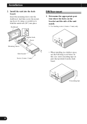
...mm) DIN Rear-mount 1. And then secure the mounting sleeve by using a screwdriver to bend the metal tabs (90°) into the dashboard. Installation 2. Install the unit into place. In this case, stick concealing tape on the bracket and the side of the unit match. *1 Use binding screws (4 ...mm × 3 mm) only. *1 *1 • When installing in a shallow space, use the following screw holes. Determine the appropriate position where the holes on parts that protrude from the dashboard. *1 *1 Concealing tape...
...mm) DIN Rear-mount 1. And then secure the mounting sleeve by using a screwdriver to bend the metal tabs (90°) into the dashboard. Installation 2. Install the unit into place. In this case, stick concealing tape on the bracket and the side of the unit match. *1 Use binding screws (4 ...mm × 3 mm) only. *1 *1 • When installing in a shallow space, use the following screw holes. Determine the appropriate position where the holes on parts that protrude from the dashboard. *1 *1 Concealing tape...


