Owner's Manual
Page 6
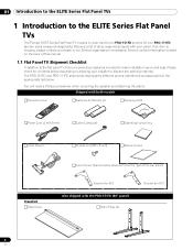
... to the top right of this manual. 1.1 Flat Panel TV Shipment Checklist In addition to the flat panel TV, there are several accessories included to the ELITE Series Flat Panel TVs The Pioneer ELITE Series Flat Panel TV models include the 60-inch PRO-151FD and the 50-inch PRO-111FD (screen sizes measured diagonally). You will need a Philips...
... to the top right of this manual. 1.1 Flat Panel TV Shipment Checklist In addition to the flat panel TV, there are several accessories included to the ELITE Series Flat Panel TVs The Pioneer ELITE Series Flat Panel TV models include the 60-inch PRO-151FD and the 50-inch PRO-111FD (screen sizes measured diagonally). You will need a Philips...
Owner's Manual
Page 7
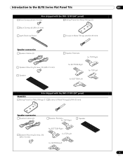
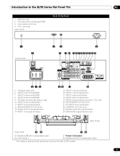
Introduction to the ELITE Series Flat Panel TVs 01 Also shipped with the PRO-151FD (60" panel) Silver Screws (4) (4×10 mm) Falling Prevention Metal Fittings (2) Black Screws (4) (M6×20 mm) Light-Blocking Shield Screws to Metal Fittings (4) (M4×... Screws (16) (M5×10 mm) Speaker Speaker Brackets for TOP-Right for BOTTOM-Right for TOP-Left for BOTTOM-Left Also shipped with the PRO-111FD (50" panel) Stand kit Falling Prevention Metal Fittings (2) Screws to Metal Fittings(2) (M4×35 mm) Speaker accessories Speaker Cables (2) Speaker Brackets for TOP...
Introduction to the ELITE Series Flat Panel TVs 01 Also shipped with the PRO-151FD (60" panel) Silver Screws (4) (4×10 mm) Falling Prevention Metal Fittings (2) Black Screws (4) (M6×20 mm) Light-Blocking Shield Screws to Metal Fittings (4) (M4×... Screws (16) (M5×10 mm) Speaker Speaker Brackets for TOP-Right for BOTTOM-Right for TOP-Left for BOTTOM-Left Also shipped with the PRO-111FD (50" panel) Stand kit Falling Prevention Metal Fittings (2) Screws to Metal Fittings(2) (M4×35 mm) Speaker accessories Speaker Cables (2) Speaker Brackets for TOP...
Owner's Manual
Page 8
... functions. SLEEP indicator Command Side of Panel 6 (PRO-111FD) 1 23 1 - The following sections provide button locations/operations for the panel and the remote control. 1.2.1 Control Buttons and More on the Flat Panel TV Your flat panel TV has buttons, indicators, and sensors on the panel ...can operate your flat panel TV from the panel buttons or with more buttons, toggles, and ports on the lower front bezel with the remote control. Power ON indicator 2 - STANDBY indicator 3 - ELITE Series Models: Face of the Panel (left side) 8 13 14 9 15 (PRO-151FD) 1 23 45 7 4...
... functions. SLEEP indicator Command Side of Panel 6 (PRO-111FD) 1 23 1 - The following sections provide button locations/operations for the panel and the remote control. 1.2.1 Control Buttons and More on the Flat Panel TV Your flat panel TV has buttons, indicators, and sensors on the panel ...can operate your flat panel TV from the panel buttons or with more buttons, toggles, and ports on the lower front bezel with the remote control. Power ON indicator 2 - STANDBY indicator 3 - ELITE Series Models: Face of the Panel (left side) 8 13 14 9 15 (PRO-151FD) 1 23 45 7 4...
Owner's Manual
Page 9
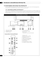
...IR REPEATER OUT terminal 21 -PC INPUT terminal (Audio) 22 -CONTROL OUT terminal 23 -DIGITAL OUT terminal (Optical) 24 -SPEAKERS (right/left) terminal (PRO-151FD) (lower bank) 25 26 27 28 25 -Speakers (R) terminal (speaker side) 26 -Color Sensor 27 -Power On button 28 -Speakers (L) terminal (speaker... side) Terminals on side and rear panels are common to the ELITE Series Flat Panel TVs 01 1 - INPUT 5 terminal (HDMI) 8 - RC-232C terminal (for factory use) 10 - Ethernet cable port 6 - AC In terminal (upper bank) ...
...IR REPEATER OUT terminal 21 -PC INPUT terminal (Audio) 22 -CONTROL OUT terminal 23 -DIGITAL OUT terminal (Optical) 24 -SPEAKERS (right/left) terminal (PRO-151FD) (lower bank) 25 26 27 28 25 -Speakers (R) terminal (speaker side) 26 -Color Sensor 27 -Power On button 28 -Speakers (L) terminal (speaker... side) Terminals on side and rear panels are common to the ELITE Series Flat Panel TVs 01 1 - INPUT 5 terminal (HDMI) 8 - RC-232C terminal (for factory use) 10 - Ethernet cable port 6 - AC In terminal (upper bank) ...
Owner's Manual
Page 14
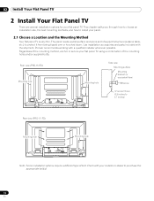
... or secure your panel. 2.1 Choose a Location and the Mounting Method Your flat panel TV is very thin. Pioneer recommends working with the shipment. Regardless of bolt. Use installation accessories and parts included with a qualified installer whenever possible. Rear view (PRO-151FD) Mounting hole Mounting hole Side view Mounting surface Mounting bracket (or equivalent item...
... or secure your panel. 2.1 Choose a Location and the Mounting Method Your flat panel TV is very thin. Pioneer recommends working with the shipment. Regardless of bolt. Use installation accessories and parts included with a qualified installer whenever possible. Rear view (PRO-151FD) Mounting hole Mounting hole Side view Mounting surface Mounting bracket (or equivalent item...
Owner's Manual
Page 16
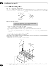
... up. 5 ) Insert the stand supports (legs) into the base cover. Refer to the panel for assistance. 2 ) Lay the flat panel TV down on page 19 for the PRO-151FD. If you are in to avoid scratching. Attach the included stand to "Attach/Detach the Speaker" on a raised surface with the... Pioneer table top stand (stand) attached. If you are mounting the PRO-111FD skip to Step 7. 4 ) Turn the base cover over the edge. 3 ) Place all stand parts on a wagon or pallet that they are mounting the PRO-151FD continue with a soft sheet placed under ...
... up. 5 ) Insert the stand supports (legs) into the base cover. Refer to the panel for assistance. 2 ) Lay the flat panel TV down on page 19 for the PRO-151FD. If you are in to avoid scratching. Attach the included stand to "Attach/Detach the Speaker" on a raised surface with the... Pioneer table top stand (stand) attached. If you are mounting the PRO-111FD skip to Step 7. 4 ) Turn the base cover over the edge. 3 ) Place all stand parts on a wagon or pallet that they are mounting the PRO-151FD continue with a soft sheet placed under ...
Owner's Manual
Page 17
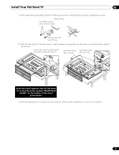
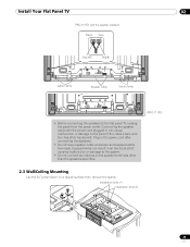
... the stand, attach the falling prevention metal fittings using the installation screws. (PRO-151FD) Installation screws (M4 x 35 mm: black) Falling prevention metal fitting 8 ) With the flat panel TV still face down, insert the stand's supports into the flat panel TV so that the arrow marked "FRONT/FACE AVANT" on the bottom of the... then tighten the screws. Installation bolts (M6 x 20 mm) Installation bolts (M6 x 20 mm) Insert the stand supports into the bottom of the flat panel TV.
... the stand, attach the falling prevention metal fittings using the installation screws. (PRO-151FD) Installation screws (M4 x 35 mm: black) Falling prevention metal fitting 8 ) With the flat panel TV still face down, insert the stand's supports into the flat panel TV so that the arrow marked "FRONT/FACE AVANT" on the bottom of the... then tighten the screws. Installation bolts (M6 x 20 mm) Installation bolts (M6 x 20 mm) Insert the stand supports into the bottom of the flat panel TV.
Owner's Manual
Page 19
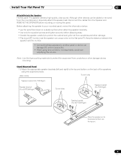
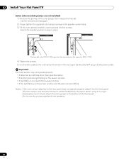
... damage. • Placing a CRT monitor near the speaker can damage the unit or cause a fire. • When using the supplied screws. (PRO-151FD) Screw holes Speaker bracket (For TOP-Right) Speaker bracket (For BOTTOM-Right) Screw holes Speaker bracket (For TOP-Right) Speaker bracket (For BOTTOM-Right...panel or device can cause a blur on the back of the speakers using tone control to the top and bottom on the flat panel TV. Stand-Mounted Panel 1 ) Attach the appropriate speaker brackets (left and right) to increase treble, avoid overamplifying the volume. Keep the ...
... damage. • Placing a CRT monitor near the speaker can damage the unit or cause a fire. • When using the supplied screws. (PRO-151FD) Screw holes Speaker bracket (For TOP-Right) Speaker bracket (For BOTTOM-Right) Screw holes Speaker bracket (For TOP-Right) Speaker bracket (For BOTTOM-Right...panel or device can cause a blur on the back of the speakers using tone control to the top and bottom on the flat panel TV. Stand-Mounted Panel 1 ) Attach the appropriate speaker brackets (left and right) to increase treble, avoid overamplifying the volume. Keep the ...
Owner's Manual
Page 20
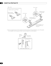
Do not tighten it loose, with about 5 mm 20 En Speaker mounting hole Top, rear of flat panel TV Top of flat panel TV 5 mm Leave a space of the panel. Leave it all the way yet. 02 Install Your Flat Panel TV (PRO-111FD) Speaker bracket (For TOP-Right) Speaker bracket (For BOTTOM-Right) Screw holes Screw holes Speaker bracket (For TOP-Right) Speaker bracket (For BOTTOM-Right) Place the speaker so its terminals (bottom) are facing you. 2 ) Screw a supplied screw into the speaker bracket hole (lower of the two) at the top, rear of about 5 mm left to tighten.
Do not tighten it loose, with about 5 mm 20 En Speaker mounting hole Top, rear of flat panel TV Top of flat panel TV 5 mm Leave a space of the panel. Leave it all the way yet. 02 Install Your Flat Panel TV (PRO-111FD) Speaker bracket (For TOP-Right) Speaker bracket (For BOTTOM-Right) Screw holes Screw holes Speaker bracket (For TOP-Right) Speaker bracket (For BOTTOM-Right) Place the speaker so its terminals (bottom) are facing you. 2 ) Screw a supplied screw into the speaker bracket hole (lower of the two) at the top, rear of about 5 mm left to tighten.
Owner's Manual
Page 21
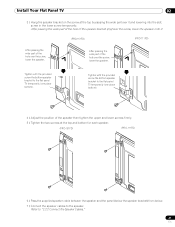
...of the speaker then tighten the upper and lower screws firmly. 5 ) Tighten the two screws at the top by passing the wide part over it . (PRO-151FD) (PRO-111FD) After passing the wide part of the hole over the screw, lower the speaker. After passing the wide part of the hole of the...) over the screw, lower the speaker onto it and lowering into the slot; Install Your Flat Panel TV 02 3 ) Hang the speaker bracket on the screw at the top and bottom for each speaker. (PRO-151FD) (PRO-111FD) 6 ) Pass the supplied speaker cable between the speaker and the panel (below the speaker bracket) ...
...of the speaker then tighten the upper and lower screws firmly. 5 ) Tighten the two screws at the top by passing the wide part over it . (PRO-151FD) (PRO-111FD) After passing the wide part of the hole over the screw, lower the speaker. After passing the wide part of the hole of the...) over the screw, lower the speaker onto it and lowering into the slot; Install Your Flat Panel TV 02 3 ) Hang the speaker bracket on the screw at the top and bottom for each speaker. (PRO-151FD) (PRO-111FD) 6 ) Pass the supplied speaker cable between the speaker and the panel (below the speaker bracket) ...
Owner's Manual
Page 22
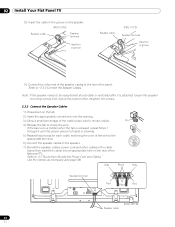
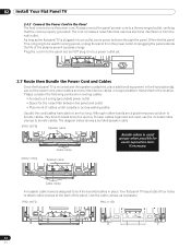
... ) Press down on the tab. 2 ) Insert the appropriately colored wire into an appropriate hole on the speaker. (PRO-151FD) Speaker cable Speaker terminal Insertion in groove Speaker cable (PRO-111FD) Speaker terminal Insertion in groove 9 ) Connect the other cables in the cable clamp then insert the clamp into the... the groove on the rear of the flat panel TV. Refer to clamp the wire. tab 4 ) Release the tab to "2.7 Route then Bundle the Power Cord and Cables." Gray Black Gray Speaker terminal Red Black Red Speaker cable (PRO-151FD) 22 En Note: If the speaker needs to ...
... ) Press down on the tab. 2 ) Insert the appropriately colored wire into an appropriate hole on the speaker. (PRO-151FD) Speaker cable Speaker terminal Insertion in groove Speaker cable (PRO-111FD) Speaker terminal Insertion in groove 9 ) Connect the other cables in the cable clamp then insert the clamp into the... the groove on the rear of the flat panel TV. Refer to clamp the wire. tab 4 ) Release the tab to "2.7 Route then Bundle the Power Cord and Cables." Gray Black Gray Speaker terminal Red Black Red Speaker cable (PRO-151FD) 22 En Note: If the speaker needs to ...
Owner's Manual
Page 23
Installation bolts (1) Installation bolts (2) 23 En Install Your Flat Panel TV 02 PRO-151FD with the power cord plugged in the power cord after connecting the speakers. • Do not leave speaker cable wires bare and exposed at the .... Plug in can result in an electrical short causing malfunction or damage to the system. • Do not connect any devices to the flat panel TV, unplug the panel from the power outlet. Exposed wires can cause malfunction or damage to the panel if the cable's bare wire touches other than...
Installation bolts (1) Installation bolts (2) 23 En Install Your Flat Panel TV 02 PRO-151FD with the power cord plugged in the power cord after connecting the speakers. • Do not leave speaker cable wires bare and exposed at the .... Plug in can result in an electrical short causing malfunction or damage to the system. • Do not connect any devices to the flat panel TV, unplug the panel from the power outlet. Exposed wires can cause malfunction or damage to the panel if the cable's bare wire touches other than...
Owner's Manual
Page 24
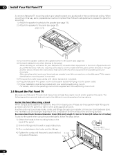
... on a location for the different mounting and anchoring options. requires some preparations must be completed first. 02 Install Your Flat Panel TV A common flat panel TV mounting option is to communicate with the panel, either directly or through your installer or from your local hardware store. Anchor the... panel for mounting. 1 ) Attach the speaker brackets to the speaker (see page 19). 2 ) Attach the speaker to the panel (see page 21). (PRO-111FD) 3 ) Connect the speaker cables to the speakers then to the panel (see page 22). 4 ) Connect cables for any other devices to a wall...
... on a location for the different mounting and anchoring options. requires some preparations must be completed first. 02 Install Your Flat Panel TV A common flat panel TV mounting option is to communicate with the panel, either directly or through your installer or from your local hardware store. Anchor the... panel for mounting. 1 ) Attach the speaker brackets to the speaker (see page 19). 2 ) Attach the speaker to the panel (see page 21). (PRO-111FD) 3 ) Connect the speaker cables to the speakers then to the panel (see page 22). 4 ) Connect cables for any other devices to a wall...
Owner's Manual
Page 25
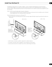
... place with the assistance with at least one other person. 4 ) Use wood screws (not included) to secure the metal fittings to secure your flat panel TV. 1 ) Mark locations for the cord. Follow the steps below to the table. 25 En The wood screws are at the marked locations. 3 ) Lift panel into... To stabilize the flat panel TV on a table or platform, use bare wires for metal fittings and screws on the back edge of the wire is attached. If any part of the table using the panel stand to determine placement. (PRO-151FD) (PRO-111FD) 8 mm to 15 mm (3/8 inch to anchor the metal fittings...
... place with the assistance with at least one other person. 4 ) Use wood screws (not included) to secure the metal fittings to secure your flat panel TV. 1 ) Mark locations for the cord. Follow the steps below to the table. 25 En The wood screws are at the marked locations. 3 ) Lift panel into... To stabilize the flat panel TV on a table or platform, use bare wires for metal fittings and screws on the back edge of the wire is attached. If any part of the table using the panel stand to determine placement. (PRO-151FD) (PRO-111FD) 8 mm to 15 mm (3/8 inch to anchor the metal fittings...

Owner's Manual
Page 27
... power outlet. If the color sensor attached to the rear panel does not operate properly, attach it in a high- Install Your Flat Panel TV 02 Attach the Color Sensor to the Rear Panel Methods of attaching the color sensor to the rear panel differ depending on the rear upper... bank but the procedure is the same for PRO-151FD) 2 ) Loosen the upper two (2) speaker bracket screws. 3 ) Fit the color sensor bracket's lower grooves into the screws. temperature environment, attach the color sensor ...
... power outlet. If the color sensor attached to the rear panel does not operate properly, attach it in a high- Install Your Flat Panel TV 02 Attach the Color Sensor to the Rear Panel Methods of attaching the color sensor to the rear panel differ depending on the rear upper... bank but the procedure is the same for PRO-151FD) 2 ) Loosen the upper two (2) speaker bracket screws. 3 ) Fit the color sensor bracket's lower grooves into the screws. temperature environment, attach the color sensor ...
Owner's Manual
Page 28
The bracket is for PRO-151FD panel but do NOT plug in to stay in place. Adjust the bracket position to the power outlet. Do not use the screws supplied for PRO-111FD. 4 ) Fasten the screws. 5 ) Connect the cable to the color sensor terminal on the sensor window and the panel screen differs ... color sensor to the front panel. When using it to the bottom of the color sensor then replace the bracket. 02 Install Your Flat Panel TV (when side-mounted speakers are not installed) 1 ) Remove the screws of the front panel. Important The color sensor may become hot due to a heat ...
The bracket is for PRO-151FD panel but do NOT plug in to stay in place. Adjust the bracket position to the power outlet. Do not use the screws supplied for PRO-111FD. 4 ) Fasten the screws. 5 ) Connect the cable to the color sensor terminal on the sensor window and the panel screen differs ... color sensor to the front panel. When using it to the bottom of the color sensor then replace the bracket. 02 Install Your Flat Panel TV (when side-mounted speakers are not installed) 1 ) Remove the screws of the front panel. Important The color sensor may become hot due to a heat ...
Owner's Manual
Page 32
...T W W 2.7 Route then Bundle the Power Cord and Cables Once the flat panel TV is mounted and the speaker is designed to bundle cables. The diagram below shows a bundled speaker cable. (PRO-151FD) Speaker cable Cable clamp Bundle cables in a logical pattern that reduces electrical interference from... the power outlet. Unplugging the panel extends the life of the plasma as well as necessary. Lay out the power cord,...
...T W W 2.7 Route then Bundle the Power Cord and Cables Once the flat panel TV is mounted and the speaker is designed to bundle cables. The diagram below shows a bundled speaker cable. (PRO-151FD) Speaker cable Cable clamp Bundle cables in a logical pattern that reduces electrical interference from... the power outlet. Unplugging the panel extends the life of the plasma as well as necessary. Lay out the power cord,...
Owner's Manual
Page 34
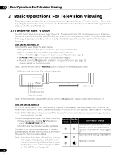
...the side of how the flat panel TV's Power On button (a) is indicators light. Power On Standby 1 ) Press the remote control's TV (a) button or panel's STANDBY/ON button. Monitor the indicators On the front of the viewing area. Sleep indicator (PRO-111FD) Standby indicator Power On indicator Note...: While in lower-left corner (see page 12). Unless the flat panel TV is on the panel's back in Standby, pressing the remote control's TV (a) button causes the flat panel TV to draw some power as...
...the side of how the flat panel TV's Power On button (a) is indicators light. Power On Standby 1 ) Press the remote control's TV (a) button or panel's STANDBY/ON button. Monitor the indicators On the front of the viewing area. Sleep indicator (PRO-111FD) Standby indicator Power On indicator Note...: While in lower-left corner (see page 12). Unless the flat panel TV is on the panel's back in Standby, pressing the remote control's TV (a) button causes the flat panel TV to draw some power as...
Owner's Manual
Page 36
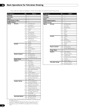
...56 Video Pattern 59 Game Control Pref 45 Room Light Sensor 55 Screen Protection System Setup 43 Label Input 38 Auto Installation 39 Analog TV Setup 41 Digital Tuner Setup 50 Parental Control 72 Closed Captions 121 Digital Audio Output 50 Change Password 37 Language 124 Technical Info ... Mode 43 Sort Favorites * Available when any option other than OPTIMUM is selected from the AV Selection menu. ** Access this option through the Pro Adjust menu when any option other than OPTIMUM is selected from the AV Selection menu. *** Available only when OPTIMUM is selected from the AV ...
...56 Video Pattern 59 Game Control Pref 45 Room Light Sensor 55 Screen Protection System Setup 43 Label Input 38 Auto Installation 39 Analog TV Setup 41 Digital Tuner Setup 50 Parental Control 72 Closed Captions 121 Digital Audio Output 50 Change Password 37 Language 124 Technical Info ... Mode 43 Sort Favorites * Available when any option other than OPTIMUM is selected from the AV Selection menu. ** Access this option through the Pro Adjust menu when any option other than OPTIMUM is selected from the AV Selection menu. *** Available only when OPTIMUM is selected from the AV ...
Owner's Manual
Page 46
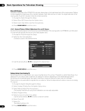
...broadcast signal level. Only analog channels set the indicator, follow the directions below. 1 ) Access the Option through the Setup. 2 ) Select Analog TV Setup from the System Setup menu. 3 ) Select Manual Adjust from an antenna. To set using Auto Installation are manually adjustable. 4 ) Select ...Program Entry. 5 ) Select a channel number to the desired level. AV Selection Contrast Brightness Color Tint Sharpness Pro Adjust Reset Picture : PERFORMANCE : 40 : 0 : 0 : 0 : 0 3 ) Use the arrow buttons (/) to adjust to be adjusted. Your ...
...broadcast signal level. Only analog channels set the indicator, follow the directions below. 1 ) Access the Option through the Setup. 2 ) Select Analog TV Setup from the System Setup menu. 3 ) Select Manual Adjust from an antenna. To set using Auto Installation are manually adjustable. 4 ) Select ...Program Entry. 5 ) Select a channel number to the desired level. AV Selection Contrast Brightness Color Tint Sharpness Pro Adjust Reset Picture : PERFORMANCE : 40 : 0 : 0 : 0 : 0 3 ) Use the arrow buttons (/) to adjust to be adjusted. Your ...


