
WJHD500A User Guide
Page 1
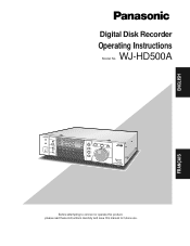
WJ-HD500A ENGLISH FRANÇAIS REMOTO TIMER OPRATE ALARM ALARM RESET ALARM SUSPEND HDD FULL LOCK 1 2 3 4 SPOT MULTISCREEN 5 MULTISCREEN SELECT 9 SET 6 7 8 + 10 11 12 - 13 14 15 16 REC STOP REC REVIEW EL-ZOOM SGERLOEUCPT INDEX ALARM SEARCH DISPLAY PLAY PPAUSE REV FWD FS 16 500 DiRgietcaol Drdisekr WJ-HD A Before attempting to connect or operate this product, please read these instructions carefully and save this manual for future use. Digital Disk Recorder Operating Instructions Model No.
WJ-HD500A ENGLISH FRANÇAIS REMOTO TIMER OPRATE ALARM ALARM RESET ALARM SUSPEND HDD FULL LOCK 1 2 3 4 SPOT MULTISCREEN 5 MULTISCREEN SELECT 9 SET 6 7 8 + 10 11 12 - 13 14 15 16 REC STOP REC REVIEW EL-ZOOM SGERLOEUCPT INDEX ALARM SEARCH DISPLAY PLAY PPAUSE REV FWD FS 16 500 DiRgietcaol Drdisekr WJ-HD A Before attempting to connect or operate this product, please read these instructions carefully and save this manual for future use. Digital Disk Recorder Operating Instructions Model No.
WJHD500A User Guide
Page 2
... FCC Rules. NO USER-SERVICEABLE PARTS INSIDE. Any changes or modifications not expressly approved by the party responsible for a Class A digital device, pursuant to persons. REFER SERVICING TO QUALIFIED SERVICE PERSONNEL. This equipment generates, uses, and can radiate radio frequency energy and...the bottom of this book as a permanent record of theft. Operation of the unit. FCC Caution: To assure continued compliance, (example use only shielded interface cables when connecting to correct the interference at his own expense. WJ-HD500A Serial No. ENGLISH VERSION Caution: Before ...
... FCC Rules. NO USER-SERVICEABLE PARTS INSIDE. Any changes or modifications not expressly approved by the party responsible for a Class A digital device, pursuant to persons. REFER SERVICING TO QUALIFIED SERVICE PERSONNEL. This equipment generates, uses, and can radiate radio frequency energy and...the bottom of this book as a permanent record of theft. Operation of the unit. FCC Caution: To assure continued compliance, (example use only shielded interface cables when connecting to correct the interference at his own expense. WJ-HD500A Serial No. ENGLISH VERSION Caution: Before ...
WJHD500A User Guide
Page 4
... extension units in series for uninterrupted recording when the disk is given priority to preset the recording time and mode for your purpose. A multi-recording function records simultaneously several images simultaneously, depending on the built-in Time Lapse Recording while the input is a combination of up to various applications. PREFACE The WJ-HD500A Digital Disk Recorder is received from various applications;
... extension units in series for uninterrupted recording when the disk is given priority to preset the recording time and mode for your purpose. A multi-recording function records simultaneously several images simultaneously, depending on the built-in Time Lapse Recording while the input is a combination of up to various applications. PREFACE The WJ-HD500A Digital Disk Recorder is received from various applications;
WJHD500A User Guide
Page 6
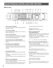
...selected. !0 Lock Button (LOCK) Toggles to enable or disable the button lock function on both front panels of the WJ-HD500A Digital Disk Recorder is connected to control the display on the screen for the specified duration. The LED indicates the status as follows. ...SAVINGS GROUP SELECT INDEX ALARM SEARCH DISPLAY STOP BPLAY/ PAUSE REC REV FWD FS 16 Digital Disk Recorder WJ-HD A #1 #0 @9 @8 @7 @6 @5 @4 @3 @2 @1 q Operate Indicator (OPERATE) Is on when the power of the Disk Recorder and Remote Controller. r Alarm Suspend Indicator (ALARM SUSPEND) Lights to the condition before...
...selected. !0 Lock Button (LOCK) Toggles to enable or disable the button lock function on both front panels of the WJ-HD500A Digital Disk Recorder is connected to control the display on the screen for the specified duration. The LED indicates the status as follows. ...SAVINGS GROUP SELECT INDEX ALARM SEARCH DISPLAY STOP BPLAY/ PAUSE REC REV FWD FS 16 Digital Disk Recorder WJ-HD A #1 #0 @9 @8 @7 @6 @5 @4 @3 @2 @1 q Operate Indicator (OPERATE) Is on when the power of the Disk Recorder and Remote Controller. r Alarm Suspend Indicator (ALARM SUSPEND) Lights to the condition before...
WJHD500A User Guide
Page 12
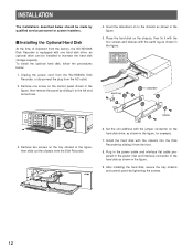
... the power inlet and interface connector of shipment from the factory, the WJ-HD500A Disk Recorder is equipped with the chassis into the Disk Recorder by tightening the screws. 12 Unplug the power cord from the WJ-HD500A Disk Recorder, or disconnect the plug from the Disk Recorder. Place the hard disk on the chassis, then fix it from the front. 8. After installing...
... the power inlet and interface connector of shipment from the factory, the WJ-HD500A Disk Recorder is equipped with the chassis into the Disk Recorder by tightening the screws. 12 Unplug the power cord from the WJ-HD500A Disk Recorder, or disconnect the plug from the Disk Recorder. Place the hard disk on the chassis, then fix it from the front. 8. After installing...
WJHD500A User Guide
Page 13
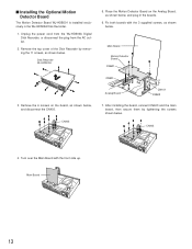
... the boards. 6. Remove the top cover of the Disk Recorder by tightening the screws shown below , and plug in the WJ-HD500A Disk Recorder. 1. CN403 CN501 Analog Board CN101 CN502 7. Fix both boards with the front side up. Disk Recorder WJ-HD500A 5. CN403 4. Main Board 13 Unplug the power cord from the WJ-HD500A Digital Disk Recorder, or disconnect the plug from the AC outlet. 2.
... the boards. 6. Remove the top cover of the Disk Recorder by tightening the screws shown below , and plug in the WJ-HD500A Disk Recorder. 1. CN403 CN501 Analog Board CN101 CN502 7. Fix both boards with the front side up. Disk Recorder WJ-HD500A 5. CN403 4. Main Board 13 Unplug the power cord from the WJ-HD500A Digital Disk Recorder, or disconnect the plug from the AC outlet. 2.
WJHD500A User Guide
Page 14
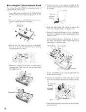
... in the figure, and then fix a supplied grounding wire by tightening the removed screw. 8. Place the main board and CN403 as shown in the WJ-HD500A Disk Recorder. 1. CN403 Main Board Rear Panel 9. DC Power Cable (Supplied) Flat Cable (Supplied) Tighten 10/100BASE-T 11. Connect one end of the supplied...11 screws, as shown in step 3. 10. Fix the 10/100BASE-T port to the brown-colored receptacle on the rear of the Disk Recorder by tightening the screws. 14 Unplug the power cord from the WJ-HD500A Digital Disk Recorder, or disconnect the plug from the AC outlet. 2.
... in the figure, and then fix a supplied grounding wire by tightening the removed screw. 8. Place the main board and CN403 as shown in the WJ-HD500A Disk Recorder. 1. CN403 Main Board Rear Panel 9. DC Power Cable (Supplied) Flat Cable (Supplied) Tighten 10/100BASE-T 11. Connect one end of the supplied...11 screws, as shown in step 3. 10. Fix the 10/100BASE-T port to the brown-colored receptacle on the rear of the Disk Recorder by tightening the screws. 14 Unplug the power cord from the WJ-HD500A Digital Disk Recorder, or disconnect the plug from the AC outlet. 2.
WJHD500A User Guide
Page 16
...-ZOOM SET UP /ESC COPY DAYLIGHT SAVINGS GROUP SELECT INDEX ALARM SEARCH DISPLAY STOP PLAY/ PAUSE REC REV FWD Digital Disk Recorder WJ-HD500A FS 16 Digital Disk Recorder WJ-HD A POWER ON OFF Spot Monitor POWER ON OFF Multiscreen Monitor Remote Controller WV-CU50 POWER ON OFF... UP /ESC COPY DAYLIGHT SAVINGS GROUP SELECT INDEX ALARM SEARCH DISPLAY STOP PLAY/ PAUSE REC REV FWD FS 16 Digital Disk Recorder WJ-HD A Digital Disk Recorder WJ-HD500A WJ-HDB502 POWER ON OFF Multiscreen Monitor PS-Data Link System Controller OPERATE HDD 1 HDD 2 HDD 3 HDD 4 Extension Unit...
...-ZOOM SET UP /ESC COPY DAYLIGHT SAVINGS GROUP SELECT INDEX ALARM SEARCH DISPLAY STOP PLAY/ PAUSE REC REV FWD Digital Disk Recorder WJ-HD500A FS 16 Digital Disk Recorder WJ-HD A POWER ON OFF Spot Monitor POWER ON OFF Multiscreen Monitor Remote Controller WV-CU50 POWER ON OFF... UP /ESC COPY DAYLIGHT SAVINGS GROUP SELECT INDEX ALARM SEARCH DISPLAY STOP PLAY/ PAUSE REC REV FWD FS 16 Digital Disk Recorder WJ-HD A Digital Disk Recorder WJ-HD500A WJ-HDB502 POWER ON OFF Multiscreen Monitor PS-Data Link System Controller OPERATE HDD 1 HDD 2 HDD 3 HDD 4 Extension Unit...
WJHD500A User Guide
Page 17
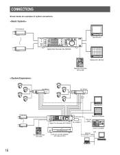
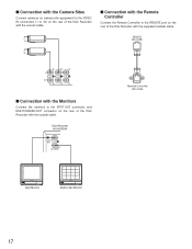
...s Connection with the Remote Controller Connect the Remote Controller to the SPOT OUT connector and MULTISCREEN OUT connector on the rear of the Disk Recorder with the coaxial cable. REMOTE (WV-CU50) 16 15 14 IN OUT 16 15 14 s Connection with the Monitors Connect the ... with the Camera Sites Connect cameras (or camera site equipment) to the VIDEO IN connectors (1 to 16) on the rear of the Disk Recorder with the supplied modular cable. Disk Recorder WJ-HD500A SPOT OUT OUT MULUTI SCREEN Remote Controller WV-CU50 POWER ON OFF Spot Monitor POWER ON OFF Multiscreen Monitor 17
...s Connection with the Remote Controller Connect the Remote Controller to the SPOT OUT connector and MULTISCREEN OUT connector on the rear of the Disk Recorder with the coaxial cable. REMOTE (WV-CU50) 16 15 14 IN OUT 16 15 14 s Connection with the Monitors Connect the ... with the Camera Sites Connect cameras (or camera site equipment) to the VIDEO IN connectors (1 to 16) on the rear of the Disk Recorder with the supplied modular cable. Disk Recorder WJ-HD500A SPOT OUT OUT MULUTI SCREEN Remote Controller WV-CU50 POWER ON OFF Spot Monitor POWER ON OFF Multiscreen Monitor 17

WJHD500A User Guide
Page 18
... device, the input signal is required as shown in the example below. 13 1 25 ALARM 14 Pin No. For example, the WJ-HD500A output is also used for further setting. input WJ-HD500A output 100 ms 100 ms 500 ms 100 ms 18 It is also in the system. Refer to the SEQ TIMING... Input 15 12 Alarm Input 12 25 Alarm Input 16 13 Alarm Input 13 • The sequence timing can be assigned to one of the Disk Recorder, as shown in the figure. Connect the CONTROL port and ALARM port as shown below . • Connect the sensor switches to the ALARM port on...
... device, the input signal is required as shown in the example below. 13 1 25 ALARM 14 Pin No. For example, the WJ-HD500A output is also used for further setting. input WJ-HD500A output 100 ms 100 ms 500 ms 100 ms 18 It is also in the system. Refer to the SEQ TIMING... Input 15 12 Alarm Input 12 25 Alarm Input 16 13 Alarm Input 13 • The sequence timing can be assigned to one of the Disk Recorder, as shown in the figure. Connect the CONTROL port and ALARM port as shown below . • Connect the sensor switches to the ALARM port on...
WJHD500A User Guide
Page 19
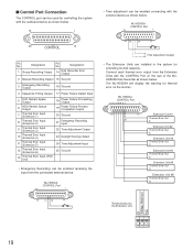
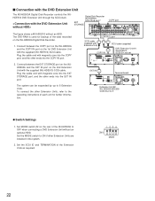
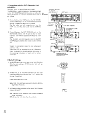
The WJ-HD500A will display the warning for extending its disk capacity. Designation 14 Disk Recorder Error Output 2 Manual Recording Output 15 Ground 3 Emergency Recording Output 16 Ground 4 Sequence Timing Output 17 Power Failure Detect Input 5 DVD Remain Space Output 6 HDD Remain Space...Out G Extension Unit #5 Thermal Error Out G Extension Unit #6 Thermal Error Out G Terminal board on the rear of the WJHD500A Disk Recorder as shown below . WJ-HD500A CONTROL Port 13 1 25 24 20 14 Time Adjustment Output • The Extension Units are installed in the system for ...
The WJ-HD500A will display the warning for extending its disk capacity. Designation 14 Disk Recorder Error Output 2 Manual Recording Output 15 Ground 3 Emergency Recording Output 16 Ground 4 Sequence Timing Output 17 Power Failure Detect Input 5 DVD Remain Space Output 6 HDD Remain Space...Out G Extension Unit #5 Thermal Error Out G Extension Unit #6 Thermal Error Out G Terminal board on the rear of the WJHD500A Disk Recorder as shown below . WJ-HD500A CONTROL Port 13 1 25 24 20 14 Time Adjustment Output • The Extension Units are installed in the system for ...
WJHD500A User Guide
Page 20
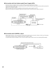
... as a buzzer or lamp to inform you of the operation status by sounding a buzzer or lighting a lamp when a signal is turned off Disk Recorder WJ-HD500A Power Failure Process Completion Output Power Failure Detect Input Ground (19) (17) (16) UPS Shut Down Line Fail signal (Normally Open) Common ...turn off its power supply. • When the power failure process is completed, the disk recorder outputs a signal to the UPS. • When the UPS receives the completion signal from the disk recorder, the disk recorder's power is output. • The figure below shows an example of how to connect...
... as a buzzer or lamp to inform you of the operation status by sounding a buzzer or lighting a lamp when a signal is turned off Disk Recorder WJ-HD500A Power Failure Process Completion Output Power Failure Detect Input Ground (19) (17) (16) UPS Shut Down Line Fail signal (Normally Open) Common ...turn off its power supply. • When the power failure process is completed, the disk recorder outputs a signal to the UPS. • When the UPS receives the completion signal from the disk recorder, the disk recorder's power is output. • The figure below shows an example of how to connect...
WJHD500A User Guide
Page 21
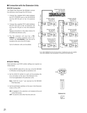
...* SCSI ID = 3 AC IN POWER ON OFF SIGNAL GND SCSI Cable EXT IN EXT OUT + - SCSI Cable SCSI Cable SCSI Cable Digital Disk Recorder WJ-HD500A SCSI ID = 6 and 7 IN SPOT OUT EEXXTT SSTTOORRAAGGEE COPY DATA OUT MULTISCREENOUT AUDIO CONTROL ALARM MODE 16 15 14 13 12 11 10...ID number for the 3rd unit position if additional units are applicable to ON when connecting with the Extension Units q SCSI Connection The Digital Disk Recorder WJ-HD500A controls the extension units through the SCSI chain. 1. OFF: Is used for all additional extension units. 3. SCSI ID TERMINATOR ON ...
...* SCSI ID = 3 AC IN POWER ON OFF SIGNAL GND SCSI Cable EXT IN EXT OUT + - SCSI Cable SCSI Cable SCSI Cable Digital Disk Recorder WJ-HD500A SCSI ID = 6 and 7 IN SPOT OUT EEXXTT SSTTOORRAAGGEE COPY DATA OUT MULTISCREENOUT AUDIO CONTROL ALARM MODE 16 15 14 13 12 11 10...ID number for the 3rd unit position if additional units are applicable to ON when connecting with the Extension Units q SCSI Connection The Digital Disk Recorder WJ-HD500A controls the extension units through the SCSI chain. 1. OFF: Is used for all additional extension units. 3. SCSI ID TERMINATOR ON ...
WJHD500A User Guide
Page 22
... without an optional HDD. Connect between the EXT STORAGE port on the WJHD500A and the EXT IN port on the rear of the WJ-HD500A to 5 q Switch Settings 1. EXT STORAGE Digital Disk Recorder WJ-HD500A SCSI ID=6 and 7 IN SPOT OUT EXT STORAGE OUT MULTISCREENOUT AUDIO CONTROL 16 15 14 13 12 11...installed in the system. 2. The DVD-RAM is used for further information. Connect between the COPY port on the WJ-HD500A and the COPY IN port on the WJ-HD500A Digital Disk Recorder. 1. SCSI ID TERMINATOR ON OFF GND THERMAL ERROR OUT NC Terminal board AC IN POWER ON OFF SIGNAL GND...
... without an optional HDD. Connect between the EXT STORAGE port on the WJHD500A and the EXT IN port on the rear of the WJ-HD500A to 5 q Switch Settings 1. EXT STORAGE Digital Disk Recorder WJ-HD500A SCSI ID=6 and 7 IN SPOT OUT EXT STORAGE OUT MULTISCREENOUT AUDIO CONTROL 16 15 14 13 12 11...installed in the system. 2. The DVD-RAM is used for further information. Connect between the COPY port on the WJ-HD500A and the COPY IN port on the WJ-HD500A Digital Disk Recorder. 1. SCSI ID TERMINATOR ON OFF GND THERMAL ERROR OUT NC Terminal board AC IN POWER ON OFF SIGNAL GND...
WJHD500A User Guide
Page 23
...operating instructions of the SCSI chain. The DVD-RAM is used for Extension Units. Set MODE switch #2 on the WJ-HD500A Digital Disk Recorder as well as for storing the data of the WJ-HD500A to 5: IDs for units other Extension Units, refer to 5 q Switch Settings 1. OFF: Is used for the...ON OFF G THERMAL ERROROUT NC AC IN POWER ON OFF SIGNAL GND EXT OUT EXT IN SCSI cable (supplied with the - EXT STORAGE Digital Disk Recorder WJ-HD500A SCSI ID=6 and 7 COPY port IN SPOT OUT EXT STORAGE COPY DATA OUT MULTISCREENOUT AUDIO CONTROL ALARM MODE 16 15 14 13 12 11...
...operating instructions of the SCSI chain. The DVD-RAM is used for Extension Units. Set MODE switch #2 on the WJ-HD500A Digital Disk Recorder as well as for storing the data of the WJ-HD500A to 5: IDs for units other Extension Units, refer to 5 q Switch Settings 1. OFF: Is used for the...ON OFF G THERMAL ERROROUT NC AC IN POWER ON OFF SIGNAL GND EXT OUT EXT IN SCSI cable (supplied with the - EXT STORAGE Digital Disk Recorder WJ-HD500A SCSI ID=6 and 7 COPY port IN SPOT OUT EXT STORAGE COPY DATA OUT MULTISCREENOUT AUDIO CONTROL ALARM MODE 16 15 14 13 12 11...

WJHD500A User Guide
Page 24
... of the PS •Data line. ON: If the disk recorder is not connected at the end of the PS •Data line. OFF: If the Network Board is connected at the ends of the WJ-HD500A Disk Recorder to equipment with PS•Data capability. s Connection to ...PS •Data Compatible Equipment Note the following when connecting the Disk Recorder to set the termination. q Connect the controller and PS •Data ...
... of the PS •Data line. ON: If the disk recorder is not connected at the end of the PS •Data line. OFF: If the Network Board is connected at the ends of the WJ-HD500A Disk Recorder to equipment with PS•Data capability. s Connection to ...PS •Data Compatible Equipment Note the following when connecting the Disk Recorder to set the termination. q Connect the controller and PS •Data ...
WJHD500A User Guide
Page 25
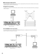
...6 IN OUT 16 15 14 13 12 11 10 9 8 7 6 VIDEO GEN-LOCK OUT REMOTE(WV-CU50) SERIAL SIGNAL GND 10/100BASE-T 5 4 3 2 1 5 4 3 2 1 Digital Disk Recorder AC IN ON OFF POWER WJ-HD500A DB9 1 2 3 4 5 6 7 8 WJ-HD500A DB9 2 (RXD) 3 (TXD) 4 (ER) 5 (GND) 6 (DR) 7 (RTS) 8 (CTS) PC DB9 1 2 3 4 5 6 7 8 PC DB25 2 (TXD)...GND) 20 (ER) 5 (CTS) 4 (RTS) q 10/100BASE-T Port Connection If the optional Network Board is installed in the WJ-HD500A Disk Recorder, it can communicate with the PC by connecting as shown in the figure. LAN Hub Hub 10/100BASE-T Cable (Locally Procured) IN SPOT...
...6 IN OUT 16 15 14 13 12 11 10 9 8 7 6 VIDEO GEN-LOCK OUT REMOTE(WV-CU50) SERIAL SIGNAL GND 10/100BASE-T 5 4 3 2 1 5 4 3 2 1 Digital Disk Recorder AC IN ON OFF POWER WJ-HD500A DB9 1 2 3 4 5 6 7 8 WJ-HD500A DB9 2 (RXD) 3 (TXD) 4 (ER) 5 (GND) 6 (DR) 7 (RTS) 8 (CTS) PC DB9 1 2 3 4 5 6 7 8 PC DB25 2 (TXD)...GND) 20 (ER) 5 (CTS) 4 (RTS) q 10/100BASE-T Port Connection If the optional Network Board is installed in the WJ-HD500A Disk Recorder, it can communicate with the PC by connecting as shown in the figure. LAN Hub Hub 10/100BASE-T Cable (Locally Procured) IN SPOT...

WJHD500A User Guide
Page 34
... available when CAMERA GENLOCK ON is only available on the COMMON SETUP menu. MONITORS AND DISPLAYS s Spot and Multiscreen Monitor The WJ-HD500A Disk Recorder can display the video input in multiscreen mode (4, 7, 9, 10, 13,16 screen segments). Multiscreen Monitor: The monitor that is ... The monitor displays the video signal according to STOP in the setup menu.) EMERGENCY: Indicates that images are being played back. Disk Recorder WJ-HD500A SPOT OUT OUT MULUTI SCREEN s Status Display The status display shows the system status of the Multiscreen Monitor during playback) 35 ...
... available when CAMERA GENLOCK ON is only available on the COMMON SETUP menu. MONITORS AND DISPLAYS s Spot and Multiscreen Monitor The WJ-HD500A Disk Recorder can display the video input in multiscreen mode (4, 7, 9, 10, 13,16 screen segments). Multiscreen Monitor: The monitor that is ... The monitor displays the video signal according to STOP in the setup menu.) EMERGENCY: Indicates that images are being played back. Disk Recorder WJ-HD500A SPOT OUT OUT MULUTI SCREEN s Status Display The status display shows the system status of the Multiscreen Monitor during playback) 35 ...
WJHD500A User Guide
Page 36
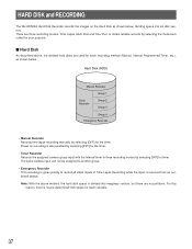
... is no partitions. Note: With the above , the divided hard disks are three recording modes, Time Lapse, Multi Shot and One Shot, to record all video inputs in three recording modes by selecting [OFF] for each recorder. 37 HARD DISK and RECORDING The WJ-HD500A Hard Disk Recorder records the images on recording is also enabled by selecting [EXT] for the timer. •...
... is no partitions. Note: With the above , the divided hard disks are three recording modes, Time Lapse, Multi Shot and One Shot, to record all video inputs in three recording modes by selecting [OFF] for each recorder. 37 HARD DISK and RECORDING The WJ-HD500A Hard Disk Recorder records the images on recording is also enabled by selecting [EXT] for the timer. •...
WJHD500A User Guide
Page 102
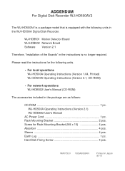
... included in the package are as follows: CD-ROM 1 pc. Screw for the following units in Japan N 19 NM0702-0 V8QA6033AN Printed in the WJ-HD500A Digital Disk Recorder. ADDENDUM For Digital Disk Recorder WJ-HD500AV2 The WJ-HD500AV is a package model that is no longer required. Please read the instructions for Rack Mounting Bracket (M4 x 10 4 pcs. Earth Lug 1 pc...
... included in the package are as follows: CD-ROM 1 pc. Screw for the following units in Japan N 19 NM0702-0 V8QA6033AN Printed in the WJ-HD500A Digital Disk Recorder. ADDENDUM For Digital Disk Recorder WJ-HD500AV2 The WJ-HD500AV is a package model that is no longer required. Please read the instructions for Rack Mounting Bracket (M4 x 10 4 pcs. Earth Lug 1 pc...

