Operating Instructions
Page 4
... 45 Network status page 45 Using the PJLinkTM protocol 46 Supported commands 46 PJLinkTM security authentication 46 Setting the security 47 PASSWORD 47 PASSWORD CHANGE 47 DISPLAY SETTING 47 TEXT CHANGE 47 CONTROL DEVICE SETUP 47 Using the serial terminals 48 Examples of connection 48 Pin assignments and signal names 48 Communication conditions 48 Basic format 48 Control commands 49 Cable specifications 49 Using the Remote 2 terminal 49 Indication of lamp monitor 50 Cleaning and replacement of air filter 51...
... 45 Network status page 45 Using the PJLinkTM protocol 46 Supported commands 46 PJLinkTM security authentication 46 Setting the security 47 PASSWORD 47 PASSWORD CHANGE 47 DISPLAY SETTING 47 TEXT CHANGE 47 CONTROL DEVICE SETUP 47 Using the serial terminals 48 Examples of connection 48 Pin assignments and signal names 48 Communication conditions 48 Basic format 48 Control commands 49 Cable specifications 49 Using the Remote 2 terminal 49 Indication of lamp monitor 50 Cleaning and replacement of air filter 51...

Operating Instructions
Page 5
... the projector is dropped or the cabinet is used . • Strong light is not inserted correctly, electric shocks or overheating could result. • Check that might be dangerous. Do not look into water or let it may occur. • Use the dedicated ceiling mount bracket specified for an extended period of time, pull the power cord plug out from becoming covered in...
... the projector is dropped or the cabinet is used . • Strong light is not inserted correctly, electric shocks or overheating could result. • Check that might be dangerous. Do not look into water or let it may occur. • Use the dedicated ceiling mount bracket specified for an extended period of time, pull the power cord plug out from becoming covered in...
Operating Instructions
Page 7
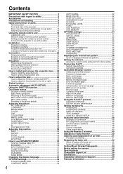
... replacement of the lamp unit and check the inside the projector at least once a year. • If dust is a good idea to clean the inside the projector without being cleaned out, it can result if this may cause the user to observe this is not done. If not using the projector for remote [N2QAYB000164 x 1] [K2CG3FZ00008 x 1] control unit (AA) [R6DW/2ST] Lens cover [TKKL5244-1 x 1] Wire cable...
... replacement of the lamp unit and check the inside the projector at least once a year. • If dust is a good idea to clean the inside the projector without being cleaned out, it can result if this may cause the user to observe this is not done. If not using the projector for remote [N2QAYB000164 x 1] [K2CG3FZ00008 x 1] control unit (AA) [R6DW/2ST] Lens cover [TKKL5244-1 x 1] Wire cable...
Operating Instructions
Page 8
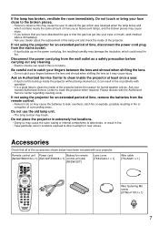
... just after switching on the screen. If a chemical wipe is installed in a place free from the receptacle before adjusting the lens focus. The product may increase, which they are susceptible to used continuously for installation. Do not clean the lens surface with the supplied lens cap when the projector is used for low ceiling: Model No. Install the product in the vicinity of at the time of use a cloth dampened...
... just after switching on the screen. If a chemical wipe is installed in a place free from the receptacle before adjusting the lens focus. The product may increase, which they are susceptible to used continuously for installation. Do not clean the lens surface with the supplied lens cap when the projector is used for low ceiling: Model No. Install the product in the vicinity of at the time of use a cloth dampened...
Operating Instructions
Page 9
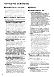
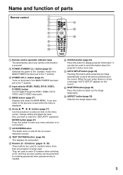
...) Switches the image aspect ratio. 9 ENTER button (page 27) Press this button while projecting an image automatically corrects the picture positioning on -screen indication function. Name and function of parts Remote control Remote control operation indicator lamp The lamp flashes when any remote control button is active, a message "AUTO SETUP" appears on the power if the MAIN POWER has been put to toggle through the RGB1, RGB2, DVI-D, VIDEO and S-VIDEO input ports. STATUS button (page 25) Press this button to display projector information. MENU button (page 27) Displays...
...) Switches the image aspect ratio. 9 ENTER button (page 27) Press this button while projecting an image automatically corrects the picture positioning on -screen indication function. Name and function of parts Remote control Remote control operation indicator lamp The lamp flashes when any remote control button is active, a message "AUTO SETUP" appears on the power if the MAIN POWER has been put to toggle through the RGB1, RGB2, DVI-D, VIDEO and S-VIDEO input ports. STATUS button (page 25) Press this button to display projector information. MENU button (page 27) Displays...
Operating Instructions
Page 11
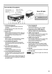
... cover (white top panel). 11 Lens left/right adjusting dial (page 25) Turn this receptacle. Front and side of the projector Side-mounted connection terminals (page 13) Status LED lights (Refer to the figure on the right.) Status LED lights AC IN terminal (page 22) Connect the supplied line power cord into this clockwise to move it to green when the POWER ON button of the remote control or the main unit is pressed. Air filter...
... cover (white top panel). 11 Lens left/right adjusting dial (page 25) Turn this receptacle. Front and side of the projector Side-mounted connection terminals (page 13) Status LED lights (Refer to the figure on the right.) Status LED lights AC IN terminal (page 22) Connect the supplied line power cord into this clockwise to move it to green when the POWER ON button of the remote control or the main unit is pressed. Air filter...
Operating Instructions
Page 12
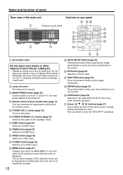
... the remote control. RGB2 button (page 22) Switches to S-VIDEO input. It can be displayed by holding down the menu key for lens focus, zoom and shift (position). ENTER button (page 27) Press this button while projecting an image automatically corrects the picture positioning on the screen. POWER ON ( I " and off "O" the main power applied to the projector. S-VIDEO button (page 22) Switches to RGB2 input. DVI button (page 22) Switches to video input. MAIN POWER switch (page 22) Use this port...
... the remote control. RGB2 button (page 22) Switches to S-VIDEO input. It can be displayed by holding down the menu key for lens focus, zoom and shift (position). ENTER button (page 27) Press this button while projecting an image automatically corrects the picture positioning on the screen. POWER ON ( I " and off "O" the main power applied to the projector. S-VIDEO button (page 22) Switches to RGB2 input. DVI button (page 22) Switches to video input. MAIN POWER switch (page 22) Use this port...
Operating Instructions
Page 22
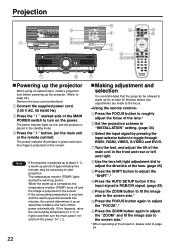
... and then turn the main power "on" and turn on the screen. Projection R/PR G/Y B/PB SYNC/HD VD VIDEO IN S-VIDEO IN REMOTE 1 IN OUT RGB 1 IN REMOTE 2 IN IN SE Powering up the projector When using an optional lens, install a projection lens before any adjustments are made to the focus. Connect the supplied power cord. (120 V AC, 50 Hz/60 Hz) Press the " I " button. [on the main unit or the remote control] The power indicator illuminates in...
... and then turn the main power "on" and turn on the screen. Projection R/PR G/Y B/PB SYNC/HD VD VIDEO IN S-VIDEO IN REMOTE 1 IN OUT RGB 1 IN REMOTE 2 IN IN SE Powering up the projector When using an optional lens, install a projection lens before any adjustments are made to the focus. Connect the supplied power cord. (120 V AC, 50 Hz/60 Hz) Press the " I " button. [on the main unit or the remote control] The power indicator illuminates in...

Operating Instructions
Page 25
... the maximum adjustment position to supply images with a bright white frame at the outermost periphery containing characters etc. With Composite sync and G-SYNC sync signals and some types of the projection screen width. In this case, manually adjust the "CLOCK PHASE". • Automatic adjustments cannot be used to be performed when images with undue force may be used to hide the images temporarily. AROUND LAMP MAIN VERSION NETWORK VERSION...
... the maximum adjustment position to supply images with a bright white frame at the outermost periphery containing characters etc. With Composite sync and G-SYNC sync signals and some types of the projection screen width. In this case, manually adjust the "CLOCK PHASE". • Automatic adjustments cannot be used to be performed when images with undue force may be used to hide the images temporarily. AROUND LAMP MAIN VERSION NETWORK VERSION...
Operating Instructions
Page 26
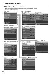
... INSTALLATION ALTITUDE DIRECTION LAMP SELECT LAMP RELAY RS-232C SYSTEM INFORMATION AUTO POWER OFF DATE AND TIME PASSWORD ALL FRONT-FLOOR LOW HORIZONTAL DUAL OFF DISABLE MENU SELECT CHANGE MENU SELECT CHANGE For S-Video/Video/YPBPR signals PICTURE PICTURE MODE CONTRAST BRIGHTNESS COLOR TINT COLOR TEMP WHITE GAIN SYSTEM DAYLIGHT VIEW SHARPNESS NOISE REDUCTION AI SYSTEM SELECTOR STANDARD 0 0 0 0 DEFAULT +6 OFF +6 1 ON AUTO MENU SELECT CHANGE ADVANCED MENU (page 30) ADVANCED MENU DIGITAL CINEMA REALITY BLANKING INPUT RESOLUTION CLAMP POSITION RASTER POSITION XGA MODE...
... INSTALLATION ALTITUDE DIRECTION LAMP SELECT LAMP RELAY RS-232C SYSTEM INFORMATION AUTO POWER OFF DATE AND TIME PASSWORD ALL FRONT-FLOOR LOW HORIZONTAL DUAL OFF DISABLE MENU SELECT CHANGE MENU SELECT CHANGE For S-Video/Video/YPBPR signals PICTURE PICTURE MODE CONTRAST BRIGHTNESS COLOR TINT COLOR TEMP WHITE GAIN SYSTEM DAYLIGHT VIEW SHARPNESS NOISE REDUCTION AI SYSTEM SELECTOR STANDARD 0 0 0 0 DEFAULT +6 OFF +6 1 ON AUTO MENU SELECT CHANGE ADVANCED MENU (page 30) ADVANCED MENU DIGITAL CINEMA REALITY BLANKING INPUT RESOLUTION CLAMP POSITION RASTER POSITION XGA MODE...
Operating Instructions
Page 29
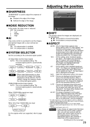
... standard signals are input*2, the images are displayed with the "AUTO" setting, change the setting to the aspect ratio of the original picture. (Continued on all the panel pixels in the horizontal direction. Adjusting the position POSITION SHIFT ASPECT ZOOM CLOCK PHASE KEYSTONE 4:3 +16 MENU SELECT SUB MENU SHIFT The position where the images are displayed with their inherent aspect ratio intact. When wide-screen signals are input*3, the images are displayed...
... standard signals are input*2, the images are displayed with the "AUTO" setting, change the setting to the aspect ratio of the original picture. (Continued on all the panel pixels in the horizontal direction. Adjusting the position POSITION SHIFT ASPECT ZOOM CLOCK PHASE KEYSTONE 4:3 +16 MENU SELECT SUB MENU SHIFT The position where the images are displayed with their inherent aspect ratio intact. When wide-screen signals are input*3, the images are displayed...

Operating Instructions
Page 30
... along either horizontal bound of the picture. For upper adjustment For lower adjustment For left adjustment For right adjustment How to use ADVANCED MENU ADVANCED MENU DIGITAL CINEMA REALITY BLANKING INPUT RESOLUTION CLAMP POSITION RASTER POSITION XGA MODE SXGA MODE AUTO 1 XGA SXGA MENU SELECT CHANGE DIGITAL CINEMA REALITY Increase the vertical resolution when the S-Video/ Video signal input or 480i, 576i, 1080/60i or 1080/50i signal input is not adjustable if no correction was made...
... along either horizontal bound of the picture. For upper adjustment For lower adjustment For left adjustment For right adjustment How to use ADVANCED MENU ADVANCED MENU DIGITAL CINEMA REALITY BLANKING INPUT RESOLUTION CLAMP POSITION RASTER POSITION XGA MODE SXGA MODE AUTO 1 XGA SXGA MENU SELECT CHANGE DIGITAL CINEMA REALITY Increase the vertical resolution when the S-Video/ Video signal input or 480i, 576i, 1080/60i or 1080/50i signal input is not adjustable if no correction was made...

Operating Instructions
Page 32
.... BLUE : Set screen color to use for "LOGO1". LOGO1 : The picture registered by the user will be adjusted and registered for each time signals are input when signals are two modes for the same kind of image adjustment data (PICTURE, POSITION, ADVANCED MENU adjustment values) for adjusting to make the detailed settings. STARTUP LOGO This sets the startup logo that is projected when the power is used at a conference. AUTO SIGNAL The position where the screen is displayed can...
.... BLUE : Set screen color to use for "LOGO1". LOGO1 : The picture registered by the user will be adjusted and registered for each time signals are input when signals are two modes for the same kind of image adjustment data (PICTURE, POSITION, ADVANCED MENU adjustment values) for adjusting to make the detailed settings. STARTUP LOGO This sets the startup logo that is projected when the power is used at a conference. AUTO SIGNAL The position where the screen is displayed can...

Operating Instructions
Page 33
... not provide images or otherwise operate properly. DVI EDID When the projector and external equipment are connected by DVI connection but a proper image cannot be obtained, switch this setting. EDID1 Select this mainly when external equipment (DVD player, etc.) that outputs still image video signals is set the function for the remote control's FUNC1 button. FUNC1 The user can specify the position of the on-screen menu indications. 1 (Top...
... not provide images or otherwise operate properly. DVI EDID When the projector and external equipment are connected by DVI connection but a proper image cannot be obtained, switch this setting. EDID1 Select this mainly when external equipment (DVD player, etc.) that outputs still image video signals is set the function for the remote control's FUNC1 button. FUNC1 The user can specify the position of the on-screen menu indications. 1 (Top...

Operating Instructions
Page 41
... the projector is high such as near the lamp has risen very high. Trouble has occurred in the fan or its drive circuit. Check the fitting of the projector. (maximum 63 characters) The user can be blocking the exhaust vent. Select "Enable" to light. In this projector, if a problem occurs or if the lamp usage time reaches a set value, control sends temperature warning mail. Trouble has occurred in the air...
... the projector is high such as near the lamp has risen very high. Trouble has occurred in the fan or its drive circuit. Check the fitting of the projector. (maximum 63 characters) The user can be blocking the exhaust vent. Select "Enable" to light. In this projector, if a problem occurs or if the lamp usage time reaches a set value, control sends temperature warning mail. Trouble has occurred in the air...
Operating Instructions
Page 44
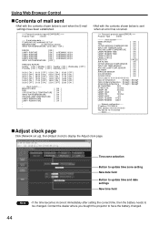
...) === Projector Type : D4000 ----- Using Web Browser Control Contents of mail sent • Mail with the contents shown below is sent when an error has occurred. === Panasonic projector report(ERROR) === Projector Type : D4000 ----- Network configuration ----IP address 192.168.0.8 MAC address 00:00:00:00:00:00 Thu Mar 02 14:11:02 2006 ----- check system ----MAIN CPU BUS FAN OPTICS MODULE TEMPERATURE INPUT AIR TEMPERATURE AROUND LAMP TEMPERATURE LAMP2 REMAIN TIME...
...) === Projector Type : D4000 ----- Using Web Browser Control Contents of mail sent • Mail with the contents shown below is sent when an error has occurred. === Panasonic projector report(ERROR) === Projector Type : D4000 ----- Network configuration ----IP address 192.168.0.8 MAC address 00:00:00:00:00:00 Thu Mar 02 14:11:02 2006 ----- check system ----MAIN CPU BUS FAN OPTICS MODULE TEMPERATURE INPUT AIR TEMPERATURE AROUND LAMP TEMPERATURE LAMP2 REMAIN TIME...
Operating Instructions
Page 47
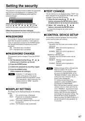
... display the password input screen each time the power is disabled Note • Setting changes will be performed without inputting the correct password. CONTROL PANEL : Operation from the main unit controls can be restricted. To change the setting, input the security password and change at the "ENABLE/DISABLE" menu. PASSWORD CHANGE The password can be changed . Press the ENTER button. (This completes the settings.) Note • Asterisks ( ) will be set and displayed underneath the projected images. LOGO2 : The Panasonic logo is input...
... display the password input screen each time the power is disabled Note • Setting changes will be performed without inputting the correct password. CONTROL PANEL : Operation from the main unit controls can be restricted. To change the setting, input the security password and change at the "ENABLE/DISABLE" menu. PASSWORD CHANGE The password can be changed . Press the ENTER button. (This completes the settings.) Note • Asterisks ( ) will be set and displayed underneath the projected images. LOGO2 : The Panasonic logo is input...
Operating Instructions
Page 50
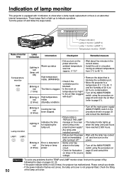
... ? High temperature • Remove the object that the TEMP and LAMP monitor show when a lamp needs replacement or there is an abnormal internal temperature. These lamps flash or light up when turning on • Check for replacing the lamp unit. voltage. 50 Attention • To solve any problems that is inside (refer to page 51). (Standby condition) Lamp monitor LAMP1 LAMP2 Blinking in red (3 times) Lighting in red Blinking in red (3 times), the projector has malfunctioned. High temperature • Check...
... ? High temperature • Remove the object that the TEMP and LAMP monitor show when a lamp needs replacement or there is an abnormal internal temperature. These lamps flash or light up when turning on • Check for replacing the lamp unit. voltage. 50 Attention • To solve any problems that is inside (refer to page 51). (Standby condition) Lamp monitor LAMP1 LAMP2 Blinking in red (3 times) Lighting in red Blinking in red (3 times), the projector has malfunctioned. High temperature • Check...
Operating Instructions
Page 52
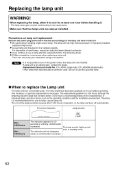
... lamp bursting increases after the replacement time, the lamp may break. The lamp monitor lights up red even in standby mode. 52 Be careful when handling a light source lamp. For disposition of operation, so the lamp unit turns off . If you continue to turn on the power unless two lamp units are installed. • A lamp unit is an optional part. Note • It is recommended for the user to keep a spare lamp unit. The replacement...
... lamp bursting increases after the replacement time, the lamp may break. The lamp monitor lights up red even in standby mode. 52 Be careful when handling a light source lamp. For disposition of operation, so the lamp unit turns off . If you continue to turn on the power unless two lamp units are installed. • A lamp unit is an optional part. Note • It is recommended for the user to keep a spare lamp unit. The replacement...

Operating Instructions
Page 55
... for service --- check the following points. Symptoms Power does not turn on No image Image is blurred Light color/ bad color tone Remote control does not operate Abnormal image Does not display images from PCs Checks • Is the power cord plug correctly plugged in? • Is the MAIN POWER turned on? • Is electricity running to the power outlet? • Is the temperature monitor (TEMP) indicator on the front of the unit flashing or turned...
... for service --- check the following points. Symptoms Power does not turn on No image Image is blurred Light color/ bad color tone Remote control does not operate Abnormal image Does not display images from PCs Checks • Is the power cord plug correctly plugged in? • Is the MAIN POWER turned on? • Is electricity running to the power outlet? • Is the temperature monitor (TEMP) indicator on the front of the unit flashing or turned...

