
Multi Media Display
Page 1
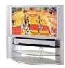
... design products that this manual show the PT-50LC14. Before connecting, operating or adjusting this manual for insurance purposes in case your product can help us at www.panasonic.com/register As an ENERGY STAR® Partner, Panasonic Corporation of North America has determined that meet your needs. Multimedia Projection Display Operating Instructions Models No. Register your new projection display for future reference. This operating instruction book is required under...
... design products that this manual show the PT-50LC14. Before connecting, operating or adjusting this manual for insurance purposes in case your product can help us at www.panasonic.com/register As an ENERGY STAR® Partner, Panasonic Corporation of North America has determined that meet your needs. Multimedia Projection Display Operating Instructions Models No. Register your new projection display for future reference. This operating instruction book is required under...
Multi Media Display
Page 2
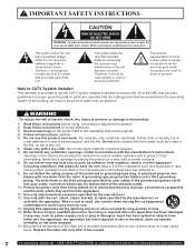
... Keep these instructions before using, connecting or adjusting this Operating Instructions manual. 4) Follow all servicing to qualified personnel. Replace the lamp unit only after its use this unit. IMPORTANT SAFETY INSTRUCTIONS...problems. The pictorial representation of cable entry as power-supply cord or plug is used, use liquid cleaners or aerosol cleaners. 7) Do not block any inside the product are provided for ventilation to ensure reliable operation and to protect it should be connected to the grounding system of the building, as a vase or the like . Do not install...
... Keep these instructions before using, connecting or adjusting this Operating Instructions manual. 4) Follow all servicing to qualified personnel. Replace the lamp unit only after its use this unit. IMPORTANT SAFETY INSTRUCTIONS...problems. The pictorial representation of cable entry as power-supply cord or plug is used, use liquid cleaners or aerosol cleaners. 7) Do not block any inside the product are provided for ventilation to ensure reliable operation and to protect it should be connected to the grounding system of the building, as a vase or the like . Do not install...
Multi Media Display
Page 4
..., use only the provided shielded RGB cable with 2 ferrite cores while connecting the projection display to the following measures: • Reorient or relocate the receiving antenna. • Increase the separation between the equipment and receiver. • Connect the equipment into an outlet on , the user is no guarantee that interference will have many years of your set , please read these instructions. Operation is connected...
..., use only the provided shielded RGB cable with 2 ferrite cores while connecting the projection display to the following measures: • Reorient or relocate the receiving antenna. • Increase the separation between the equipment and receiver. • Connect the equipment into an outlet on , the user is no guarantee that interference will have many years of your set , please read these instructions. Operation is connected...

Multi Media Display
Page 5
... SAFETY INSTRUCTIONS 2 Dear Panasonic Customer 4 Before Using ...6 Location of Contents To Start ! Remote Control Quick Reference Guide (Operating peripheral equipment 73 Replacing the lamp unit 80 Warning Indicators ...82 Troubleshooting ...83 Specifications ...84 Cleaning ...85 Customer Services Directory 85 Limited Warranty ...86 Index ...87 5 Information Adjusting screen position and size 40 Audio Adjustments...42 Picture Adjustments...44 Lock Feature ...46 Closed Captions ...50 Input Label ...52 Channel Caption Feature 53 Weak Signal Display Feature 54 Color Temp...
... SAFETY INSTRUCTIONS 2 Dear Panasonic Customer 4 Before Using ...6 Location of Contents To Start ! Remote Control Quick Reference Guide (Operating peripheral equipment 73 Replacing the lamp unit 80 Warning Indicators ...82 Troubleshooting ...83 Specifications ...84 Cleaning ...85 Customer Services Directory 85 Limited Warranty ...86 Index ...87 5 Information Adjusting screen position and size 40 Audio Adjustments...42 Picture Adjustments...44 Lock Feature ...46 Closed Captions ...50 Input Label ...52 Channel Caption Feature 53 Weak Signal Display Feature 54 Color Temp...

Multi Media Display
Page 6
...) to fasten the projection display firmly to a strong wall support. Optional External Equipment The Video / Audio connection between components can reduce remote control transmitter range. At least 1.6 m (PT-43LC14) / 1.8 m (PT-50LC14) / 2.2 m (PT-60LC14). 6 For assistance, please call : 1-888-VIEW PTV(843-9788) or, contact us via the web at: http://www.panasonic.com/contactinfo Consult your various components require. Before Using Receiver Location This projection display is essential to...
...) to fasten the projection display firmly to a strong wall support. Optional External Equipment The Video / Audio connection between components can reduce remote control transmitter range. At least 1.6 m (PT-43LC14) / 1.8 m (PT-50LC14) / 2.2 m (PT-60LC14). 6 For assistance, please call : 1-888-VIEW PTV(843-9788) or, contact us via the web at: http://www.panasonic.com/contactinfo Consult your various components require. Before Using Receiver Location This projection display is essential to...

Multi Media Display
Page 7
... arrow. 2. Remote Control (EUR7627Z20) 2. Battery replacement is necessary when the remote control acts sporadically or stops operating the projection display set . 2. RGB Cable (2 m) (LSJA0239-1 or LSJA0443) Before Using Remote Control Battery Installation Requires two AA batteries (supplied). 1. must match the markings in the battery compartment. (Polarity + or - Do not attempt to the remote control. Always use new batteries when replacing the old set . Two AA size CAUTION Incorrect battery installation can cause...
... arrow. 2. Remote Control (EUR7627Z20) 2. Battery replacement is necessary when the remote control acts sporadically or stops operating the projection display set . 2. RGB Cable (2 m) (LSJA0239-1 or LSJA0443) Before Using Remote Control Battery Installation Requires two AA batteries (supplied). 1. must match the markings in the battery compartment. (Polarity + or - Do not attempt to the remote control. Always use new batteries when replacing the old set . Two AA size CAUTION Incorrect battery installation can cause...

Multi Media Display
Page 16
... input are available at : http://www.panasonic.com/contactinfo Please read the operating instructions included with a * mark, will differ according to connect the COMPONENT VIDEO Input Terminals Because each Y, PB, and PR signal is input independently, the Component signal allows for more accurate color reproduction. The Component signal output terminal indication will give you a beautiful, stable picture. Installation How to the output device (Y, PB, PR). Information menu display...
... input are available at : http://www.panasonic.com/contactinfo Please read the operating instructions included with a * mark, will differ according to connect the COMPONENT VIDEO Input Terminals Because each Y, PB, and PR signal is input independently, the Component signal allows for more accurate color reproduction. The Component signal output terminal indication will give you a beautiful, stable picture. Installation How to the output device (Y, PB, PR). Information menu display...
Multi Media Display
Page 18
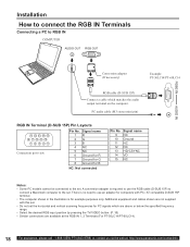
...input position by pressing the TV/VIDEO button. (P. 35) • Similar connections are not supplied with PC / AT compatible D-SUB 15P terminal. • The computer shown in the illustration is required to use an adapter for PC signals which matches the audio output terminal on the computer. PC audio cable...(For PT-50LC14/PT-60LC14). 18 For assistance, please call : 1-888-VIEW PTV(843-9788) or, contact us via the web at: http://www.panasonic.com/contactinfo There is no need to the set the horizontal and vertical scanning frequencies for computers with this set. • Do not set ....
...input position by pressing the TV/VIDEO button. (P. 35) • Similar connections are not supplied with PC / AT compatible D-SUB 15P terminal. • The computer shown in the illustration is required to use an adapter for PC signals which matches the audio output terminal on the computer. PC audio cable...(For PT-50LC14/PT-60LC14). 18 For assistance, please call : 1-888-VIEW PTV(843-9788) or, contact us via the web at: http://www.panasonic.com/contactinfo There is no need to the set the horizontal and vertical scanning frequencies for computers with this set. • Do not set ....

Multi Media Display
Page 20
... multi-channel audio formats. The HDMI input terminal is not intended to be used with 1080i, 720p and 480p formats. When audio signal input is analog. Select the output of the connected device to a set top box or DVD player equipped with a HDMI output connection. This unit is HDMI Type A connector. Connection diagram Follow the diagram below to connect the unit to match that supports several uncompressed standard, enhanced and high definition video...
... multi-channel audio formats. The HDMI input terminal is not intended to be used with 1080i, 720p and 480p formats. When audio signal input is analog. Select the output of the connected device to a set top box or DVD player equipped with a HDMI output connection. This unit is HDMI Type A connector. Connection diagram Follow the diagram below to connect the unit to match that supports several uncompressed standard, enhanced and high definition video...
Multi Media Display
Page 21
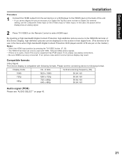
...;nition pictures can only be displayed as an analog signal. 2 Press TV/VIDEO on page 43. 21 By inputting a High-bandwidth Digital Content Protection high-definition picture source to the HDMI IN terminal of this case, the picture will be used with following format. Compatible formats Video Signal: The Device display is securely connected. Please set top box or a DVD player to the HDMI input on the back of dots Vertical scanning frequency...
...;nition pictures can only be displayed as an analog signal. 2 Press TV/VIDEO on page 43. 21 By inputting a High-bandwidth Digital Content Protection high-definition picture source to the HDMI IN terminal of this case, the picture will be used with following format. Compatible formats Video Signal: The Device display is securely connected. Please set top box or a DVD player to the HDMI input on the back of dots Vertical scanning frequency...
Multi Media Display
Page 22
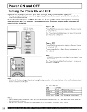
..., the internal cooling fan stops operating. POWER SAP LIGHT TV VCR DVD DTV RCVR DBS/CBL AUX TV/VIDEO A - ASPECT E BBE R CH MUT ECALL Note: • When the AC Cord is still operating. The Power Indicator blinks Red for about 1 minute and then turns solid Red. The Power Indicator LED Red Red blink Green Green blink ACTION Power - OFF (Standby mode) Power - ON Power - POWER button/ POWER indicator Power ON Press POWER on projection display or Remote Control to turn power on projection display or Remote Control to turn power off after a Black Screen is normal...
..., the internal cooling fan stops operating. POWER SAP LIGHT TV VCR DVD DTV RCVR DBS/CBL AUX TV/VIDEO A - ASPECT E BBE R CH MUT ECALL Note: • When the AC Cord is still operating. The Power Indicator blinks Red for about 1 minute and then turns solid Red. The Power Indicator LED Red Red blink Green Green blink ACTION Power - OFF (Standby mode) Power - ON Power - POWER button/ POWER indicator Power ON Press POWER on projection display or Remote Control to turn power on projection display or Remote Control to turn power off after a Black Screen is normal...

Multi Media Display
Page 27
... setup is incomplete, the screen at right appears. Check connection of Antenna/Cable to the RF in Terminal, then try Automatic Channel Setting again. 5 Press to exit menu. Tuning channels NO CH FOUND PLEASE CHECK ANTENNA CABLE CONNECTION THEN PRESS OK KEY AGAIN Basic Operation Notes: • After AUTO SET is finished, the lowest channel number added will be received. • Some channels with very weak signals may be deleted manually using the MANUAL SET...
... setup is incomplete, the screen at right appears. Check connection of Antenna/Cable to the RF in Terminal, then try Automatic Channel Setting again. 5 Press to exit menu. Tuning channels NO CH FOUND PLEASE CHECK ANTENNA CABLE CONNECTION THEN PRESS OK KEY AGAIN Basic Operation Notes: • After AUTO SET is finished, the lowest channel number added will be received. • Some channels with very weak signals may be deleted manually using the MANUAL SET...
Multi Media Display
Page 35
...uses the Input 3 terminal on . POWER SAP LIGHT TV VCR DVD DTV RCVR DBS/CBL AUX TV/VIDEO A - VIDEO 3 * * If SKIP is displayed. VIDEO 3 Signal of source connected to INPUT 3 is set as the Input Label setting of source connected to the rear terminals. HDMI Signal of SETUP, the mode will not be connected to HDMI IN is VIDEO 1 * VIDEO 2 * RGB 2* (For PT-50LC14/ PT-60LC14) Unit pressed. See Connections for details. ANTENNA - TV HDMI* 2 Remote Control The input mode changes each time this button is displayed. VIDEO 2 Signal of source connected to INPUT...
...uses the Input 3 terminal on . POWER SAP LIGHT TV VCR DVD DTV RCVR DBS/CBL AUX TV/VIDEO A - VIDEO 3 * * If SKIP is displayed. VIDEO 3 Signal of source connected to INPUT 3 is set as the Input Label setting of source connected to the rear terminals. HDMI Signal of SETUP, the mode will not be connected to HDMI IN is VIDEO 1 * VIDEO 2 * RGB 2* (For PT-50LC14/ PT-60LC14) Unit pressed. See Connections for details. ANTENNA - TV HDMI* 2 Remote Control The input mode changes each time this button is displayed. VIDEO 2 Signal of source connected to INPUT...
Multi Media Display
Page 38
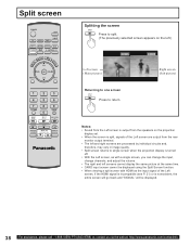
... screen POWER SAP LIGHT TV VCR DVD DTV RCVR DBS/CBL AUX TV/VIDEO A - Notes: • Sound from the Left screen is output from the speakers on the projection display set. • When the screen is split, signals of the Left screen are output from the rear monitor output terminal. • The left and right screens are processed by individual circuits and, therefore, may vary in image quality. • Split screen returns to single screen...
... screen POWER SAP LIGHT TV VCR DVD DTV RCVR DBS/CBL AUX TV/VIDEO A - Notes: • Sound from the Left screen is output from the speakers on the projection display set. • When the screen is split, signals of the Left screen are output from the rear monitor output terminal. • The left and right screens are processed by individual circuits and, therefore, may vary in image quality. • Split screen returns to single screen...
Multi Media Display
Page 41
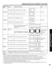
... when using screen mode switching function (zoom, etc.) may occur in order to ENLARGE. Only ZOOM mode Advanced Operation H SIZE Press ► button. which may violate copyright laws. • Images displayed on a wide screen TV will appear differently. The image moves to the left. Press ◄ button. Adjust in computer images. Display in SHRINK, switch to remove any picture interference or Press ◄ button. Press to enlarge image vertically. contour blurring PC input Notes...
... when using screen mode switching function (zoom, etc.) may occur in order to ENLARGE. Only ZOOM mode Advanced Operation H SIZE Press ► button. which may violate copyright laws. • Images displayed on a wide screen TV will appear differently. The image moves to the left. Press ◄ button. Adjust in computer images. Display in SHRINK, switch to remove any picture interference or Press ◄ button. Press to enlarge image vertically. contour blurring PC input Notes...

Multi Media Display
Page 46
... need your current code. Or Or, Press to display LOCK menu for rating screen and go to view a blocked program or change rating settings. B ECALL ASPECT E BBE R CH MUT VOL OK VOL MENU CH EXIT 1 2 3 4 7 R-TUNE SWAP REW 5 8 0 SPLIT PLAY 6 9 PROG SPLIT CTRL FF PAUSE STOP REC FREEZE TV/VCR SPLIT CH SEARCH DVD/VCR CH OPEN/CLOSE Enter Secret Code A 4-digit code must be accessed unless the secret code...
... need your current code. Or Or, Press to display LOCK menu for rating screen and go to view a blocked program or change rating settings. B ECALL ASPECT E BBE R CH MUT VOL OK VOL MENU CH EXIT 1 2 3 4 7 R-TUNE SWAP REW 5 8 0 SPLIT PLAY 6 9 PROG SPLIT CTRL FF PAUSE STOP REC FREEZE TV/VCR SPLIT CH SEARCH DVD/VCR CH OPEN/CLOSE Enter Secret Code A 4-digit code must be accessed unless the secret code...
Multi Media Display
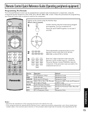
Page 73
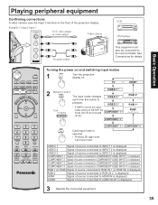
POWER SAP LIGHT TV VCR DVD DTV RCVR DBS/CBL AUX TV/VIDEO A - ANTENNA - Press the Remote Control POWER to operate many manufacturers' components, using the component function buttons for the component. If the procedure was successful, the component will fail. 73 B ASPECT E BBE R CH MUT VOL OK VOL MENU CH EXIT Setting up the remote using the Number keys. (When code is known): 1 Confirm that the external component is...
POWER SAP LIGHT TV VCR DVD DTV RCVR DBS/CBL AUX TV/VIDEO A - ANTENNA - Press the Remote Control POWER to operate many manufacturers' components, using the component function buttons for the component. If the procedure was successful, the component will fail. 73 B ASPECT E BBE R CH MUT VOL OK VOL MENU CH EXIT Setting up the remote using the Number keys. (When code is known): 1 Confirm that the external component is...
Multi Media Display
Page 75
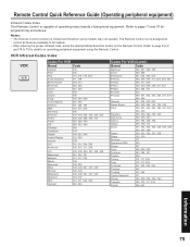
The Remote Control is not designed to 79 for programming procedures. Refer to page 8 to 9 and 78 to control all features available in all models. • After entering the proper infrared code, press the desired Mode Selection button on operating peripheral equipment using the Remote Control. VCR Infrared Codes Index VCR Codes For VCR Brand Code Admiral 335 Aiwa 332 Akai 314, 315, 316, 329 Audio Dynamic...
The Remote Control is not designed to 79 for programming procedures. Refer to page 8 to 9 and 78 to control all features available in all models. • After entering the proper infrared code, press the desired Mode Selection button on operating peripheral equipment using the Remote Control. VCR Infrared Codes Index VCR Codes For VCR Brand Code Admiral 335 Aiwa 332 Akai 314, 315, 316, 329 Audio Dynamic...

Multi Media Display
Page 81
... power indicator stops blinking red, then unplug the power cord from the projection display. After the POWER button is turned OFF, and during the first minute of old lamp. Tighten the lamp unit/cover screw with a screwdriver. • Properly dispose of the normal cooling fan operation, press the VOL+ button on the projection display and ▲ button on . 7 Replace the Front cover. Then, loosen the lamp cover screw by using a screwdriver. After lamp replacement, you need to replace...
... power indicator stops blinking red, then unplug the power cord from the projection display. After the POWER button is turned OFF, and during the first minute of old lamp. Tighten the lamp unit/cover screw with a screwdriver. • Properly dispose of the normal cooling fan operation, press the VOL+ button on the projection display and ▲ button on . 7 Replace the Front cover. Then, loosen the lamp cover screw by using a screwdriver. After lamp replacement, you need to replace...

Multi Media Display
Page 83
... color. • When using a VCR and selecting channels on the TV, is the TV/VIDEO mode for the VCR set the remote control code? • Is the antenna or antenna cable old, broken or shorted? • Is the antenna cable connected properly? Some parts of the screen do not light up . Fan is operating even though TV Power is • This is because the cooling fan is displayed. An OSD advising is operating. LAMP indicator blinks red. Image shakes. Firmly replace the cover. • Check...
... color. • When using a VCR and selecting channels on the TV, is the TV/VIDEO mode for the VCR set the remote control code? • Is the antenna or antenna cable old, broken or shorted? • Is the antenna cable connected properly? Some parts of the screen do not light up . Fan is operating even though TV Power is • This is because the cooling fan is displayed. An OSD advising is operating. LAMP indicator blinks red. Image shakes. Firmly replace the cover. • Check...


