Multi-media Display
Page 3
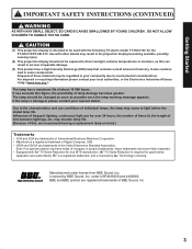
If use for good stereo separation and audio fidelity. may result in the projection display becoming unstable, possibly causing injury. (2) This projection display should be exposed to direct sunlight, extreme temperatures or moisture, as possible once the lamp warning ... Industries Alliance: The lamp has a maximum life of individual lamps, the lamp may be used with -TV Noise Reduction for the PT-50LC13/PT-60LC13. is a registered trademark, and is intended to be regulated in some components. CAUTION (1) This projection display is licensed by BBE Sound, Inc.
If use for good stereo separation and audio fidelity. may result in the projection display becoming unstable, possibly causing injury. (2) This projection display should be exposed to direct sunlight, extreme temperatures or moisture, as possible once the lamp warning ... Industries Alliance: The lamp has a maximum life of individual lamps, the lamp may be used with -TV Noise Reduction for the PT-50LC13/PT-60LC13. is a registered trademark, and is intended to be regulated in some components. CAUTION (1) This projection display is licensed by BBE Sound, Inc.

Multi-media Display
Page 4
...rear cover of the FCC Rules. Address: One Panasonic Way Secaucus New Jersey 07094 Telephone number: 1-888-VIEW PTV(843-9788) This device complies with 2 ferrite cores while connecting the projection display to the Panasonic... family of the FCC Rules. Operation is connected. • Consult the dealer or an experienced radio / TV technician for help. Visit our Panasonic...instructions. Declaration of Conformity Models Number: PT-50LC13/PT-60LC13 Trade Name: Panasonic Responsible party: Matsushita Electric Corporation of your purchase receipt also...
...rear cover of the FCC Rules. Address: One Panasonic Way Secaucus New Jersey 07094 Telephone number: 1-888-VIEW PTV(843-9788) This device complies with 2 ferrite cores while connecting the projection display to the Panasonic... family of the FCC Rules. Operation is connected. • Consult the dealer or an experienced radio / TV technician for help. Visit our Panasonic...instructions. Declaration of Conformity Models Number: PT-50LC13/PT-60LC13 Trade Name: Panasonic Responsible party: Matsushita Electric Corporation of your purchase receipt also...

Multi-media Display
Page 8
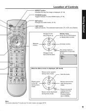
Location of Controls Illuminated Remote Control POWER button Press to turn the projection display ON or OFF. (P. 22) MUTE button Press this button to mute the sound. (P. 36) Mode Selection buttons Selects the operation mode for the remote ... for Remote Control AUX Mode Selection for Remote Control Receiver / Amplifier Mode Selection for Remote Control Digital Broadcasting Satellite for Remote Control Cable TV Mode Selection for Remote Control PC/MENU button RGB input mode is displayed in single screen. (P. 31) R-TUNE button Press to view previous channel or...
Location of Controls Illuminated Remote Control POWER button Press to turn the projection display ON or OFF. (P. 22) MUTE button Press this button to mute the sound. (P. 36) Mode Selection buttons Selects the operation mode for the remote ... for Remote Control AUX Mode Selection for Remote Control Receiver / Amplifier Mode Selection for Remote Control Digital Broadcasting Satellite for Remote Control Cable TV Mode Selection for Remote Control PC/MENU button RGB input mode is displayed in single screen. (P. 31) R-TUNE button Press to view previous channel or...
Multi-media Display
Page 9
...screen below is displayed for 5 seconds. (P. 31) NORMAL STEREO SAP MONO CH 1 2 ABC When the Menu screen is displayed. (P. 32) TV/VIDEO button Toggles between TV and VIDEO inputs. (P. 35) SAP button Changes the audio mode. (P. 37) Light button Lights all buttons. Returns to display Menu screen. Previous... the items. Moves cursor to the right during menu mode. Moves cursor to the left during menu mode. Note: This section describes TV mode only. Changes to the next channel down. Changes to the next channel up. Getting Started Location of Controls ASPECT button Changes the...
...screen below is displayed for 5 seconds. (P. 31) NORMAL STEREO SAP MONO CH 1 2 ABC When the Menu screen is displayed. (P. 32) TV/VIDEO button Toggles between TV and VIDEO inputs. (P. 35) SAP button Changes the audio mode. (P. 37) Light button Lights all buttons. Returns to display Menu screen. Previous... the items. Moves cursor to the right during menu mode. Moves cursor to the left during menu mode. Note: This section describes TV mode only. Changes to the next channel down. Changes to the next channel up. Getting Started Location of Controls ASPECT button Changes the...
Multi-media Display
Page 13
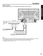
... supplied by your local Cable company for proper reception. Antenna Mode must be set to a cable TV system. Installation Cable Connection Use this configuration when connecting the projection display to CABLE. (P. 26) 13 Check with your local cable company. A cable converter box ...is required for its compatibility requirements. • For reception of the projection display. In from the antenna or cable system to...
... supplied by your local Cable company for proper reception. Antenna Mode must be set to a cable TV system. Installation Cable Connection Use this configuration when connecting the projection display to CABLE. (P. 26) 13 Check with your local cable company. A cable converter box ...is required for its compatibility requirements. • For reception of the projection display. In from the antenna or cable system to...

Multi-media Display
Page 14
Installation Connecting the Antenna / Cable to the RF in Terminal (VCR) Use this configuration when connecting the projection display to the Antenna input terminal on the back of the Cable Box or antenna/cable system to a cable TV system using VCR. This does not apply when signal is connected to the... projection display VHF/UHF terminal via a cable box or VCR, set the TV channel to CH3 or CH4. VCR In from cable TERMINAL ON THE BACK...
Installation Connecting the Antenna / Cable to the RF in Terminal (VCR) Use this configuration when connecting the projection display to the Antenna input terminal on the back of the Cable Box or antenna/cable system to a cable TV system using VCR. This does not apply when signal is connected to the... projection display VHF/UHF terminal via a cable box or VCR, set the TV channel to CH3 or CH4. VCR In from cable TERMINAL ON THE BACK...
Multi-media Display
Page 15
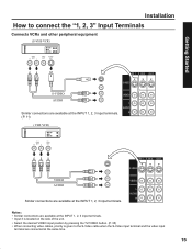
... at the INPUT 1, 2, 3 input terminals. • Input 3 is located on the side of the unit. • Select the desired VIDEO input position by pressing the TV/VIDEO button. (P. 35) • When connecting video cables, priority is given to connect the "1, 2, 3" Input Terminals Connects VCRs and other peripheral equipment (S-VHS VCR) S-VIDEO...
... at the INPUT 1, 2, 3 input terminals. • Input 3 is located on the side of the unit. • Select the desired VIDEO input position by pressing the TV/VIDEO button. (P. 35) • When connecting video cables, priority is given to connect the "1, 2, 3" Input Terminals Connects VCRs and other peripheral equipment (S-VHS VCR) S-VIDEO...

Multi-media Display
Page 16
... (Y, PB, PR) that can be input are available at the COMPONENT VIDEO INPUT 1-4 Terminals. • Select the desired COMPONENT VIDEO INPUT position by pressing the TV/VIDEO button. (P. 35) • Component video signals that can be Input Mode type 480i No. Installation How to the output device (Y, PB, PR).
... (Y, PB, PR) that can be input are available at the COMPONENT VIDEO INPUT 1-4 Terminals. • Select the desired COMPONENT VIDEO INPUT position by pressing the TV/VIDEO button. (P. 35) • Component video signals that can be Input Mode type 480i No. Installation How to the output device (Y, PB, PR).
Multi-media Display
Page 17
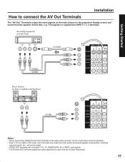
...; The S-Video OUT terminal outputs the same signal that time, e.g. Getting Started Installation How to the same video recorder, as the main picture on the projection display screen and sound from the speaker at that is in Split or PIP mode, OUT terminals only output the main picture and sound signals... OUT terminals to connect the AV Out Terminals The "AV Out" Terminals output the same signals as this could cause incorrect operation. • Even if TV is input from INPUT 1, 2, 3 terminals. TV programs or signals from the S-Video IN terminal. 17
...; The S-Video OUT terminal outputs the same signal that time, e.g. Getting Started Installation How to the same video recorder, as the main picture on the projection display screen and sound from the speaker at that is in Split or PIP mode, OUT terminals only output the main picture and sound signals... OUT terminals to connect the AV Out Terminals The "AV Out" Terminals output the same signals as this could cause incorrect operation. • Even if TV is input from INPUT 1, 2, 3 terminals. TV programs or signals from the S-Video IN terminal. 17
Multi-media Display
Page 18
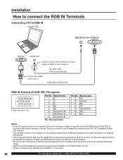
... signals which are above or below the specified frequency range. • Select the desired RGB input position by pressing the PC/MENU or TV/VIDEO button. (P. 35) • Similar connections are not supplied with this set. • The picture will become dark if an PC signal with a ...available at the RGB IN 1, 2 Terminals. 18 For assistance, please call : 1-888-VIEW PTV(843-9788) To obtain the optimum picture quality with the projection display, a vertical scanning frequency of 62 Hz is no need to RGB IN COMPUTER RGB OUT AUDIO OUT Connect a cable which matches the audio output...
... signals which are above or below the specified frequency range. • Select the desired RGB input position by pressing the PC/MENU or TV/VIDEO button. (P. 35) • Similar connections are not supplied with this set. • The picture will become dark if an PC signal with a ...available at the RGB IN 1, 2 Terminals. 18 For assistance, please call : 1-888-VIEW PTV(843-9788) To obtain the optimum picture quality with the projection display, a vertical scanning frequency of 62 Hz is no need to RGB IN COMPUTER RGB OUT AUDIO OUT Connect a cable which matches the audio output...
Multi-media Display
Page 19
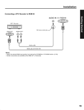
Getting Started Connecting a DTV Decoder to RGB IN DTV Decoder RGB OUT AUDIO OUT M3 stereo mini pin Installation Audio cable RGB cable (D-SUB 15P) Notes: • Select the desired RGB input position by pressing the PC/MENU or TV/VIDEO button. (P. 35) • Similar connections are available at the RGB IN 1, 2 Terminals. 19
Getting Started Connecting a DTV Decoder to RGB IN DTV Decoder RGB OUT AUDIO OUT M3 stereo mini pin Installation Audio cable RGB cable (D-SUB 15P) Notes: • Select the desired RGB input position by pressing the PC/MENU or TV/VIDEO button. (P. 35) • Similar connections are available at the RGB IN 1, 2 Terminals. 19
Multi-media Display
Page 20
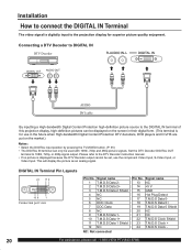
Set the DTV Decoder DIGITAL OUT terminal to the projection display for use the component Video Input, S-Video Input, or Video Input. Signal name 13 NC...used with 1080i, 720p and 480p picture signals. Please refer to the DIGITAL IN terminal of this projection display, high-definition pictures can be displayed on the market.) Notes: • Select the DIGITAL input ...position by pressing the TV/VIDEO button. (P. 35) • The DIGITAL IN terminal can only be set, use in the future when...
Set the DTV Decoder DIGITAL OUT terminal to the projection display for use the component Video Input, S-Video Input, or Video Input. Signal name 13 NC...used with 1080i, 720p and 480p picture signals. Please refer to the DIGITAL IN terminal of this projection display, high-definition pictures can be displayed on the market.) Notes: • Select the DIGITAL input ...position by pressing the TV/VIDEO button. (P. 35) • The DIGITAL IN terminal can only be set, use in the future when...
Multi-media Display
Page 26
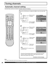
... CHANNEL. Continued on the next page. LANGUAGE :ENGLISH CHANNEL LOCK CAPTION VIDEO OTHER Press to select AUTO SET. Press to select TV or CABLE. 3 Press to display the CHANNEL. Note: TV or Cable Tuning mode must be stored in progress, press the SWAP button. Note: To cancel AUTO SET in the channel...
... CHANNEL. Continued on the next page. LANGUAGE :ENGLISH CHANNEL LOCK CAPTION VIDEO OTHER Press to select AUTO SET. Press to select TV or CABLE. 3 Press to display the CHANNEL. Note: TV or Cable Tuning mode must be stored in progress, press the SWAP button. Note: To cancel AUTO SET in the channel...
Multi-media Display
Page 28
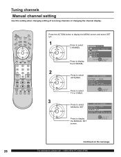
... DISPLAY:OFF Press to select ADJUST SET UP CHANNEL. Press the ACTION button to display the MENU screen and select SET UP. 1 Press to select TV or CABLE. SELECT EXIT Continued on the next page. 28 For assistance, please call : 1-888-VIEW PTV(843-9788) Tuning channels Manual channel setting Use...
... DISPLAY:OFF Press to select ADJUST SET UP CHANNEL. Press the ACTION button to display the MENU screen and select SET UP. 1 Press to select TV or CABLE. SELECT EXIT Continued on the next page. 28 For assistance, please call : 1-888-VIEW PTV(843-9788) Tuning channels Manual channel setting Use...

Multi-media Display
Page 30
.../ POWER indicator Volume up(+) / down(-) buttons Remote Control Sensor 1 Channel up / down buttons Press to operate the projection display with the remote control. 2 Press to turn the projection display on. 3 Press to select CABLE TV 125 or 69 the desired CH 01 channel. (Or use number keys ) CH 02 Or CH 125 Note...
.../ POWER indicator Volume up(+) / down(-) buttons Remote Control Sensor 1 Channel up / down buttons Press to operate the projection display with the remote control. 2 Press to turn the projection display on. 3 Press to select CABLE TV 125 or 69 the desired CH 01 channel. (Or use number keys ) CH 02 Or CH 125 Note...
Multi-media Display
Page 31
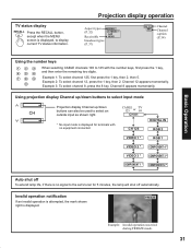
...lamp will shut off automatically. Invalid operation notification If an invalid operation is attempted, the mark shown right is displayed, to display current TV status information. Example 2: To select channel 12, press the 1 key, then 2. Channel 12 appears momentarily. Example 3: To select channel 8,... to the set's tuner for terminals with the number keys, first press the 1 key, and then enter the remaining two digits. Projection display operation Aspect types (P. 32) Receivable broadcast types (P. 37) NORMAL STEREO SAP MONO CH 1 2 ABC Channel Channel caption (P. 54)...
...lamp will shut off automatically. Invalid operation notification If an invalid operation is attempted, the mark shown right is displayed, to display current TV status information. Example 2: To select channel 12, press the 1 key, then 2. Channel 12 appears momentarily. Example 3: To select channel 8,... to the set's tuner for terminals with the number keys, first press the 1 key, and then enter the remaining two digits. Projection display operation Aspect types (P. 32) Receivable broadcast types (P. 37) NORMAL STEREO SAP MONO CH 1 2 ABC Channel Channel caption (P. 54)...

Multi-media Display
Page 35
...details. VIDEO 2 Signal of source connected to DIGITAL IN is displayed. CARD Signal of source connected to the rear terminals. TV CARD VIDEO 1 * DIGITAL IN 2 The input mode changes each time this button is VIDEO 2 * ...projection display on the front of source connected to COMPONENT VIDEO INPUT 4 is selected. VIDEO 3 * COMPONENT 1 * Card input mode is displayed. DIGITAL IN Signal of source connected to RGB IN 1 is displayed. 3 Operate the connected equipment. 35 COMPONENT 4 Signal of source connected to CARD SLOT is displayed. RGB 1 Signal of the projection...
...details. VIDEO 2 Signal of source connected to DIGITAL IN is displayed. CARD Signal of source connected to the rear terminals. TV CARD VIDEO 1 * DIGITAL IN 2 The input mode changes each time this button is VIDEO 2 * ...projection display on the front of source connected to COMPONENT VIDEO INPUT 4 is selected. VIDEO 3 * COMPONENT 1 * Card input mode is displayed. DIGITAL IN Signal of source connected to RGB IN 1 is displayed. 3 Operate the connected equipment. 35 COMPONENT 4 Signal of source connected to CARD SLOT is displayed. RGB 1 Signal of the projection...
Multi-media Display
Page 37
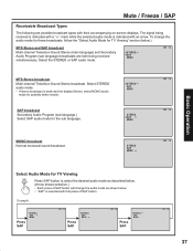
...CH 1 2 37 Select the STEREO or SAP audio mode. To change the audio mode for these broadcasts, follow the "Select Audio Mode for TV Viewing Press SAP button to select the desired audio mode as described below. (Arrow shows selection.) • Each press of SAP button. Select ...STEREO SAP MONO STEREO SAP MONO CH 1 2 CH 1 2 MONO broadcast Normal monaural sound broadcast. STEREO SAP MONO CH 1 2 Basic Operation Select Audio Mode for TV Viewing" section (below . • "SAP" is weak and the display flickers, select MONO audio mode for the sub language. Mute / Freeze / SAP ...
...CH 1 2 37 Select the STEREO or SAP audio mode. To change the audio mode for these broadcasts, follow the "Select Audio Mode for TV Viewing Press SAP button to select the desired audio mode as described below. (Arrow shows selection.) • Each press of SAP button. Select ...STEREO SAP MONO STEREO SAP MONO CH 1 2 CH 1 2 MONO broadcast Normal monaural sound broadcast. STEREO SAP MONO CH 1 2 Basic Operation Select Audio Mode for TV Viewing" section (below . • "SAP" is weak and the display flickers, select MONO audio mode for the sub language. Mute / Freeze / SAP ...
Multi-media Display
Page 39
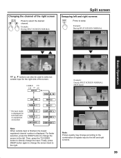
... or 69 CH 01 DIGITAL IN CH 125 RGB 2 VIDEO 1 * RGB 1 * No input mode is displayed. Then, press the TV/VIDEO button to directly change the screen back to the right. Finally, press SWAP button again to the left. Example: During SPLIT SCREEN NORMAL (RGB ...
... or 69 CH 01 DIGITAL IN CH 125 RGB 2 VIDEO 1 * RGB 1 * No input mode is displayed. Then, press the TV/VIDEO button to directly change the screen back to the right. Finally, press SWAP button again to the left. Example: During SPLIT SCREEN NORMAL (RGB ...

Multi-media Display
Page 43
...vertically Only ZOOM mode Press ◄ button. which may violate copyright laws. • Images displayed on a wide screen TV will be kept even when the projection display is adjusted. 43 Adjusting screen position and size Adjustment Button Adjustment Details item H Position Press ► button. Adjust... SIZE Press ► button. If a screen mode with a different aspect from the monitor output terminal on the back of the projection display is not affected when the screen size and position is turned off or distorted at the edges, when viewing normal aspect images...
...vertically Only ZOOM mode Press ◄ button. which may violate copyright laws. • Images displayed on a wide screen TV will be kept even when the projection display is adjusted. 43 Adjusting screen position and size Adjustment Button Adjustment Details item H Position Press ► button. Adjust... SIZE Press ► button. If a screen mode with a different aspect from the monitor output terminal on the back of the projection display is not affected when the screen size and position is turned off or distorted at the edges, when viewing normal aspect images...


