Service Manual
Page 1
CF-74GCDADBM This is a violation of law. M ...for the following areas. All rights reserved. CPD0705211C3 Notebook Computer Model No. and Canada © 2007 Matsushita Electric Industrial Co., Ltd. Unauthorized copying and distribution is the Service Manual for U.S.A. ORDER NO.
CF-74GCDADBM This is a violation of law. M ...for the following areas. All rights reserved. CPD0705211C3 Notebook Computer Model No. and Canada © 2007 Matsushita Electric Industrial Co., Ltd. Unauthorized copying and distribution is the Service Manual for U.S.A. ORDER NO.
Service Manual
Page 7
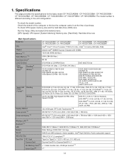
... Smart Card*18 x 1 1-1 CF-74GCDADBM / CF-74GCDCDBM / CF-74GCDEDBM / CF-74HCDAZBM CF-74GCDBDBM / CF-74GCDDDBM / CF-74GCDFDBM / CF-74HCDBZBM CPU Intel® Core™ 2 Duo Processor T7300 (2.0 GHz, 4 MB*1 L2 cache, 800 MHz FSB) Chipset Mobile Intel® GM965 Express Chipsets with ICH8M Memory*1*2 1024 MB (4096 MB Max.) Video Memory*1*3 UMA (384 MB Max.) Hard Disk Drive*4 80 GB CD/DVD Drive DVD-ROM & CD-R/RW Drive DVD MULTI Drive Data Transfer Rate*5 Reading*6 Writing*7 DVD-ROM: 8X...
... Smart Card*18 x 1 1-1 CF-74GCDADBM / CF-74GCDCDBM / CF-74GCDEDBM / CF-74HCDAZBM CF-74GCDBDBM / CF-74GCDDDBM / CF-74GCDFDBM / CF-74HCDBZBM CPU Intel® Core™ 2 Duo Processor T7300 (2.0 GHz, 4 MB*1 L2 cache, 800 MHz FSB) Chipset Mobile Intel® GM965 Express Chipsets with ICH8M Memory*1*2 1024 MB (4096 MB Max.) Video Memory*1*3 UMA (384 MB Max.) Hard Disk Drive*4 80 GB CD/DVD Drive DVD-ROM & CD-R/RW Drive DVD MULTI Drive Data Transfer Rate*5 Reading*6 Writing*7 DVD-ROM: 8X...
Service Manual
Page 8
... allotted automatically depending on the actual system configuration. *3 A segment of usable memory available will report as fewer GB. 1-2 Your operating system or some application software will be set by TOSHIBA*14, Wireless Switch Utility, Hotkey Settings, Battery Recalibration Utility, LAN Power-Saving Utility, Infineon TPM Professional Package*26, Recover Pro™ 6*26 Setup Utility, PC-Diagnostic Utility, Hard Disk Data Erase Utility*27 Wireless LAN Intel® Wireless WiFi link 4965 AGN (802.11 a + b + g)*28 PCI Ex...
... allotted automatically depending on the actual system configuration. *3 A segment of usable memory available will report as fewer GB. 1-2 Your operating system or some application software will be set by TOSHIBA*14, Wireless Switch Utility, Hotkey Settings, Battery Recalibration Utility, LAN Power-Saving Utility, Infineon TPM Professional Package*26, Recover Pro™ 6*26 Setup Utility, PC-Diagnostic Utility, Hard Disk Data Erase Utility*27 Wireless LAN Intel® Wireless WiFi link 4965 AGN (802.11 a + b + g)*28 PCI Ex...
Service Manual
Page 9
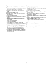
... energy efficiency. *25 Rated power consumption 23-E-1 *26 You need to install to use a card that supports the higher transfer rate. *18 Only for model with Bluetooth *15 For information on the specifications of the external display. *13 Only for model with wireless LAN *14 Only for model with Smart Card slot *19 The AC adaptor is compatible with the LAN Power-saving functions Auto-off setting set to 240 V AC adaptor...
... energy efficiency. *25 Rated power consumption 23-E-1 *26 You need to install to use a card that supports the higher transfer rate. *18 Only for model with Bluetooth *15 For information on the specifications of the external display. *13 Only for model with wireless LAN *14 Only for model with Smart Card slot *19 The AC adaptor is compatible with the LAN Power-saving functions Auto-off setting set to 240 V AC adaptor...

Service Manual
Page 10
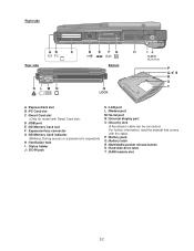
... Q :Wireless switch 2-1 When they are used . If other types H :LCD I C D O E P F Q A :Speaker J : Power switch B :USB port K :Function key C :Stylus holder L : Bluetooth antenna D :Multimedia pocket E : Hard disk drive M :Keyboard F : Carrying handle N :Touch pad G :Wireless LAN antenna O :Microphone jack A condenser microphone can connect headphones or amplified speakers. Otherwise, only audio on , Blink- Names and Functions of Parts G H I J K A A L M N B I : LED indicator of microphones are connected, audio from the internal speakers...
... Q :Wireless switch 2-1 When they are used . If other types H :LCD I C D O E P F Q A :Speaker J : Power switch B :USB port K :Function key C :Stylus holder L : Bluetooth antenna D :Multimedia pocket E : Hard disk drive M :Keyboard F : Carrying handle N :Touch pad G :Wireless LAN antenna O :Microphone jack A condenser microphone can connect headphones or amplified speakers. Otherwise, only audio on , Blink- Names and Functions of Parts G H I J K A A L M N B I : LED indicator of microphones are connected, audio from the internal speakers...
Service Manual
Page 11
... information, read the manual that comes with the cable. P : Battery pack Q :Battery latch R :Multimedia pocket release button S : Hard disk drive latch T : RAM module slot 2-2 Right side Rear side EX PC Bottom A :ExpressCard slot B :PC Card slot C :Smart Card slot D :USB port E : SD Memory Card slot F : Expansion bus connector G :SD Memory Card indicator (Blinking: During access or a password is requested) H :Ventilation hole I : Stylus holder J : DC-IN jack K :LAN port L : Modem port M :Serial port N :External display port O :Security lock A Kensington cable can be connected.
... information, read the manual that comes with the cable. P : Battery pack Q :Battery latch R :Multimedia pocket release button S : Hard disk drive latch T : RAM module slot 2-2 Right side Rear side EX PC Bottom A :ExpressCard slot B :PC Card slot C :Smart Card slot D :USB port E : SD Memory Card slot F : Expansion bus connector G :SD Memory Card indicator (Blinking: During access or a password is requested) H :Ventilation hole I : Stylus holder J : DC-IN jack K :LAN port L : Modem port M :Serial port N :External display port O :Security lock A Kensington cable can be connected.

Service Manual
Page 12
... Wireless LAN Kedron 11n PM Signals SO-DIMM MainMemory DDR2 SDRAM 2GB SO-DIMM Extension Memory DDR2 SDRAM 2GB úõúĝ PCMCIA R5C847/853 SD Card SmartCard(6612) TYPE II RJ11 Data Modem Agere or Conexant MDC1.5 I/F Speaker AMP Speaker Sound AD1884 Beep ODD Bluetooth Touchscreen Wide Range Wireless BIOS SPI 8Mbit 25LF080 CRT Buffer CRT Serial Super I /O Board...
... Wireless LAN Kedron 11n PM Signals SO-DIMM MainMemory DDR2 SDRAM 2GB SO-DIMM Extension Memory DDR2 SDRAM 2GB úõúĝ PCMCIA R5C847/853 SD Card SmartCard(6612) TYPE II RJ11 Data Modem Agere or Conexant MDC1.5 I/F Speaker AMP Speaker Sound AD1884 Beep ODD Bluetooth Touchscreen Wide Range Wireless BIOS SPI 8Mbit 25LF080 CRT Buffer CRT Serial Super I /O Board...
Service Manual
Page 14
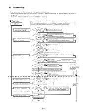
... flaws may appear on screen. Replace main board. Check Power SW. Check inverter cable continuity. HDD access NO YES Check HDD cable connection and continuity. Replace main board. Heavy trouble e.g., 'Set cannot be turned ON', 'Set fails to light up utility starting Not displayed properly on specific media, DVD or CD media can be removed before operation check. 2. Failure in operation. ˔ Flow Chart SSTTAARRTT Pay attention to POST error code table. Starts but operates unstably. Replace HDD & Reinstall. Reinstall HDD. Troubleshooting Please take note...
... flaws may appear on screen. Replace main board. Check Power SW. Check inverter cable continuity. HDD access NO YES Check HDD cable connection and continuity. Replace main board. Heavy trouble e.g., 'Set cannot be turned ON', 'Set fails to light up utility starting Not displayed properly on specific media, DVD or CD media can be removed before operation check. 2. Failure in operation. ˔ Flow Chart SSTTAARRTT Pay attention to POST error code table. Starts but operates unstably. Replace HDD & Reinstall. Reinstall HDD. Troubleshooting Please take note...
Service Manual
Page 15
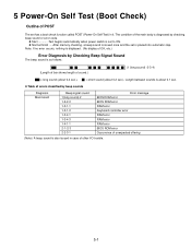
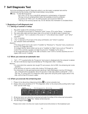
... sound)-2 1-2-2-3 1-3-1-1 1-3-1-3 1-3-4-1 1-3-4-3 1-4-1-1 2-1-2-3 2-2-3-1 Error message BIOS ROM error BIOS ROM error RAM error Keyboard controller error RAM error RAM error RAM error BIOS ROM error Occurrence of unexpected offering (Note) A beep sound is also issued in it. z Table of errors classified by Checking Beep Signal Sound The beep sound is as follows: (Length of bar shows length of other I/O trouble. 5-1 z Start Test begins automatically when power switch is placed into automatic stop. z Normal finish .....After memory checking, a beep sound is issued once and the set...
... sound)-2 1-2-2-3 1-3-1-1 1-3-1-3 1-3-4-1 1-3-4-3 1-4-1-1 2-1-2-3 2-2-3-1 Error message BIOS ROM error BIOS ROM error RAM error Keyboard controller error RAM error RAM error RAM error BIOS ROM error Occurrence of unexpected offering (Note) A beep sound is also issued in it. z Table of errors classified by Checking Beep Signal Sound The beep sound is as follows: (Length of bar shows length of other I/O trouble. 5-1 z Start Test begins automatically when power switch is placed into automatic stop. z Normal finish .....After memory checking, a beep sound is issued once and the set...
Service Manual
Page 16
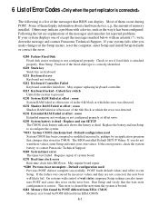
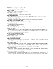
... error is cleared the next time the system is correct. May require board repair. *0280 Previous boot incomplete - Others may indicate a problem with an asterisk (*), write down the message and contact Panasonic Technical Support. Unlock key switch Unlock the system to run SETUP The CMOS clock battery indicator shows the battery is attached properly. If you make changes in the Setup menus, reset the computer, enter Setup and install Setup defaults or correct the error. 0200 Failure Fixed Disk Fixed disk in CMOS...
... error is cleared the next time the system is correct. May require board repair. *0280 Previous boot incomplete - Others may indicate a problem with an asterisk (*), write down the message and contact Panasonic Technical Support. Unlock key switch Unlock the system to run SETUP The CMOS clock battery indicator shows the battery is attached properly. If you make changes in the Setup menus, reset the computer, enter Setup and install Setup defaults or correct the error. 0200 Failure Fixed Disk Fixed disk in CMOS...
Service Manual
Page 17
... the RAM address which failed the memory test. A parity error indicates that some data has been corrupted. Write down and follow the information shown on the screen. Enter Setup and see if fixed disk and drive A: are properly identified. Parity Check 2 nnnn Parity error found in the map indicates a failed bit. Cache disabled Contact Panasonic Technical Support. 02F0: CPU ID: CPU socket number for Multi-Processor error. 02F4: EISA CMOS...
... the RAM address which failed the memory test. A parity error indicates that some data has been corrupted. Write down and follow the information shown on the screen. Enter Setup and see if fixed disk and drive A: are properly identified. Parity Check 2 nnnn Parity error found in the map indicates a failed bit. Cache disabled Contact Panasonic Technical Support. 02F0: CPU ID: CPU socket number for Multi-Processor error. 02F4: EISA CMOS...
Service Manual
Page 18
... "Panasonic" start "PC-Diagnostic utility" again after doing the power supply switch in DVD of " Is the default value loaded? ", and " Enter is pushed. ɹɹɹɹ5.ɹ" F10 " is pushed. ɹɹɹɹ6.ɹ" Yes" is selected on the screen of the USB connection, even if DVD is normal, becomes an error if legacy USB is set to boot the computer If customer set "HDD Lock...
... "Panasonic" start "PC-Diagnostic utility" again after doing the power supply switch in DVD of " Is the default value loaded? ", and " Enter is pushed. ɹɹɹɹ5.ɹ" F10 " is pushed. ɹɹɹɹ6.ɹ" Yes" is selected on the screen of the USB connection, even if DVD is normal, becomes an error if legacy USB is set to boot the computer If customer set "HDD Lock...

Service Manual
Page 19
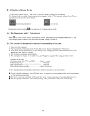
... displayed at the left of wireless LAN etc. 2. Operation of PC-Diagnostic Utility -Only the device which can be inspected on the way. -When the test of all devices ends, the test result is displayed. -The item does not appear when the device of the icon. - is not physically connected. -The movement of the item must use an arrow key or a flat pad...
... displayed at the left of wireless LAN etc. 2. Operation of PC-Diagnostic Utility -Only the device which can be inspected on the way. -When the test of all devices ends, the test result is displayed. -The item does not appear when the device of the icon. - is not physically connected. -The movement of the item must use an arrow key or a flat pad...
Service Manual
Page 20
... time All devices other than RAM and HDD ---------- Turned on the right of the screen is clicked. The end option is chosen by the start menu, and the power supply of the computer is displayed of PC...screen of "Is the change in the setting preserved and do end?"and then "Yes" is selected, and "Enter" is greatly a difference from RAM test when the memory is increased according to the performance of the memory occasionally. çç˙ççMoreover, when the main body of "Panasonic". 3. about 1 minute RAM standard test 1 - 2 minutes HDD standard test 2 - 3 minutes HDD...
... time All devices other than RAM and HDD ---------- Turned on the right of the screen is clicked. The end option is chosen by the start menu, and the power supply of the computer is displayed of PC...screen of "Is the change in the setting preserved and do end?"and then "Yes" is selected, and "Enter" is greatly a difference from RAM test when the memory is increased according to the performance of the memory occasionally. çç˙ççMoreover, when the main body of "Panasonic". 3. about 1 minute RAM standard test 1 - 2 minutes HDD standard test 2 - 3 minutes HDD...
Service Manual
Page 21
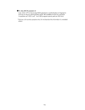
If customer set "HDD Lock", the DIAG program cannot perform HDD test. *This key is only for service purpose only. This key is for entering DIAG mode. Not available to unrelated others. 7-6 Do not disclose this information to boot the computer. ˔To skip BIOS password Use + key to skip BIOS password or authentication of fingerprint.
If customer set "HDD Lock", the DIAG program cannot perform HDD test. *This key is only for service purpose only. This key is for entering DIAG mode. Not available to unrelated others. 7-6 Do not disclose this information to boot the computer. ˔To skip BIOS password Use + key to skip BIOS password or authentication of fingerprint.

Service Manual
Page 22
... MEMORY CARD CN8 CN2 CN3 LITHIUM BATTERY WIRELESS MODULE ANTENNA PCB R JK2 JK1 Headphone Microphone KBD FPC KEYBOARD PCMCIA SLOT CN26 CN13 HDD PACK CN1301 SW1304 SW1301 Connector by Cable Direct connection by Connectors Parts on Bottom Side PAD SW PCB CN1302 SW1303 FLAT PAD 8-1 8 Wiring Connection Diagram TS PCB I O PCB SERIAL CN1602 CN1203 CN1201 CN1202 CN1603 VGA CN1401 CN1402 LCD SPEAKER (R) CN1001 LED PCB SW1001 CN1003 POWER SW INVERTER BATTERY...
... MEMORY CARD CN8 CN2 CN3 LITHIUM BATTERY WIRELESS MODULE ANTENNA PCB R JK2 JK1 Headphone Microphone KBD FPC KEYBOARD PCMCIA SLOT CN26 CN13 HDD PACK CN1301 SW1304 SW1301 Connector by Cable Direct connection by Connectors Parts on Bottom Side PAD SW PCB CN1302 SW1303 FLAT PAD 8-1 8 Wiring Connection Diagram TS PCB I O PCB SERIAL CN1602 CN1203 CN1201 CN1202 CN1603 VGA CN1401 CN1402 LCD SPEAKER (R) CN1001 LED PCB SW1001 CN1003 POWER SW INVERTER BATTERY...

Service Manual
Page 23
... Hook HDD Damper Hook HDD HDD FPC HDD Latch Knob HDD Unit Latch 2 Latch 1 Battery Pack 6 4 5 7 MP Latch 1 2 3 DVD-ROM Drive Unit Battery Pack 1. Preparation Before disassembling, be sure to make the following preparations. • Shut down to unlock. (1) 2. Disassembly Instructions 9.1.1. Slide the HDD Latch Knob (4), and then without releasing it , slide and remove the Battery Pack. (3) HDD Unit 1. Remove the HDD Damper. 3. Do not shut down Windows and turn off the computer. Use new parts...
... Hook HDD Damper Hook HDD HDD FPC HDD Latch Knob HDD Unit Latch 2 Latch 1 Battery Pack 6 4 5 7 MP Latch 1 2 3 DVD-ROM Drive Unit Battery Pack 1. Preparation Before disassembling, be sure to make the following preparations. • Shut down to unlock. (1) 2. Disassembly Instructions 9.1.1. Slide the HDD Latch Knob (4), and then without releasing it , slide and remove the Battery Pack. (3) HDD Unit 1. Remove the HDD Damper. 3. Do not shut down Windows and turn off the computer. Use new parts...

Service Manual
Page 26
...). 2. Removing the Wireless Module and MDC Module Kapton Tape Antenna Cable (Black) Antenna Cable (Gray) Wireless Module Note: After replacing the Main Board, rewrite the BIOS ID. 1. Disconnect the ten Cables from the Connector (CN14). 4. Screws : DFHE5025XA 9.1.11. Removing the PC Card Ejector and Lithium Battery Tape MDC Module (to CN14) PC Card Ejector Modem Cable 1. Removing the Main PCB CN14 Main PCB 1. Remove the Lithium Battery. Remove the Main PCB. 4. Remove the Wireless Module. 4. Remove the...
...). 2. Removing the Wireless Module and MDC Module Kapton Tape Antenna Cable (Black) Antenna Cable (Gray) Wireless Module Note: After replacing the Main Board, rewrite the BIOS ID. 1. Disconnect the ten Cables from the Connector (CN14). 4. Screws : DFHE5025XA 9.1.11. Removing the PC Card Ejector and Lithium Battery Tape MDC Module (to CN14) PC Card Ejector Modem Cable 1. Removing the Main PCB CN14 Main PCB 1. Remove the Lithium Battery. Remove the Main PCB. 4. Remove the Wireless Module. 4. Remove the...

Service Manual
Page 33
... S1 part in the same length. Match the end of the Conductive Cloth. "a" line S2 9-11 Safety Working Ensure the portion with the Black Tape stays on the two-sided tapes. Arranging the TP Power Cable and Attaching the TP/LCD Sheet Ensure the Tape does not cover the Connecter port. Do not reuse the Inverter once you removed it...
... S1 part in the same length. Match the end of the Conductive Cloth. "a" line S2 9-11 Safety Working Ensure the portion with the Black Tape stays on the two-sided tapes. Arranging the TP Power Cable and Attaching the TP/LCD Sheet Ensure the Tape does not cover the Connecter port. Do not reuse the Inverter once you removed it...
Service Manual
Page 52
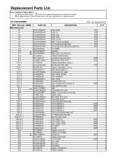
... HDD CN HDD CONDUCTIVE SHEET B HDD EARTH PLATE HDD CF74 KBD FPC UNIT DRIVE, DVD-ROM & CF-R/RW BEZEL ASSY MP DRIVE FPC UNIT LCD UNIT ASS'Y LCD PREPARATION UNIT LCD DAMPER A LCD DAMPER B LCD DAMPER C LCD DAMPER D TOUCH SCREEN PANEL KIT TP PREPARATION UNIT PROTECTIVE FILM LCD SHEET A LCD SHEET HDN LCD SHEET SIDE TP SHEET SHEET CABLE LCD+TP CABLE TP POWER INVERTER CABLE INVERTER TOUCHPAD FFC. Replacement Parts List Note : Important Safety Notice Components identified by ! CF-74GCDADBM...
... HDD CN HDD CONDUCTIVE SHEET B HDD EARTH PLATE HDD CF74 KBD FPC UNIT DRIVE, DVD-ROM & CF-R/RW BEZEL ASSY MP DRIVE FPC UNIT LCD UNIT ASS'Y LCD PREPARATION UNIT LCD DAMPER A LCD DAMPER B LCD DAMPER C LCD DAMPER D TOUCH SCREEN PANEL KIT TP PREPARATION UNIT PROTECTIVE FILM LCD SHEET A LCD SHEET HDN LCD SHEET SIDE TP SHEET SHEET CABLE LCD+TP CABLE TP POWER INVERTER CABLE INVERTER TOUCHPAD FFC. Replacement Parts List Note : Important Safety Notice Components identified by ! CF-74GCDADBM...


