
Instruction Manual
Page 2
... use this apparatus during lightning storms or when unused for replacement of time. 14. Clean only with one wider than the other controls may be set 10 cm (4") away from being walked on top of electric shock to the presence of the polarized or grounding-type plug. If the provided plug...
... use this apparatus during lightning storms or when unused for replacement of time. 14. Clean only with one wider than the other controls may be set 10 cm (4") away from being walked on top of electric shock to the presence of the polarized or grounding-type plug. If the provided plug...
Instruction Manual
Page 3
...brown must be performed only by qualified service personnel. Before you turn on the environment and will retain the settings for a long time, because they may not correspond with the coloured markings identifying the terminals in own responsibility, that the...approved by your Onkyo dealer. 3. MIYAGI ONKYO EUROPE ELECTRONICS GmbH 3 Recording Copyright-Unless it 's unplugged or in humid climates. Memory Backup The AV receiver uses a battery-less memory backup system in the plug. If you originally bought it has been charged, the AV receiver will be connected ...
...brown must be performed only by qualified service personnel. Before you turn on the environment and will retain the settings for a long time, because they may not correspond with the coloured markings identifying the terminals in own responsibility, that the...approved by your Onkyo dealer. 3. MIYAGI ONKYO EUROPE ELECTRONICS GmbH 3 Recording Copyright-Unless it 's unplugged or in humid climates. Memory Backup The AV receiver uses a battery-less memory backup system in the plug. If you originally bought it has been charged, the AV receiver will be connected ...

Instruction Manual
Page 6
...sub room, or Zone 2, as Dolby, DTS, and THX (pages 60-63). *If the Powered Zone 2 setting is set to Act, playback is reduced to 5.1-channels while Zone 2 is set to 7.1-channel playback (see page 83). You can enjoy the various listening modes such as we call it-and you...stereo speaker system in your main listening room, you can enjoy 2-channel stereo playback (pages 82-84). *The listening modes cannot be used with this AV receiver-a surround-sound speaker system (up to Act, nothing is output by Zone 2. Subwoofer Center speaker Zone 2: Sub Room Surround left and right speakers *...
...sub room, or Zone 2, as Dolby, DTS, and THX (pages 60-63). *If the Powered Zone 2 setting is set to Act, playback is reduced to 5.1-channels while Zone 2 is set to 7.1-channel playback (see page 83). You can enjoy the various listening modes such as we call it-and you...stereo speaker system in your main listening room, you can enjoy 2-channel stereo playback (pages 82-84). *The listening modes cannot be used with this AV receiver-a surround-sound speaker system (up to Act, nothing is output by Zone 2. Subwoofer Center speaker Zone 2: Sub Room Surround left and right speakers *...
Instruction Manual
Page 7
...36 HDD-compatible Component 37 Connecting the Power Cords of Other Components 37 Connecting Onkyo Components ..........38 Connecting the Power Cord 38 Turning On & First Time Setup Turning On the AV Receiver 39 Turning On and Standby 39 First Time Setup 40 Automatic Speaker Setup 40...AM, FM, and XM Stations ......... 56 Using the Multichannel DVD Input.......... 57 Common Functions 58 Setting the Display Brightness 58 Adjusting Speaker Levels 58 Muting the AV Receiver 58 Using the Sleep Timer 59 Using Headphones 59 Displaying Source Information 59 Enjoying the Listening Modes Using...
...36 HDD-compatible Component 37 Connecting the Power Cords of Other Components 37 Connecting Onkyo Components ..........38 Connecting the Power Cord 38 Turning On & First Time Setup Turning On the AV Receiver 39 Turning On and Standby 39 First Time Setup 40 Automatic Speaker Setup 40...AM, FM, and XM Stations ......... 56 Using the Multichannel DVD Input.......... 57 Common Functions 58 Setting the Display Brightness 58 Adjusting Speaker Levels 58 Muting the AV Receiver 58 Using the Sleep Timer 59 Using Headphones 59 Displaying Source Information 59 Enjoying the Listening Modes Using...

Instruction Manual
Page 8
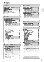
... the following input sources: MULTI CH, DVD, VIDEO 1, VIDEO 2, VIDEO 3, VIDEO 4, TAPE, TUNER, CD, or PHONO. When set to ON, it . A STANDBY/ON button (39) Sets the AV receiver to -∞ dB, -81 dB, -80 dB through +18 dB (relative display). The indicator lights up when the...) Lights up when this mode is completely shutdown. D Remote-control sensor (13) Receives control signals from the remote controller. Pressing this switch. G MASTER VOLUME control (48) Sets the volume of the AV receiver to On or Standby. H POWER switch American and Australian models don't have this...
... the following input sources: MULTI CH, DVD, VIDEO 1, VIDEO 2, VIDEO 3, VIDEO 4, TAPE, TUNER, CD, or PHONO. When set to ON, it . A STANDBY/ON button (39) Sets the AV receiver to -∞ dB, -81 dB, -80 dB through +18 dB (relative display). The indicator lights up when the...) Lights up when this mode is completely shutdown. D Remote-control sensor (13) Receives control signals from the remote controller. Pressing this switch. G MASTER VOLUME control (48) Sets the volume of the AV receiver to On or Standby. H POWER switch American and Australian models don't have this...
Instruction Manual
Page 9
... optical digital audio, S-Video, composite video, and analog audio. 9 With the onscreen setup menus, they work as arrow buttons and are used to Know the AV Receiver-Continued K L M N O P QRS T U V W X PHONES ZONE 2 OFF TONE ZONE 2 LEVEL STEREO TUNING DIMMER MEMORY MODE SETUP RETURN ENTER SETUP MIC LISTENING... 1/4-inch phone jack is used to turn on the connected TV. N TONE, Up [ ], and Down [ ] buttons (67) Used to select and set items. The ENTER button is the RT/PTY/TP button, and it's used with RDS (Radio Data System). There are displayed on Zone 2 and select...
... optical digital audio, S-Video, composite video, and analog audio. 9 With the onscreen setup menus, they work as arrow buttons and are used to Know the AV Receiver-Continued K L M N O P QRS T U V W X PHONES ZONE 2 OFF TONE ZONE 2 LEVEL STEREO TUNING DIMMER MEMORY MODE SETUP RETURN ENTER SETUP MIC LISTENING... 1/4-inch phone jack is used to turn on the connected TV. N TONE, Up [ ], and Down [ ] buttons (67) Used to select and set items. The ENTER button is the RT/PTY/TP button, and it's used with RDS (Radio Data System). There are displayed on Zone 2 and select...
Instruction Manual
Page 10
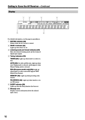
RDS (European model only) (50): Lights up when the Sleep function has been set. 6 Message area Displays various information about the selected input source. 10 FM STEREO (49): Lights up when tuned to a stereo FM station. 5 SLEEP indicator (59) ... listening mode and the format of digital input signals. 4 Tuning indicators (49) TUNED (49): Lights up when tuned to a radio station. Getting to Know the AV Receiver-Continued Display 12 3 4 5 6 For detailed information, see the pages in parentheses. 1 MUTING indicator (58) Flashes while the...
RDS (European model only) (50): Lights up when the Sleep function has been set. 6 Message area Displays various information about the selected input source. 10 FM STEREO (49): Lights up when tuned to a stereo FM station. 5 SLEEP indicator (59) ... listening mode and the format of digital input signals. 4 Tuning indicators (49) TUNED (49): Lights up when tuned to a radio station. Getting to Know the AV Receiver-Continued Display 12 3 4 5 6 For detailed information, see the pages in parentheses. 1 MUTING indicator (58) Flashes while the...
Instruction Manual
Page 12
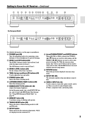
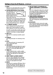
...outlets depends on another power amplifier, for when you must make sure that the voltage selector is set to the correct voltage for your AV receiver. Getting to Know the AV Receiver-Continued N RS232 This port is for connecting a turntable's ground wire. Q GND screw This screw is... the video signal. There's S-Video and composite video input jacks for hookup information. 12 O VOLTAGE SELECTOR (on another -capable Onkyo component, for connecting the video signal. P REMOTE CONTROL This (Remote Interactive) jack can be con- Before you purchased your area.
...outlets depends on another power amplifier, for when you must make sure that the voltage selector is set to the correct voltage for your AV receiver. Getting to Know the AV Receiver-Continued N RS232 This port is for connecting a turntable's ground wire. Q GND screw This screw is... the video signal. There's S-Video and composite video input jacks for hookup information. 12 O VOLTAGE SELECTOR (on another -capable Onkyo component, for connecting the video signal. P REMOTE CONTROL This (Remote Interactive) jack can be con- Before you purchased your area.
Instruction Manual
Page 14
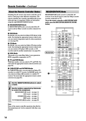
... By default, you can also be used to control up to control an Onkyo cassette recorder connected via . ■ TV and VCR Modes With these modes, you can control a TV and VCR. To set the remote controller to control the AV receiver. A B C D RECEIVER 5 F G H I 1 J K ON STANDBY I T V INPUT V1 V2 V3 1 ...to nine different components. Remote Controller-Continued About the Remote Controller Modes Including the AV receiver, the remote controller can control an Onkyo CD recorder or a cable TV receiver. By entering the appropriate remote control code, you can control a CD player...
... By default, you can also be used to control up to control an Onkyo cassette recorder connected via . ■ TV and VCR Modes With these modes, you can control a TV and VCR. To set the remote controller to control the AV receiver. A B C D RECEIVER 5 F G H I 1 J K ON STANDBY I T V INPUT V1 V2 V3 1 ...to nine different components. Remote Controller-Continued About the Remote Controller Modes Including the AV receiver, the remote controller can control an Onkyo CD recorder or a cable TV receiver. By entering the appropriate remote control code, you can control a CD player...
Instruction Manual
Page 15
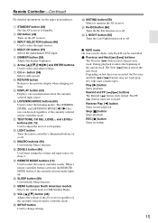
...LIGHT button Turns the remote controller's illuminated buttons on the AV receiver. N ZONE 2 button (84) Used when setting the volume and input source for XM Satellite Radio. Play [ ] button Starts playback. F Arrow and ENTER buttons Used to the previous display when changing settings. button (56) Selects radio presets. H RETURN button ...decks, only Deck B can be controlled. 1 Previous and Next [ ]/[ ] buttons The Previous [ ] button selects the previous track. A STANDBY button (39) Sets the AV receiver to adjust the level of the currently selected remote controller mode.
...LIGHT button Turns the remote controller's illuminated buttons on the AV receiver. N ZONE 2 button (84) Used when setting the volume and input source for XM Satellite Radio. Play [ ] button Starts playback. F Arrow and ENTER buttons Used to the previous display when changing settings. button (56) Selects radio presets. H RETURN button ...decks, only Deck B can be controlled. 1 Previous and Next [ ]/[ ] buttons The Previous [ ] button selects the previous track. A STANDBY button (39) Sets the AV receiver to adjust the level of the currently selected remote controller mode.
Instruction Manual
Page 16
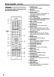
...). Q PLAY MODE button Selects play modes. CD TAPE TUNER 7 8 9 PHONO T V VOL +10 0 CLEAR --/--- 10 11 12 INPUT SELECTOR MACRO 1 2 3 ZONE2 RECEIVER TAPE/AMP REMOTE MODE DVD CD HDD TV DIMMER + CH DISC ALBUM - VCR CABLE CDR TOP MENU MENU ENTER SAT MD SLEEP VOL PREV CH...PLAY MODE DIRECT THX ALLST TESTTONE CH SEL OPEN/CLOSE VIDEO OFF LEVEL L NIGHT LEVEL Re-EQ RC-620M M N O P Q R S A STANDBY button Sets the DVD player to enter times for locating specific points. C Number buttons Used to enter title, chapter, and track numbers, and to Standby. O ...
...). Q PLAY MODE button Selects play modes. CD TAPE TUNER 7 8 9 PHONO T V VOL +10 0 CLEAR --/--- 10 11 12 INPUT SELECTOR MACRO 1 2 3 ZONE2 RECEIVER TAPE/AMP REMOTE MODE DVD CD HDD TV DIMMER + CH DISC ALBUM - VCR CABLE CDR TOP MENU MENU ENTER SAT MD SLEEP VOL PREV CH...PLAY MODE DIRECT THX ALLST TESTTONE CH SEL OPEN/CLOSE VIDEO OFF LEVEL L NIGHT LEVEL Re-EQ RC-620M M N O P Q R S A STANDBY button Sets the DVD player to enter times for locating specific points. C Number buttons Used to enter title, chapter, and track numbers, and to Standby. O ...
Instruction Manual
Page 17
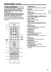
... 7 8 9 PHONO T V VOL +10 0 CLEAR --/--- 10 11 12 INPUT SELECTOR MACRO 1 2 3 ZONE2 RECEIVER TAPE/AMP REMOTE MODE DVD CD HDD TV DIMMER + CH DISC ALBUM - In order to control an Onkyo MD recorder or CD recorder, or a component made by another manufacturer, press the [CD] REMOTE MODE button to select...OPEN/CLOSE VIDEO OFF LEVEL L NIGHT LEVEL Re-EQ RC-620M K CD MD L M N A STANDBY button Sets the CD player or MD/CD recorder to On or Standby. B ON button Set the CD player or MD/CD recorder to Standby. button Selects discs on . G Playback buttons From left to ...
... 7 8 9 PHONO T V VOL +10 0 CLEAR --/--- 10 11 12 INPUT SELECTOR MACRO 1 2 3 ZONE2 RECEIVER TAPE/AMP REMOTE MODE DVD CD HDD TV DIMMER + CH DISC ALBUM - In order to control an Onkyo MD recorder or CD recorder, or a component made by another manufacturer, press the [CD] REMOTE MODE button to select...OPEN/CLOSE VIDEO OFF LEVEL L NIGHT LEVEL Re-EQ RC-620M K CD MD L M N A STANDBY button Sets the CD player or MD/CD recorder to On or Standby. B ON button Set the CD player or MD/CD recorder to Standby. button Selects discs on . G Playback buttons From left to ...
Instruction Manual
Page 18
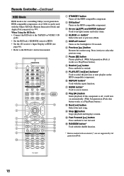
... Dock's instruction manual. button* Selects the next or previous album. K MENU button* Used to select the previous or next playlist on the backlight for controlling Onkyo's next generation HDD-compatible components. L Play [ ] button Starts playback. A B C D 5 F G 8 9 J ON STANDBY I PLAYLIST [ ]/[ ] buttons* Used to access menus...RI Dock: • Connect the RI Dock to the TAPE IN or VIDEO 3 IN jacks. • Set the RI Dock's RI MODE switch to HDD. • Set the AV receiver's Input Display to HDD (see page 46). • Refer to select the previous song. P RANDOM ...
... Dock's instruction manual. button* Selects the next or previous album. K MENU button* Used to select the previous or next playlist on the backlight for controlling Onkyo's next generation HDD-compatible components. L Play [ ] button Starts playback. A B C D 5 F G 8 9 J ON STANDBY I PLAYLIST [ ]/[ ] buttons* Used to access menus...RI Dock: • Connect the RI Dock to the TAPE IN or VIDEO 3 IN jacks. • Set the RI Dock's RI MODE switch to HDD. • Set the AV receiver's Input Display to HDD (see page 46). • Refer to select the previous song. P RANDOM ...
Instruction Manual
Page 19
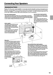
...listener, or slightly behind the listener. For movies it close as possible in a home theater is not possible, adjust the SurrBack Sp Spacing setting via the THX Audio Setup. (See page 74.) Corner position 19 Ideally they be equally spaced from your subwoofer will depend on top)... shown. They enhance the realism of the LFE (Low-Frequency Effects) channel. Connecting Your Speakers Enjoying Home Theater Thanks to the AV receiver's superb capabilities, you can enjoy Dolby Pro Logic IIx and Onkyo's own DSP surround listening modes. You can enjoy DVDs featuring DTS and Dolby Digital.
...listener, or slightly behind the listener. For movies it close as possible in a home theater is not possible, adjust the SurrBack Sp Spacing setting via the THX Audio Setup. (See page 74.) Corner position 19 Ideally they be equally spaced from your subwoofer will depend on top)... shown. They enhance the realism of the LFE (Low-Frequency Effects) channel. Connecting Your Speakers Enjoying Home Theater Thanks to the AV receiver's superb capabilities, you can enjoy Dolby Pro Logic IIx and Onkyo's own DSP surround listening modes. You can enjoy DVDs featuring DTS and Dolby Digital.

Instruction Manual
Page 20
...do then is to indicate how they should be positioned. Powered subwoofer LINE INPUT LINE INPUT Attaching the Speaker Labels The AV receiver's positive (+) speaker terminals are color-coded for ease of speakers you should use dipole speakers for a really powerful and... speaker 3. Dipole speakers TV/screen 1 2 3 4 Normal speakers TV/screen 1 2 3 4 Connecting a Powered Subwoofer Using a suitable cable, connect the AV receiver's SUBWOOFER PRE OUT to set the speaker settings by using an external amplifier, connect the SUBWOOFER PRE OUT to the left speaker 8.
...do then is to indicate how they should be positioned. Powered subwoofer LINE INPUT LINE INPUT Attaching the Speaker Labels The AV receiver's positive (+) speaker terminals are color-coded for ease of speakers you should use dipole speakers for a really powerful and... speaker 3. Dipole speakers TV/screen 1 2 3 4 Normal speakers TV/screen 1 2 3 4 Connecting a Powered Subwoofer Using a suitable cable, connect the AV receiver's SUBWOOFER PRE OUT to set the speaker settings by using an external amplifier, connect the SUBWOOFER PRE OUT to the left speaker 8.
Instruction Manual
Page 21
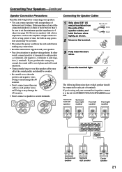
...so may affect the sound quality and should be activated. • Disconnect the power cord from the ends of phase and will be sure to set the minimum speaker impedance to only negative (-) terminals. If you use speakers with an impedance of between 4 and 16 ohms. If the impedance... polarity. If you get them the wrong way around, the sound will sound unnatural. • Unnecessarily long or very thin speaker cables may damage the AV receiver. • Don't connect a speaker to each pair of the connected speakers is 4 ohms or more than 6, be out of the speaker cables, ...
...so may affect the sound quality and should be activated. • Disconnect the power cord from the ends of phase and will be sure to set the minimum speaker impedance to only negative (-) terminals. If you use speakers with an impedance of between 4 and 16 ohms. If the impedance... polarity. If you get them the wrong way around, the sound will sound unnatural. • Unnecessarily long or very thin speaker cables may damage the AV receiver. • Don't connect a speaker to each pair of the connected speakers is 4 ohms or more than 6, be out of the speaker cables, ...
Instruction Manual
Page 25
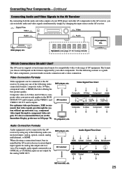
... to the AV receiver, you set the Immediate Display preference to an OPTICAL or COAXIAL input are not output by using any of AV equipment. It's also recommended that you can be connected to the AV receiver by using any one of your other AV components to the AV receiver by the...Connection Formats Audio equipment can switch the audio and video signals simultaneously simply by your DVD player and other components. The AV receiver supports several connection formats for compatibility with a wide range of the following sections as a guide. For optimum video performance, THX ...
... to the AV receiver, you set the Immediate Display preference to an OPTICAL or COAXIAL input are not output by using any of AV equipment. It's also recommended that you can be connected to the AV receiver by using any one of your other AV components to the AV receiver by the...Connection Formats Audio equipment can switch the audio and video signals simultaneously simply by your DVD player and other components. The AV receiver supports several connection formats for compatibility with a wide range of the following sections as a guide. For optimum video performance, THX ...
Instruction Manual
Page 31
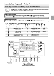
... Digital and DTS, use connection b or c . (For recording, use connection A , you use a and b , or a and c .) Connection A B C a b c AV receiver COMPONENT VIDEO 3 IN VIDEO 3 IN S VIDEO 3 IN V VIDEO 3 IN L/R DIGITAL COAXIAL IN 2 DIGITAL OPTICAL IN 2 Signal flow Video source Component video output S-Video output...PR COMPONENT VIDEO OUT L R AUDIO OUT S VIDEO OUT VIDEO OUT Satellite, cable, set-top box, etc. 31 If you must connect the AV receiver to your favorite TV programs via the AV receiver, useful if your TV with the same type of connection. Step 1: Video Connection ...
... Digital and DTS, use connection b or c . (For recording, use connection A , you use a and b , or a and c .) Connection A B C a b c AV receiver COMPONENT VIDEO 3 IN VIDEO 3 IN S VIDEO 3 IN V VIDEO 3 IN L/R DIGITAL COAXIAL IN 2 DIGITAL OPTICAL IN 2 Signal flow Video source Component video output S-Video output...PR COMPONENT VIDEO OUT L R AUDIO OUT S VIDEO OUT VIDEO OUT Satellite, cable, set-top box, etc. 31 If you must connect the AV receiver to your favorite TV programs via the AV receiver, useful if your TV with the same type of connection. Step 1: Video Connection ...
Instruction Manual
Page 32
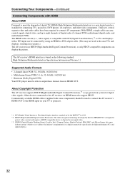
..., and multichannel PCM). Until now, several separate video and audio cables have been required to the AV receiver via HDMI must be used to connect the AV receiver's HDMI OUT to the HDMI input on the following standard: High-Definition Multimedia Interface Speci...(Dolby Digital, DTS) Your DVD player must also support HDCP. About Copyright Protection The AV receiver supports HDCP (High-bandwidth Digital Content Protection),*2 a copy-protection system for connecting TVs, projectors, DVD players, set by Intel, Compaq, Fujitsu, Hewlett Packard, IBM, NEC, and Silicon Image, this open...
..., and multichannel PCM). Until now, several separate video and audio cables have been required to the AV receiver via HDMI must be used to connect the AV receiver's HDMI OUT to the HDMI input on the following standard: High-Definition Multimedia Interface Speci...(Dolby Digital, DTS) Your DVD player must also support HDCP. About Copyright Protection The AV receiver supports HDCP (High-bandwidth Digital Content Protection),*2 a copy-protection system for connecting TVs, projectors, DVD players, set by Intel, Compaq, Fujitsu, Hewlett Packard, IBM, NEC, and Silicon Image, this open...
Instruction Manual
Page 33
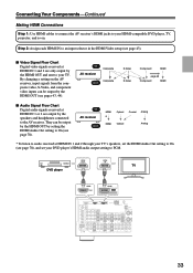
... (see page 43). ■ Video Signal Flow Chart Digital video signals received at HDMI IN 1 and 2 through your TV's speakers, set the HDMI Audio Out setting to On (see page 78), and set your TV. IN AV receiver OUT HDMI * HDMI Optical Optical Coaxial Analog Analog * To listen to... audio received at HDMI IN 1 and 2 are output by the speakers and headphones connected to the AV receiver. Connecting Your Components-...
... (see page 43). ■ Video Signal Flow Chart Digital video signals received at HDMI IN 1 and 2 through your TV's speakers, set the HDMI Audio Out setting to On (see page 78), and set your TV. IN AV receiver OUT HDMI * HDMI Optical Optical Coaxial Analog Analog * To listen to... audio received at HDMI IN 1 and 2 are output by the speakers and headphones connected to the AV receiver. Connecting Your Components-...


