Owner Manual
Page 4
... by the remote controller signals (IR IN) (TX-SR700/ 700E only 22 If the remote controller signal does not reach the TXSR700/700E remote sensor 22 Connecting the remote zone (Zone 2) speakers (TX-SR700/700E only 23 When using the ZONE 2 SPEAKERS terminals 23 When using the ZONE 2 PRE OUT... terminals 23 AC OUTLETS 29 REMOTE CONTROL 29 Connections (TX-SR600/600E 24 Connecting your audio components 24 Connecting your video...
... by the remote controller signals (IR IN) (TX-SR700/ 700E only 22 If the remote controller signal does not reach the TXSR700/700E remote sensor 22 Connecting the remote zone (Zone 2) speakers (TX-SR700/700E only 23 When using the ZONE 2 SPEAKERS terminals 23 When using the ZONE 2 PRE OUT... terminals 23 AC OUTLETS 29 REMOTE CONTROL 29 Connections (TX-SR600/600E 24 Connecting your audio components 24 Connecting your video...
Owner Manual
Page 5
...controller 63 Overview 63 Calling up a preset radio station 63 Controlling an Onkyo cassette tape deck 63 Controlling an Onkyo CD player 64 Controlling an Onkyo DVD player 65 Controlling an Onkyo MD recorder 66 VCR and TV MODE buttons 66 Entering a pre-...of the messages shown below appears 78 Specifications (TX-SR700/700E 79 Specifications (TX-SR600/600E) ....... GERMERING, GERMANY I. Contents Selecting an Audio Component 44 Basic operation (TX-SR700/700E 44 Basic operation (TX-SR600/600E 45 Selecting speakers (SPEAKERS A, B) (TX-SR600/600E only 45 Selecting the type of...
...controller 63 Overview 63 Calling up a preset radio station 63 Controlling an Onkyo cassette tape deck 63 Controlling an Onkyo CD player 64 Controlling an Onkyo DVD player 65 Controlling an Onkyo MD recorder 66 VCR and TV MODE buttons 66 Entering a pre-...of the messages shown below appears 78 Specifications (TX-SR700/700E 79 Specifications (TX-SR600/600E) ....... GERMERING, GERMANY I. Contents Selecting an Audio Component 44 Basic operation (TX-SR700/700E 44 Basic operation (TX-SR600/600E 45 Selecting speakers (SPEAKERS A, B) (TX-SR600/600E only 45 Selecting the type of...
Owner Manual
Page 6
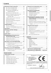
Features TX-SR700/700E Amplifier Features I 100 W × 2 (Front)/ 100 W (Center)/ 100 W × 2... Dolby Pro Logic II I DTS, DTS-ES Extended Surround, DTS Neo:6 I Non-Scaling Configuration I CinemaFILTER I "Easy-set" speaker configuration I Crossover Adjustment (80/100/120 Hz) I Onscreen graphical displays I Optical Digital Output I 2 component video inputs and ... S-Video, Optical inputs I Multi channel input for DVD-Audio I Pre-out terminal for Subwoofer I Color-coded speaker terminals I A/B speaker drive FM/AM Tuner Features I 40 FM/AM random presets I FM auto tuning I RDS (European models) ...
Features TX-SR700/700E Amplifier Features I 100 W × 2 (Front)/ 100 W (Center)/ 100 W × 2... Dolby Pro Logic II I DTS, DTS-ES Extended Surround, DTS Neo:6 I Non-Scaling Configuration I CinemaFILTER I "Easy-set" speaker configuration I Crossover Adjustment (80/100/120 Hz) I Onscreen graphical displays I Optical Digital Output I 2 component video inputs and ... S-Video, Optical inputs I Multi channel input for DVD-Audio I Pre-out terminal for Subwoofer I Color-coded speaker terminals I A/B speaker drive FM/AM Tuner Features I 40 FM/AM random presets I FM auto tuning I RDS (European models) ...
Owner Manual
Page 7
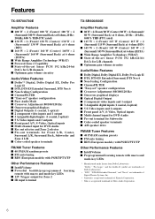
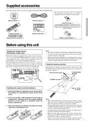
... WOOFER SELECTOR R FRONT SURROUND CENTER L ZONE 2 L SURROUND BACK SPEAKER PRE OUT R R AV RECEIVER 120 V MODEL NO. If the remote controller does not operate smoothly, remove the old batteries and replace them both with the TX-SR700/700E/600/600E. The STANDBY indicator lights up when the unit receives...battery compartment cover by pressing it and sliding it was purchased.) 75/300 Ω antenna adapter × 1 Before using the TX-SR700/700E/600/600E near equipment that uses infrared rays may prevent proper remote controller operation. • If there is appropriate. Its ...
... WOOFER SELECTOR R FRONT SURROUND CENTER L ZONE 2 L SURROUND BACK SPEAKER PRE OUT R R AV RECEIVER 120 V MODEL NO. If the remote controller does not operate smoothly, remove the old batteries and replace them both with the TX-SR700/700E/600/600E. The STANDBY indicator lights up when the unit receives...battery compartment cover by pressing it and sliding it was purchased.) 75/300 Ω antenna adapter × 1 Before using the TX-SR700/700E/600/600E near equipment that uses infrared rays may prevent proper remote controller operation. • If there is appropriate. Its ...
Owner Manual
Page 10
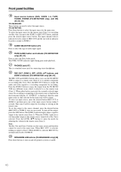
... OUT button to output the audio and video signals to the remote zone (Zone 2). To turn on and off speakers systems A and B. 10 Note: The Rec Out and Zone 2 buttons use the TX-SR700/ 700E to output to a remote zone (Zone 2) or to SOURCE. When ZONE 2 is selected, REC OUT is a .... PHONES jack [47] This is automatically fixed to another component for connecting stereo headphones. REC OUT, ZONE 2, OFF, LEVEL / buttons, and ZONE 2 indicator (TX-SR700/700E only) [60, 61] The REC OUT and ZONE 2 buttons allow you to use the same circuit and therefore cannot be output for recording or...
... OUT button to output the audio and video signals to the remote zone (Zone 2). To turn on and off speakers systems A and B. 10 Note: The Rec Out and Zone 2 buttons use the TX-SR700/ 700E to output to a remote zone (Zone 2) or to SOURCE. When ZONE 2 is selected, REC OUT is a .... PHONES jack [47] This is automatically fixed to another component for connecting stereo headphones. REC OUT, ZONE 2, OFF, LEVEL / buttons, and ZONE 2 indicator (TX-SR700/700E only) [60, 61] The REC OUT and ZONE 2 buttons allow you to use the same circuit and therefore cannot be output for recording or...
Owner Manual
Page 11
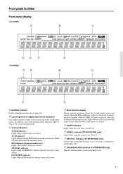
... and volume. REC OUT indicator (TX-SR700/700E only) Lights when recording the input source from one of the current input source. Turns off when placed into the monaural mode. Tuning indicators TUNED indicator Lights when a radio station is turned on . SPEAKERS A/B indicators (TX-SR600/600E only) Indicates which speaker system is received in use...) Lights when an RDS station is selected. However, does not show the format of the listening mode indicators lights to another (Rec Out). ZONE 2 indicator (TX-SR700/700E only) Lights when using the remote zone (Zone 2).
... and volume. REC OUT indicator (TX-SR700/700E only) Lights when recording the input source from one of the current input source. Turns off when placed into the monaural mode. Tuning indicators TUNED indicator Lights when a radio station is turned on . SPEAKERS A/B indicators (TX-SR600/600E only) Indicates which speaker system is received in use...) Lights when an RDS station is selected. However, does not show the format of the listening mode indicators lights to another (Rec Out). ZONE 2 indicator (TX-SR700/700E only) Lights when using the remote zone (Zone 2).
Owner Manual
Page 12
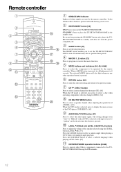
...changers (DISC). [64] CH SEL/TOP MENU button Press to select a speaker channel when adjusting the speaker level (CH SEL). [39] When the DVD mode is pressed, it will also light whenever any other Onkyo components connected to select the audio input signal. Be aware that pressing the STANDBY...select a preset channel for 8 seconds. ON/STANDBY button [33] ON: Press to set the TX-SR700/700E/600/ 600E to place the TX-SR700/700E/600/600E in standby and does not turn on the TX-SR700/700E/600/600E. SLEEP button [47] Press to turn the power completely off automatically after a ...
...changers (DISC). [64] CH SEL/TOP MENU button Press to select a speaker channel when adjusting the speaker level (CH SEL). [39] When the DVD mode is pressed, it will also light whenever any other Onkyo components connected to select the audio input signal. Be aware that pressing the STANDBY...select a preset channel for 8 seconds. ON/STANDBY button [33] ON: Press to set the TX-SR700/700E/600/ 600E to place the TX-SR700/700E/600/600E in standby and does not turn on the TX-SR700/700E/600/600E. SLEEP button [47] Press to turn the power completely off automatically after a ...
Owner Manual
Page 13
TX-SR700/700E: Not used with the TX-SR700/700E. Use this button in conjunction with the LEVEL / and CH SEL buttons to calibrate the speakers levels without entering the Setup Menu. [39] When the DVD mode is selected, press to find the specific section on a DVD where you can ...] 13 TEST/MENU button This button is given here. Numeric key/Listening mode, SP A, SP B, CINE FLTR, DISPLAY, DIMMER buttons 1 to set the speaker output levels. TX-SR700/700E: Press to select the Pure Audio mode. [51] DIRECT, STEREO, SURR, ALL ST, DSP: You can turn the CinemaFILTER function on or off...
TX-SR700/700E: Not used with the TX-SR700/700E. Use this button in conjunction with the LEVEL / and CH SEL buttons to calibrate the speakers levels without entering the Setup Menu. [39] When the DVD mode is selected, press to find the specific section on a DVD where you can ...] 13 TEST/MENU button This button is given here. Numeric key/Listening mode, SP A, SP B, CINE FLTR, DISPLAY, DIMMER buttons 1 to set the speaker output levels. TX-SR700/700E: Press to select the Pure Audio mode. [51] DIRECT, STEREO, SURR, ALL ST, DSP: You can turn the CinemaFILTER function on or off...

Owner Manual
Page 14
... all plugs and connectors securely. Before you connect a cable to the equipment. Optical digital terminals The optical digital terminals are provided with power cords and speaker cables. Connections • Be sure to always refer to the instructions that came with the component that you are connecting. • Do not plug in...
... all plugs and connectors securely. Before you connect a cable to the equipment. Optical digital terminals The optical digital terminals are provided with power cords and speaker cables. Connections • Be sure to always refer to the instructions that came with the component that you are connecting. • Do not plug in...
Owner Manual
Page 15
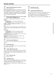
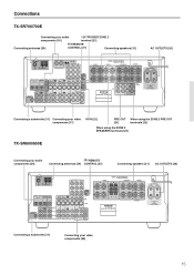
... L R TAPE OUT IN S VIDEO IN IN OUT IN FRONT SURR CENTER L L R VIDEO 3 VIDEO 2 VIDEO 1 R DVD SUB WOOFER FRONT SPEAKERS A 27122965 CAUTION: SPEAKER IMPEDANCE 6 OHMS MIN. /SPEAKER SURROUND SPEAKERS B L L R R CENTER SPEAKER SURROUND BACK SPEAKER AV RECEIVER MODEL NO. Connections TX-SR700/700E Connecting your audio components [16] 12V TRIGGER ZONE 2 terminal [21] Connecting antennas [34] REMOTE CONTROL [27] Connecting...
... L R TAPE OUT IN S VIDEO IN IN OUT IN FRONT SURR CENTER L L R VIDEO 3 VIDEO 2 VIDEO 1 R DVD SUB WOOFER FRONT SPEAKERS A 27122965 CAUTION: SPEAKER IMPEDANCE 6 OHMS MIN. /SPEAKER SURROUND SPEAKERS B L L R R CENTER SPEAKER SURROUND BACK SPEAKER AV RECEIVER MODEL NO. Connections TX-SR700/700E Connecting your audio components [16] 12V TRIGGER ZONE 2 terminal [21] Connecting antennas [34] REMOTE CONTROL [27] Connecting...
Owner Manual
Page 21
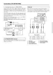
...SPEAKERS 27122974 CAUTION: SPEAKER IMPEDANCE 6 OHMS MIN. /SPEAKER ZONE 2 SPEAKERS SURROUND SPEAKERS L CENTER SPEAKER R FRONT SURROUND CENTER L ZONE 2 L SURROUND BACK SPEAKER PRE OUT R R AV RECEIVER MODEL NO. Subwoofer 2. Center speaker 21 Or if the device has an S video output jack, connect it to the VIDEO 4 DIGITAL jack of the TX-SR700... Front Surround Power amplifier 12V TRIGGER ZONE 2 terminal When the TX-SR700/700E is fixed to the VIDEO 4 S VIDEO jack of the TX-SR700/700E. Surround right speaker 5. Make sure that you can use an auxiliary power amplifiers ...
...SPEAKERS 27122974 CAUTION: SPEAKER IMPEDANCE 6 OHMS MIN. /SPEAKER ZONE 2 SPEAKERS SURROUND SPEAKERS L CENTER SPEAKER R FRONT SURROUND CENTER L ZONE 2 L SURROUND BACK SPEAKER PRE OUT R R AV RECEIVER MODEL NO. Subwoofer 2. Center speaker 21 Or if the device has an S video output jack, connect it to the VIDEO 4 DIGITAL jack of the TX-SR700... Front Surround Power amplifier 12V TRIGGER ZONE 2 terminal When the TX-SR700/700E is fixed to the VIDEO 4 S VIDEO jack of the TX-SR700/700E. Surround right speaker 5. Make sure that you can use an auxiliary power amplifiers ...
Owner Manual
Page 23
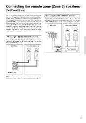
...two different rooms so that two or more people can connect the speakers for the remote zone (Zone 2) to make the proper connections for the remote zone. The room where the TX-SR700/700E is actually located is referred to as the remote zone (...Remote Zone (Zone 2) TX-SR700/700E FRONT SURROUND CENTER ZONE 2 L L PRE OUT R R SURROUND BACK Zone 2 Left speaker Zone 2 Right speaker Left (white) Right (red) Power amplifier ZONE 2 SPEAKERS L R TX-SR700/700E Note: It is physically separated. Connecting the remote zone (Zone 2) speakers (TX-SR700/700E only) The TX-SR700/700E allows you to...
...two different rooms so that two or more people can connect the speakers for the remote zone (Zone 2) to make the proper connections for the remote zone. The room where the TX-SR700/700E is actually located is referred to as the remote zone (...Remote Zone (Zone 2) TX-SR700/700E FRONT SURROUND CENTER ZONE 2 L L PRE OUT R R SURROUND BACK Zone 2 Left speaker Zone 2 Right speaker Left (white) Right (red) Power amplifier ZONE 2 SPEAKERS L R TX-SR700/700E Note: It is physically separated. Connecting the remote zone (Zone 2) speakers (TX-SR700/700E only) The TX-SR700/700E allows you to...
Owner Manual
Page 30
... is aimed at the location of the listener's ears when at the listening position. • Place front left speaker 7 Surround right speaker 8 Surround back speaker 9 Listening position Using the speaker labels The positive speaker terminals on the TX-SR700/700E/600/600E are both very important. Improves the quality of the listener's ears. Here, only typical examples...
... is aimed at the location of the listener's ears when at the listening position. • Place front left speaker 7 Surround right speaker 8 Surround back speaker 9 Listening position Using the speaker labels The positive speaker terminals on the TX-SR700/700E/600/600E are both very important. Improves the quality of the listener's ears. Here, only typical examples...

Owner Manual
Page 31
... a subwoofer with an impedance between 6 and 16 Ω to your TX-SR700/ 700E/600/600E. Screw down the speaker terminal cap. 31 Connecting speakers Connecting speakers After determining the layout of your speaker system, it is now necessary to connect the speakers correctly to the TX-SR700/700E/600/600E. SPEAKER B (TX-SR600/600E only) 1. Strip away approx. 5/8 inch (15 mm...
... a subwoofer with an impedance between 6 and 16 Ω to your TX-SR700/ 700E/600/600E. Screw down the speaker terminal cap. 31 Connecting speakers Connecting speakers After determining the layout of your speaker system, it is now necessary to connect the speakers correctly to the TX-SR700/700E/600/600E. SPEAKER B (TX-SR600/600E only) 1. Strip away approx. 5/8 inch (15 mm...

Owner Manual
Page 32
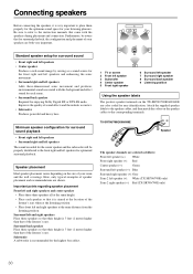
... OUTLETS AC 230-240V 50 Hz SWITCHED TOTAL 100W MAX. Connecting speakers TX-SR700/700E Front right speaker Center speaker Front left B speaker B speaker 32 Subwoofer Surround right speaker SPEAKERS B Surround back speaker Surround left speaker Front right Front left speaker ANTENNA FM AM 75 GND R L PHONO IN COMPONENT VIDEO INPUT 2 INPUT 1 OUTPUT Y L PB DIGITAL INPUT OPTICAL 2 1 DIGITAL VIDEO 3 OUTPUT COAXIAL IN...
... OUTLETS AC 230-240V 50 Hz SWITCHED TOTAL 100W MAX. Connecting speakers TX-SR700/700E Front right speaker Center speaker Front left B speaker B speaker 32 Subwoofer Surround right speaker SPEAKERS B Surround back speaker Surround left speaker Front right Front left speaker ANTENNA FM AM 75 GND R L PHONO IN COMPONENT VIDEO INPUT 2 INPUT 1 OUTPUT Y L PB DIGITAL INPUT OPTICAL 2 1 DIGITAL VIDEO 3 OUTPUT COAXIAL IN...
Owner Manual
Page 33
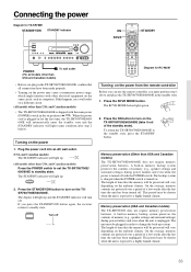
... switch. On the average, memory contents are protected over a period of memory (e.g., speaker settings and surround settings) during power failures and even when the unit is exposed to standby state. Connecting the power Diagram for the first time, the TX-SR700/700E/600/ 600E will automatically enter the standby state and the STANDBY...
... switch. On the average, memory contents are protected over a period of memory (e.g., speaker settings and surround settings) during power failures and even when the unit is exposed to standby state. Connecting the power Diagram for the first time, the TX-SR700/700E/600/ 600E will automatically enter the standby state and the STANDBY...
Owner Manual
Page 34
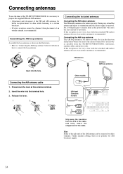
...VIDEO 2 OUTPUT COAXIAL IN OUT IN OU OPTICAL 2 1 OPTICAL COAXIAL DIGITAL INPUT IN OUT IN IN OUT IN OU Strip away the insulation from the TX-SR700/700E/600/600E, televisions, speaker cables, and power cords. Hint: Either of the split ends of the cable. Connecting antennas To use the tuner of the... TX-SR700/700E/600/600E, it is necessary to prepare the supplied FM and AM antennas. • Adjustment and placement of the FM and AM ...
...VIDEO 2 OUTPUT COAXIAL IN OUT IN OU OPTICAL 2 1 OPTICAL COAXIAL DIGITAL INPUT IN OUT IN IN OUT IN OU Strip away the insulation from the TX-SR700/700E/600/600E, televisions, speaker cables, and power cords. Hint: Either of the split ends of the cable. Connecting antennas To use the tuner of the... TX-SR700/700E/600/600E, it is necessary to prepare the supplied FM and AM antennas. • Adjustment and placement of the FM and AM ...
Owner Manual
Page 36
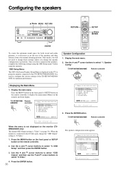
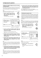
...or SETUP button on the remote controller to select "S Video." 4. TX-SR700/700E/ Remote 600/600E controller * Menu 1.Speaker Config 2.Speaker Distance 3.Level Calibration 4.Input Setup 5.OSD Setup 6.Preference |ENTER|Quit:|SETUP| * Menu 1.Speaker Config 2.Speaker Distance 3.Level Calibration 4.Input Setup 5.OSD Setup 6.Preference |ENTER|... to display the main menu (Menu) on the TV or projector monitor connected to the TX-SR700/700E/600/600E. Speaker Config." Display the main menu. TX-SR700/700E/600/600E Remote controller When the menu is not displayed on the remote controller. 2....
...or SETUP button on the remote controller to select "S Video." 4. TX-SR700/700E/ Remote 600/600E controller * Menu 1.Speaker Config 2.Speaker Distance 3.Level Calibration 4.Input Setup 5.OSD Setup 6.Preference |ENTER|Quit:|SETUP| * Menu 1.Speaker Config 2.Speaker Distance 3.Level Calibration 4.Input Setup 5.OSD Setup 6.Preference |ENTER|... to display the main menu (Menu) on the TV or projector monitor connected to the TX-SR700/700E/600/600E. Speaker Config." Display the main menu. TX-SR700/700E/600/600E Remote controller When the menu is not displayed on the remote controller. 2....

Owner Manual
Page 37
...Hz. Small: Select if the surround back speaker is small sized. • If "None" is selected for the Surround setting, this setting will not appear. • If "Small" is connected. Yes: Select when a subwoofer is large sized. TX-SR700/700E/600/600E Remote controller 9. None: Select... if no surround left and right speakers are cut from speakers set to "Small" and sent to the subwoofer (or to speakers set to select the surround back speaker setting. The crossover frequency is selected ...
...Hz. Small: Select if the surround back speaker is small sized. • If "None" is selected for the Surround setting, this setting will not appear. • If "Small" is connected. Yes: Select when a subwoofer is large sized. TX-SR700/700E/600/600E Remote controller 9. None: Select... if no surround left and right speakers are cut from speakers set to "Small" and sent to the subwoofer (or to speakers set to select the surround back speaker setting. The crossover frequency is selected ...
Owner Manual
Page 38
.... These settings and the distance settings performed in 1-foot (0.3 meter) increments. Select the setting closest to the actual distance from the surround back speakers to your normal listening position. Use the and cursor buttons to select "Front L/R" and then use the CH SEL, LEVEL , and LEVEL buttons... menu and then press the ENTER button. Level Calibration" on the remote controller button to set the distance from the front left and right speakers are at the same level. Use the and cursor buttons to select "3. For example, if 30 feet (9 meters) is especially important for...
.... These settings and the distance settings performed in 1-foot (0.3 meter) increments. Select the setting closest to the actual distance from the surround back speakers to your normal listening position. Use the and cursor buttons to select "Front L/R" and then use the CH SEL, LEVEL , and LEVEL buttons... menu and then press the ENTER button. Level Calibration" on the remote controller button to set the distance from the front left and right speakers are at the same level. Use the and cursor buttons to select "3. For example, if 30 feet (9 meters) is especially important for...

