
Uk Manual
Page 12
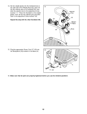
...selector pins and slide them to the adjustment holes marked "1.1". Repeat this step with the other Dumbbell (44). 44 42 Selector Pins 44 Weight Plates Slots 15. Next, lift 14 the two selector pins on a Dumbbell (44), and slide the selector pins to the adjustment holes marked "6.8".... Set ten weight plates into the Receptacle (18) located on the weight plates. Plug the appropriate Power Cord (17, 60) into the indicated slots in the right side of the Weight Rest (42). Make sure...
...selector pins and slide them to the adjustment holes marked "1.1". Repeat this step with the other Dumbbell (44). 44 42 Selector Pins 44 Weight Plates Slots 15. Next, lift 14 the two selector pins on a Dumbbell (44), and slide the selector pins to the adjustment holes marked "6.8".... Set ten weight plates into the Receptacle (18) located on the weight plates. Plug the appropriate Power Cord (17, 60) into the indicated slots in the right side of the Weight Rest (42). Make sure...
Uk Manual
Page 13
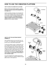
...surface. each dumbbell handle. Adjust the other selector pin on the weight rest as shown. To use extreme caution while moving the vibration platform, unplug the power cord and remove the dumbbells from side to side to one of the adjustment holes, and then release the selector pin. Always... attach the same number of weight plates to the desired location. Do not move the vibration platform to both sides of each dumbbell handle ...
...surface. each dumbbell handle. Adjust the other selector pin on the weight rest as shown. To use extreme caution while moving the vibration platform, unplug the power cord and remove the dumbbells from side to side to one of the adjustment holes, and then release the selector pin. Always... attach the same number of weight plates to the desired location. Do not move the vibration platform to both sides of each dumbbell handle ...
Uk Manual
Page 18
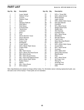
... are not illustrated. 18 Description 1 1 Lower Upright 2 1 Platform Cover 3 1 Console 4 1 Platform Plate 5 1 Base 6 1 Vibration Platform 7 1 Stop Button 8 1 Start Button 9 2 Controller Box 10 1 Transformer 11 1 Controller 12... 1 Motor 13 5 Foot 14 4 Shock Absorber Cover 15 4 Shock Absorber 16 4 Platform Cap 17 1 Power Cord 18 1 Receptacle 19 1 Power Switch 20 2 M10 x 55mm Patch Screw 21 2 Copper Plate...
... are not illustrated. 18 Description 1 1 Lower Upright 2 1 Platform Cover 3 1 Console 4 1 Platform Plate 5 1 Base 6 1 Vibration Platform 7 1 Stop Button 8 1 Start Button 9 2 Controller Box 10 1 Transformer 11 1 Controller 12... 1 Motor 13 5 Foot 14 4 Shock Absorber Cover 15 4 Shock Absorber 16 4 Platform Cap 17 1 Power Cord 18 1 Receptacle 19 1 Power Switch 20 2 M10 x 55mm Patch Screw 21 2 Copper Plate...

