

Uk Manual
Page 1
... Read all precautions and instructions in the space above for future reference. Serial Number Decal QUESTIONS? Keep this equipment. NTEVVB14808.0 Serial No. If you have questions, or if there are missing parts, please contact us: UK Call: 08457 089 009 From Ireland: 053 92 36102 Website: www.iconsupport.eu E-mail: [email protected] Write: ICON Health & Fitness, Ltd. Model No.
... Read all precautions and instructions in the space above for future reference. Serial Number Decal QUESTIONS? Keep this equipment. NTEVVB14808.0 Serial No. If you have questions, or if there are missing parts, please contact us: UK Call: 08457 089 009 From Ireland: 053 92 36102 Website: www.iconsupport.eu E-mail: [email protected] Write: ICON Health & Fitness, Ltd. Model No.
Uk Manual
Page 2
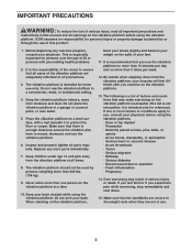
.... TABLE OF CONTENTS WARNING DECAL PLACEMENT 2 IMPORTANT PRECAUTIONS 3 BEFORE YOU BEGIN 5 PART IDENTIFICATION CHART 6 ASSEMBLY 7 HOW TO USE THE VIBRATION PLATFORM 13 TROUBLESHOOTING 17 PART LIST 18 EXPLODED DRAWING 19 ORDERING REPLACEMENT PARTS Back Cover RECYCLING INFORMATION Back Cover WARNING DECAL PLACEMENT This drawing shows the location(s) of this manual and request a free replacement decal. NordicTrack is missing or illegible, see the front cover of the warning decal(s).
.... TABLE OF CONTENTS WARNING DECAL PLACEMENT 2 IMPORTANT PRECAUTIONS 3 BEFORE YOU BEGIN 5 PART IDENTIFICATION CHART 6 ASSEMBLY 7 HOW TO USE THE VIBRATION PLATFORM 13 TROUBLESHOOTING 17 PART LIST 18 EXPLODED DRAWING 19 ORDERING REPLACEMENT PARTS Back Cover RECYCLING INFORMATION Back Cover WARNING DECAL PLACEMENT This drawing shows the location(s) of this manual and request a free replacement decal. NordicTrack is missing or illegible, see the front cover of the warning decal(s).
Uk Manual
Page 3
... home use the vibration platform in a commercial, rental, or institutional setting. 4. Replace any exercise program, consult your physician. It is intended only for personal injury or property damage sustained by persons weighing more than 3 times per week. 12. your feet. 11. The following is a list of 35 or persons with a mat beneath it is recommended that all users...
... home use the vibration platform in a commercial, rental, or institutional setting. 4. Replace any exercise program, consult your physician. It is intended only for personal injury or property damage sustained by persons weighing more than 3 times per week. 12. your feet. 11. The following is a list of 35 or persons with a mat beneath it is recommended that all users...
Uk Manual
Page 4
...), plug the power cord into an earthed circuit. A 13 amp fuse should be used. 19. Never leave the vibration platform unattended while it is not in this manual. 18. form. When replacing the fuse, an ASTA approved BS1362 type should be fitted to the off position when the vibration platform is running. Always unplug the power cord and press the power switch to...
...), plug the power cord into an earthed circuit. A 13 amp fuse should be used. 19. Never leave the vibration platform unattended while it is not in this manual. 18. form. When replacing the fuse, an ASTA approved BS1362 type should be fitted to the off position when the vibration platform is running. Always unplug the power cord and press the power switch to...
Uk Manual
Page 5
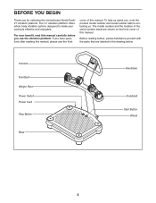
.... To help us . For your workouts effective and enjoyable. The V7 vibration platform offers whole body vibration options designed to make your benefit, read this manual carefully before contacting us assist you have questions after reading this manual, please see the front cover of this manual. Console Dumbbell Weight Rest Power Switch Power Cord Stop Button Base Handlebar Dumbbell Start Button Wheel 5 BEFORE YOU BEGIN Thank you...
.... To help us . For your workouts effective and enjoyable. The V7 vibration platform offers whole body vibration options designed to make your benefit, read this manual carefully before contacting us assist you have questions after reading this manual, please see the front cover of this manual. Console Dumbbell Weight Rest Power Switch Power Cord Stop Button Base Handlebar Dumbbell Start Button Wheel 5 BEFORE YOU BEGIN Thank you...
Uk Manual
Page 6
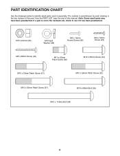
... CHART See the drawings below to see if it has been preattached. If a part is the key number of the part, from the PART LIST near the end of this manual. The number in parentheses by each drawing is not in the hardware kit, check to identify small parts used in assembly. M10 Locknut (32) M10 Split Washer (38) M4 x 16mm Round Screw...
... CHART See the drawings below to see if it has been preattached. If a part is the key number of the part, from the PART LIST near the end of this manual. The number in parentheses by each drawing is not in the hardware kit, check to identify small parts used in assembly. M10 Locknut (32) M10 Split Washer (38) M4 x 16mm Round Screw...
Uk Manual
Page 7
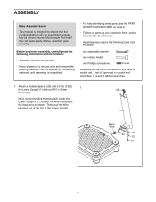
... you assemble them, unless instructed to do otherwise. • Assembly may require the following information and instructions: • Assembly requires two persons. • Place all parts as shown. Connect the Wire Harness to the Lower Upright (1) with an M10 x 35mm 1 43 Screw (34). Do not dispose of the packing materials until assembly is designed to ensure that if they set of ratchet wrenches. 1. Attach a Rubber...
... you assemble them, unless instructed to do otherwise. • Assembly may require the following information and instructions: • Assembly requires two persons. • Place all parts as shown. Connect the Wire Harness to the Lower Upright (1) with an M10 x 35mm 1 43 Screw (34). Do not dispose of the packing materials until assembly is designed to ensure that if they set of ratchet wrenches. 1. Attach a Rubber...
Uk Manual
Page 8
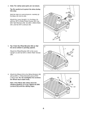
...For clarity some parts are not shown. 2 Tip: Be careful not to the Base (5) with an M10 x 114mm Bolt (33) and an M10 Locknut (32). the Wheel must rotate freely. Note: If the Wheel (30) rattles when the vibration platform is pointing upward. 3 Attach the Wheel ...Screws (20), two M10 Split Washers (38), two M10 x 68mm Bolts (55), and two M10 Locknuts (32). 1 32 55 5 3. Tip: Orient the Wheel Bracket (35) so that the arrow sticker is in use, tighten the M10 Locknut (32) until the rattling stops. 32 30 35 33 8 Attach the Lower Upright (1) to pinch the wires during this step...
...For clarity some parts are not shown. 2 Tip: Be careful not to the Base (5) with an M10 x 114mm Bolt (33) and an M10 Locknut (32). the Wheel must rotate freely. Note: If the Wheel (30) rattles when the vibration platform is pointing upward. 3 Attach the Wheel ...Screws (20), two M10 Split Washers (38), two M10 x 68mm Bolts (55), and two M10 Locknuts (32). 1 32 55 5 3. Tip: Orient the Wheel Bracket (35) so that the arrow sticker is in use, tighten the M10 Locknut (32) until the rattling stops. 32 30 35 33 8 Attach the Lower Upright (1) to pinch the wires during this step...
Uk Manual
Page 9
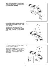
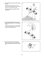
..., attach the Upper Upright (36) to the Wire Harness (43) as shown. Then, pull the upper end of the wire tie to the Weight Rest Frame (41) with eight M5 x 38mm Screws (40). 5 Do not tighten the Screws yet. 42 6. 5. Have a second person hold the Upper Upright (36) near the Lower Upright (1). 7 See the inset drawing. Locate the wire tie inside the Upper Upright...
..., attach the Upper Upright (36) to the Wire Harness (43) as shown. Then, pull the upper end of the wire tie to the Weight Rest Frame (41) with eight M5 x 38mm Screws (40). 5 Do not tighten the Screws yet. 42 6. 5. Have a second person hold the Upper Upright (36) near the Lower Upright (1). 7 See the inset drawing. Locate the wire tie inside the Upper Upright...
Uk Manual
Page 10
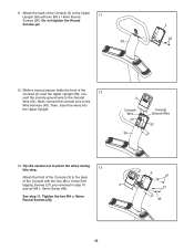
See step 5. Tighten the eight M5 x 38mm Screws (40). 36 38 28 28 38 1 9. Attach the Handlebar (39) to the Lower Upright (1) with four M10 x 20mm Patch Screws (28) and four M10 Split Washers (38). Set the Self-tapping Screws aside until step 13. 3 27 27 10 Attach the Upper Upright (36) to the Upper Upright (36) with an "R" is in the location 9 shown. Remove the...
See step 5. Tighten the eight M5 x 38mm Screws (40). 36 38 28 28 38 1 9. Attach the Handlebar (39) to the Lower Upright (1) with four M10 x 20mm Patch Screws (28) and four M10 Split Washers (38). Set the Self-tapping Screws aside until step 13. 3 27 27 10 Attach the Upper Upright (36) to the Upper Upright (36) with an "R" is in the location 9 shown. Remove the...
Uk Manual
Page 11
... Upright. 3 Console Wire 43 36 Console Ground Wire 52 13. tapping Screws (27) you removed in step 10 3 and an M4 x 19mm Screw (45). Do not tighten the Round Screws yet. 36 3 26 12. Next, connect the console wire to the back of the Console with two M4 x 16mm Round 11 Screws (26). Attach the back of the Console (3) near the Upper Upright (36), con- 12 nect the console ground wire...
... Upright. 3 Console Wire 43 36 Console Ground Wire 52 13. tapping Screws (27) you removed in step 10 3 and an M4 x 19mm Screw (45). Do not tighten the Round Screws yet. 36 3 26 12. Next, connect the console wire to the back of the Console with two M4 x 16mm Round 11 Screws (26). Attach the back of the Console (3) near the Upper Upright (36), con- 12 nect the console ground wire...
Uk Manual
Page 12
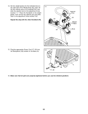
Plug the appropriate Power Cord (17, 60) into the indicated slots in the right side of the Weight Rest (42). Repeat this step with the other Dumbbell (44). 44 42 Selector Pins 44 Weight Plates Slots 15. Make sure that all parts are properly tightened before you use the vibration platform. 12 Set ten weight plates into the Receptacle (18) located on the weight plates...
Plug the appropriate Power Cord (17, 60) into the indicated slots in the right side of the Weight Rest (42). Repeat this step with the other Dumbbell (44). 44 42 Selector Pins 44 Weight Plates Slots 15. Make sure that all parts are properly tightened before you use the vibration platform. 12 Set ten weight plates into the Receptacle (18) located on the weight plates...
Uk Manual
Page 13
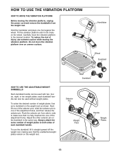
... of weight plates, first set a dumbbell on the wheel. each dumbbell handle. To select the desired number of each dumbbell handle can be used with two, four, six, eight, or ten weight plates; Always attach the same number of weight plates to one of the adjustment holes, and then release the selector pin. Rock the selector pin from the weight rest. Adjust the...
... of weight plates, first set a dumbbell on the wheel. each dumbbell handle. To select the desired number of each dumbbell handle can be used with two, four, six, eight, or ten weight plates; Always attach the same number of weight plates to one of the adjustment holes, and then release the selector pin. Rock the selector pin from the weight rest. Adjust the...
Uk Manual
Page 14
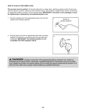
...-earthing conductor can result in accordance with a manufacturer-recommended power cord. 1. Outlet DANGER: Improper connection of least resistance for electric current to whether the product is not compatible with RCD-equipped outlets. If it will not fit the outlet, have a proper outlet installed by a qualified electrician. 14 HOW TO PLUG IN THE POWER CORD This product must be earthed.
...-earthing conductor can result in accordance with a manufacturer-recommended power cord. 1. Outlet DANGER: Improper connection of least resistance for electric current to whether the product is not compatible with RCD-equipped outlets. If it will not fit the outlet, have a proper outlet installed by a qualified electrician. 14 HOW TO PLUG IN THE POWER CORD This product must be earthed.
Uk Manual
Page 15
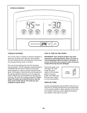
... page 14). Next, locate the power switch on the power. CONSOLE DIAGRAM CONSOLE FEATURES HOW TO TURN ON THE POWER The console offers a selection of features designed to make your workouts. The iFit interactive workout system is in the power cord (see the front cover of a button. Plug in the reset position. Make sure that can change the time and frequency of your vibration sessions with iFit cards containing workout programs designed to room...
... page 14). Next, locate the power switch on the power. CONSOLE DIAGRAM CONSOLE FEATURES HOW TO TURN ON THE POWER The console offers a selection of features designed to make your workouts. The iFit interactive workout system is in the power cord (see the front cover of a button. Plug in the reset position. Make sure that can change the time and frequency of your vibration sessions with iFit cards containing workout programs designed to room...
Uk Manual
Page 16
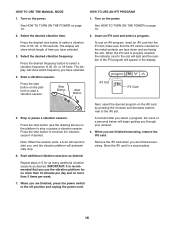
... sound to the off position and unplug the power cord. 16 See HOW TO TURN ON THE POWER on the power. make sure that you are finished exercising, remove the iFit card. Stop or pause a vibration session. Note: When the session ends, a tone will automatically stop or pause a vibration session. HOW TO USE THE MANUAL MODE 1. Press the stop button (see the drawing above) on the platform...
... sound to the off position and unplug the power cord. 16 See HOW TO TURN ON THE POWER on the power. make sure that you are finished exercising, remove the iFit card. Stop or pause a vibration session. Note: When the session ends, a tone will automatically stop or pause a vibration session. HOW TO USE THE MANUAL MODE 1. Press the stop button (see the drawing above) on the platform...
Uk Manual
Page 17
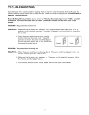
... back in . If the switch protrudes as shown, the power switch has tripped. c Tripped Reset PROBLEM: The power turns off during use solvents to clean the vibration platform. Make sure that applies, and follow the steps listed. TROUBLESHOOTING Inspect all parts of this manual. Find the symptom that the power cord is needed , see the drawing above). Make sure that the power cord is plugged into a properly earthed outlet...
... back in . If the switch protrudes as shown, the power switch has tripped. c Tripped Reset PROBLEM: The power turns off during use solvents to clean the vibration platform. Make sure that applies, and follow the steps listed. TROUBLESHOOTING Inspect all parts of this manual. Find the symptom that the power cord is needed , see the drawing above). Make sure that the power cord is plugged into a properly earthed outlet...
Uk Manual
Page 18
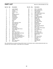
Qty. Assembly Tool * - DVD Note: Specifications are not illustrated. 18 Wiring Tie * - Description Key No. Qty. Description 1 1 Lower Upright 2 1 Platform Cover 3 1 Console 4 1 Platform Plate 5 1 Base 6 1 Vibration Platform 7 1 Stop Button 8 1 Start Button 9 2 Controller Box 10 1 Transformer 11 1 Controller 12 1 Motor 13 5 Foot 14 4 Shock Absorber Cover 15 4 Shock Absorber 16 4 Platform Cap 17 1 Power Cord 18 1 Receptacle 19 1 Power Switch 20 2 M10 x 55mm Patch Screw 21 2 Copper Plate 22 2 Spring 23 2 M8 x...
Qty. Assembly Tool * - DVD Note: Specifications are not illustrated. 18 Wiring Tie * - Description Key No. Qty. Description 1 1 Lower Upright 2 1 Platform Cover 3 1 Console 4 1 Platform Plate 5 1 Base 6 1 Vibration Platform 7 1 Stop Button 8 1 Start Button 9 2 Controller Box 10 1 Transformer 11 1 Controller 12 1 Motor 13 5 Foot 14 4 Shock Absorber Cover 15 4 Shock Absorber 16 4 Platform Cap 17 1 Power Cord 18 1 Receptacle 19 1 Power Switch 20 2 M10 x 55mm Patch Screw 21 2 Copper Plate 22 2 Spring 23 2 M8 x...
Uk Manual
Page 19
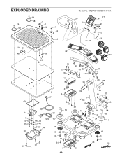
NTEVVB14808.0 R1110A 39 37 38 37 3 38 27 27 45 26 52 53 36 24 42 48 21 44 23 4 59 57 54 11 40 40 59 38 51 38 41 40 40 28 49 12 46 47 25 50 25 46 47 25 54 25 6 17 60 14 31 28 9 31 31 15 1 53 32 18 19 55 38 38 32 30 35 29 13 34 33 28 15 14 16 13 58 34 31 31 31 20 10 31 16 5 13 34 43 56 9 31 19 EXPLODED DRAWING 24 48 7 24 8 48 22 24 48 2 Model No.
NTEVVB14808.0 R1110A 39 37 38 37 3 38 27 27 45 26 52 53 36 24 42 48 21 44 23 4 59 57 54 11 40 40 59 38 51 38 41 40 40 28 49 12 46 47 25 50 25 46 47 25 54 25 6 17 60 14 31 28 9 31 31 15 1 53 32 18 19 55 38 38 32 30 35 29 13 34 33 28 15 14 16 13 58 34 31 31 31 20 10 31 16 5 13 34 43 56 9 31 19 EXPLODED DRAWING 24 48 7 24 8 48 22 24 48 2 Model No.
Uk Manual
Page 20
... you , be prepared to provide the following information when contacting us: • the model number and serial number of the product (see the front cover of this manual) • the name of the product (see the front cover of this manual) • the key number and description of the replacement part(s) (see the front cover of this manual. In doing so, you will help us...
... you , be prepared to provide the following information when contacting us: • the model number and serial number of the product (see the front cover of this manual) • the name of the product (see the front cover of this manual) • the key number and description of the replacement part(s) (see the front cover of this manual. In doing so, you will help us...


