
English Manual
Page 2
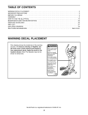
... at actual size. NordicTrack is missing or illegible, see the front cover of this manual and request a free replacement decal. If a decal is a registered trademark of the warning decal(s). Apply the decal in the location shown. TABLE OF CONTENTS WARNING DECAL PLACEMENT 2 IMPORTANT PRECAUTIONS 3 BEFORE YOU BEGIN 4 ASSEMBLY 5 HOW TO USE THE ELLIPTICAL 14 MAINTENANCE AND TROUBLESHOOTING 23 EXERCISE GUIDELINES 25 PART LIST 27 EXPLODED...
... at actual size. NordicTrack is missing or illegible, see the front cover of this manual and request a free replacement decal. If a decal is a registered trademark of the warning decal(s). Apply the decal in the location shown. TABLE OF CONTENTS WARNING DECAL PLACEMENT 2 IMPORTANT PRECAUTIONS 3 BEFORE YOU BEGIN 4 ASSEMBLY 5 HOW TO USE THE ELLIPTICAL 14 MAINTENANCE AND TROUBLESHOOTING 23 EXERCISE GUIDELINES 25 PART LIST 27 EXPLODED...
English Manual
Page 3
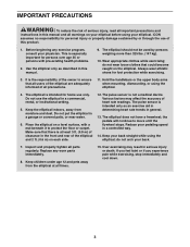
... in the front and rear of heart rate readings. If you feel faint or if you experience pain while exercising, stop immediately and cool down. 3 ICON assumes no responsibility for home use the elliptical in a controlled way. 14. Reduce your back. 7. Before beginning any worn parts immediately. 8. It is not a medical device. The pulse sensor is the responsibility of the owner to ensure that...
... in the front and rear of heart rate readings. If you feel faint or if you experience pain while exercising, stop immediately and cool down. 3 ICON assumes no responsibility for home use the elliptical in a controlled way. 14. Reduce your back. 7. Before beginning any worn parts immediately. 8. It is not a medical device. The pulse sensor is the responsibility of the owner to ensure that...
English Manual
Page 4
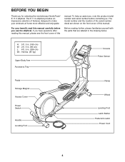
... us . Before reading further, please familiarize yourself with the parts that are shown on the front cover of the serial number decal are labeled in . (206 cm) Wt.: 192 lbs. (87 kg) Upper Body Arm Accessory Tray Console Pulse Sensor Pedal Storage Magnet Access Cover Power Switch Handle Leveling Foot Ramp Wheel Leveling Foot Latch Button Pedal Arm Latch Power Cord 4 BEFORE YOU BEGIN Thank you have questions after reading this manual.
... us . Before reading further, please familiarize yourself with the parts that are shown on the front cover of the serial number decal are labeled in . (206 cm) Wt.: 192 lbs. (87 kg) Upper Body Arm Accessory Tray Console Pulse Sensor Pedal Storage Magnet Access Cover Power Switch Handle Leveling Foot Ramp Wheel Leveling Foot Latch Button Pedal Arm Latch Power Cord 4 BEFORE YOU BEGIN Thank you have questions after reading this manual.

English Manual
Page 5
... needed for assembly. ASSEMBLY Assembly requires two persons. The number in a cleared area and remove the packing materials. Do not dispose of the packing materials until assembly is the key number of the part, from the PART LIST near the end of the elliptical in parentheses below to the included tool(s) and grease packet(s), assembly requires a Phillips screwdriver and a rubber mallet . Place all parts of this manual...
... needed for assembly. ASSEMBLY Assembly requires two persons. The number in a cleared area and remove the packing materials. Do not dispose of the packing materials until assembly is the key number of the part, from the PART LIST near the end of the elliptical in parentheses below to the included tool(s) and grease packet(s), assembly requires a Phillips screwdriver and a rubber mallet . Place all parts of this manual...

English Manual
Page 9
... the right Crank Arm (39). Press the Right Pedal Arm (12) onto the right Pedal Arm Sleeve (46). Tip: Avoid damaging the Large Axle Cover when tightening the Patch Screw. See drawing 8b. Slide the Pedal Arm Sleeve onto the axle on the Right Pedal Arm (12). Repeat this step on the right Crank Arm (39). 7 Orient a Pedal Arm Sleeve (46) so that the Right Pedal Arm latches into place. Apply grease to...
... the right Crank Arm (39). Press the Right Pedal Arm (12) onto the right Pedal Arm Sleeve (46). Tip: Avoid damaging the Large Axle Cover when tightening the Patch Screw. See drawing 8b. Slide the Pedal Arm Sleeve onto the axle on the Right Pedal Arm (12). Repeat this step on the right Crank Arm (39). 7 Orient a Pedal Arm Sleeve (46) so that the Right Pedal Arm latches into place. Apply grease to...

English Manual
Page 14
... TO USE THE ELLIPTICAL HOW TO PLUG IN THE POWER CORD This product must be earthed. If it should malfunction or break down, earthing provides a path of least resistance for electric current to whether the product is damaged, it will not fit the outlet, have a proper outlet installed by ...-if it must be replaced with all local codes and ordinances. Plug the power cord into an appropriate outlet that is properly installed and earthed in doubt as to reduce the risk of the power cord into the receptacle on Elliptical Power Cord DANGER: Improper connection of the equipment-earthing...
... TO USE THE ELLIPTICAL HOW TO PLUG IN THE POWER CORD This product must be earthed. If it should malfunction or break down, earthing provides a path of least resistance for electric current to whether the product is damaged, it will not fit the outlet, have a proper outlet installed by ...-if it must be replaced with all local codes and ordinances. Plug the power cord into an appropriate outlet that is properly installed and earthed in doubt as to reduce the risk of the power cord into the receptacle on Elliptical Power Cord DANGER: Improper connection of the equipment-earthing...
English Manual
Page 15
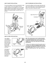
... pedals come to a complete stop. To dismount the elliptical, wait until the flexing motion is in the opposite direction. When the pedals are stationary, step off the lower pedal. 15 Next, stand in the direction shown by the arrow; Leveling Feet If the frame of the elliptical flexes during use , turn the crank arms in front of a second person, carefully move the elliptical to the desired location, and then lower...
... pedals come to a complete stop. To dismount the elliptical, wait until the flexing motion is in the opposite direction. When the pedals are stationary, step off the lower pedal. 15 Next, stand in the direction shown by the arrow; Leveling Feet If the frame of the elliptical flexes during use , turn the crank arms in front of a second person, carefully move the elliptical to the desired location, and then lower...
English Manual
Page 16
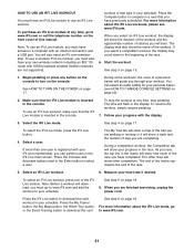
... it guides you to communicate with the touch of a button. When you use the manual mode of the console, you exercise, the console will display continuous exercise feedback. To turn on the power, see page 17. To use the sound system, see page 22. To change the resistance of the pedals and the incline of the ramp with your workouts more effective and enjoyable. While you can change console settings, see...
... it guides you to communicate with the touch of a button. When you use the manual mode of the console, you exercise, the console will display continuous exercise feedback. To turn on the power, see page 17. To use the sound system, see page 22. To change the resistance of the pedals and the incline of the ramp with your workouts more effective and enjoyable. While you can change console settings, see...
English Manual
Page 17
... connected to iFit Live, the manual mode will take a moment for a few seconds each time the incline level changes. 17 Plug in miles or kilometers. Next, locate the power switch on the console. Make sure that you pedal, change the incline, press the Power Adjustable Ramp increase and decrease buttons. Reset Position The display will then light and the console will move upward and downward as desired. To change the resistance of the pedals by pressing the 1 Step Resistance...
... connected to iFit Live, the manual mode will take a moment for a few seconds each time the incline level changes. 17 Plug in miles or kilometers. Next, locate the power switch on the console. Make sure that you pedal, change the incline, press the Power Adjustable Ramp increase and decrease buttons. Reset Position The display will then light and the console will move upward and downward as desired. To change the resistance of the pedals by pressing the 1 Step Resistance...
English Manual
Page 18
... TO CHANGE CONSOLE SETTINGS on the handgrip pulse sensor, remove the plastic. The My Trail tab will also show the number of the workout. As you heart rate using either the handgrip pulse sensor or an optional chest pulse sensor (see step 5). Measure your hands or gripping the contacts tightly. 18 If necessary, press the Home button again. When a wireless iFit Live module is selected, this display mode will show your pedaling speed in the workout...
... TO CHANGE CONSOLE SETTINGS on the handgrip pulse sensor, remove the plastic. The My Trail tab will also show the number of the workout. As you heart rate using either the handgrip pulse sensor or an optional chest pulse sensor (see step 5). Measure your hands or gripping the contacts tightly. 18 If necessary, press the Home button again. When a wireless iFit Live module is selected, this display mode will show your pedaling speed in the workout...
English Manual
Page 19
... are finished exercising, press the power switch to clean the contacts. One resistance level, one ramp incline level, and one target rpm (speed) are finished exercising, unplug the power cord. When you are programmed for the current segment. 19 IMPORTANT: If you do not do not move for several minutes and the buttons are not pressed, the console will turn on the elliptical may be programmed for at...
... are finished exercising, press the power switch to clean the contacts. One resistance level, one ramp incline level, and one target rpm (speed) are finished exercising, unplug the power cord. When you are programmed for the current segment. 19 IMPORTANT: If you do not do not move for several minutes and the buttons are not pressed, the console will turn on the elliptical may be programmed for at...
English Manual
Page 20
... affected. Follow your weight. Make sure to alert you are finished exercising, unplug the power cord. See step 5 on your progress with the display. If a different resistance level, ramp incline level, and/or target rpm is comfortable for a few seconds to pedal at any time, stop the workout at a speed that you burn will appear in the display, increase your pedaling speed does not match...
... affected. Follow your weight. Make sure to alert you are finished exercising, unplug the power cord. See step 5 on your progress with the display. If a different resistance level, ramp incline level, and/or target rpm is comfortable for a few seconds to pedal at any time, stop the workout at a speed that you burn will appear in the display, increase your pedaling speed does not match...
English Manual
Page 21
.... Start the workout. See HOW TO TURN ON THE POWER on page 19. 1. Make sure that the iFit Live module is registered with an internet connection and a USB port. Select an iFit Live workout. 8. workout of this manual. To stop pedaling. To resume the workout, simply resume pedaling. 7. See step 5 on page 19. For more information about the iFit Live mode, go to compete in your personal trainer (see...
.... Start the workout. See HOW TO TURN ON THE POWER on page 19. 1. Make sure that the iFit Live module is registered with an internet connection and a USB port. Select an iFit Live workout. 8. workout of this manual. To stop pedaling. To resume the workout, simply resume pedaling. 7. See step 5 on page 19. For more information about the iFit Live mode, go to compete in your personal trainer (see...
English Manual
Page 22
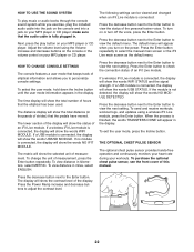
... Enter button. To exit the user mode, press the Incline button. To select the user mode, hold down the Incline button until the user mode information appears in miles, select ENGLISH. To view distance in the display. To send and receive workouts, workout logs, and updates using the Volume increase and decrease buttons on the console or the volume control on the power. THE OPTIONAL CHEST PULSE SENSOR The optional chest pulse sensor provides hands-free operation and continuously monitors your heart rate during...
... Enter button. To exit the user mode, press the Incline button. To select the user mode, hold down the Incline button until the user mode information appears in miles, select ENGLISH. To view distance in the display. To send and receive workouts, workout logs, and updates using the Volume increase and decrease buttons on the console or the volume control on the power. THE OPTIONAL CHEST PULSE SENSOR The optional chest pulse sensor provides hands-free operation and continuously monitors your heart rate during...
English Manual
Page 23
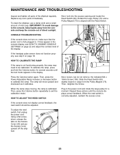
... do not remove, the indicated M4 x 16mm Screw (106). Repeat these actions until the test mode appears in the power cord and rotate the large pulley for a moment. MAINTENANCE AND TROUBLESHOOTING Inspect and tighten all parts of the display. To adjust the reed switch, first unplug the power cord. Next, look into the access opening and locate the Reed Switch (69). Press the Calories button again. When the ramp stops moving, the ramp is calibrated.
... do not remove, the indicated M4 x 16mm Screw (106). Repeat these actions until the test mode appears in the power cord and rotate the large pulley for a moment. MAINTENANCE AND TROUBLESHOOTING Inspect and tighten all parts of the display. To adjust the reed switch, first unplug the power cord. Next, look into the access opening and locate the Reed Switch (69). Press the Calories button again. When the ramp stops moving, the ramp is calibrated.

English Manual
Page 24
... pedal arm, and reattach the access cover. Then, plug in the power cord. Then, remove the M4 x 16mm Round Head Screws (152) and the M4 x 42mm Screws (153) from which holes.) Then, carefully remove the Left Shield. 24 Using a flat screwdriver, release the tabs on the underside of the Left Pedal Arm (13), and then lift the Left Pedal Arm off the elliptical. HOW TO ADJUST THE DRIVE BELT...
... pedal arm, and reattach the access cover. Then, plug in the power cord. Then, remove the M4 x 16mm Round Head Screws (152) and the M4 x 42mm Screws (153) from which holes.) Then, carefully remove the Left Shield. 24 Using a flat screwdriver, release the tabs on the underside of the Left Pedal Arm (13), and then lift the Left Pedal Arm off the elliptical. HOW TO ADJUST THE DRIVE BELT...
English Manual
Page 25
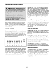
... few minutes of exercise does your body begin to use your heart rate as a guide to 30 minutes with pre-existing health problems. The pulse sensor is intended only as you exercise-never hold your condition, complete three workouts each week, if desired. Cooling Down-Finish with your heart rate near the middle number in preparation for a sustained period of your exercise until your heart rate is to...
... few minutes of exercise does your body begin to use your heart rate as a guide to 30 minutes with pre-existing health problems. The pulse sensor is intended only as you exercise-never hold your condition, complete three workouts each week, if desired. Cooling Down-Finish with your heart rate near the middle number in preparation for a sustained period of your exercise until your heart rate is to...

English Manual
Page 27
... Right Pedal Arm Left Pedal Arm Right Pedal Left Pedal Wheel Cap Disc Right Shield Left Shield Access Cover Right Frame Cover Left Frame Cover Double Tree Fastener Front Upright Cover Rear Upright Cover Accessory Tray Top Cover Pedal Arm Cap Mount w/Screw Magnet Cover Pedal Arm Magnet Pedal Arm Roller Console Pulse Sensor/Wire Handgrip Wheel Stabilizer Cap Drive Belt Crank Arm Hairpin Cotter Pin Leveling Foot Latch Bracket Right Link Arm Lift Bracket Lift Axle Bushing Pedal Arm Sleeve Inner Sleeve Bushing Upright Axle Latch Housing Latch Model No...
... Right Pedal Arm Left Pedal Arm Right Pedal Left Pedal Wheel Cap Disc Right Shield Left Shield Access Cover Right Frame Cover Left Frame Cover Double Tree Fastener Front Upright Cover Rear Upright Cover Accessory Tray Top Cover Pedal Arm Cap Mount w/Screw Magnet Cover Pedal Arm Magnet Pedal Arm Roller Console Pulse Sensor/Wire Handgrip Wheel Stabilizer Cap Drive Belt Crank Arm Hairpin Cotter Pin Leveling Foot Latch Bracket Right Link Arm Lift Bracket Lift Axle Bushing Pedal Arm Sleeve Inner Sleeve Bushing Upright Axle Latch Housing Latch Model No...

English Manual
Page 28
... Screw Frame Wire Ground Wire M8 x 35mm Patch Screw M8 x 38mm Screw Left Pedal Insert M4 x 16mm Round Head Screw M4 x 42mm Screw M4 x 8mm Screw Large Pedal Arm Snap Ring M4 x 19mm Screw Right Pedal Insert Adjustment Nut Blue Wire White Wire Userʼs Manual Assembly Tool Grease Packet Note: Specifications are not illustrated. 28 For information about ordering replacement parts, see the back cover of this manual. *These parts are subject to change without notice. Description Key...
... Screw Frame Wire Ground Wire M8 x 35mm Patch Screw M8 x 38mm Screw Left Pedal Insert M4 x 16mm Round Head Screw M4 x 42mm Screw M4 x 8mm Screw Large Pedal Arm Snap Ring M4 x 19mm Screw Right Pedal Insert Adjustment Nut Blue Wire White Wire Userʼs Manual Assembly Tool Grease Packet Note: Specifications are not illustrated. 28 For information about ordering replacement parts, see the back cover of this manual. *These parts are subject to change without notice. Description Key...
English Manual
Page 32
... key number and description of the replacement part(s) (see the front cover of this manual. To preserve the environment, this product must not be disposed of in China © 2011 ICON IP, Inc. ORDERING REPLACEMENT PARTS To order replacement parts, see the PART LIST and the EXPLODED DRAWING near the end of this manual) RECYCLING INFORMATION This electronic product must be recycled after its useful life...
... key number and description of the replacement part(s) (see the front cover of this manual. To preserve the environment, this product must not be disposed of in China © 2011 ICON IP, Inc. ORDERING REPLACEMENT PARTS To order replacement parts, see the PART LIST and the EXPLODED DRAWING near the end of this manual) RECYCLING INFORMATION This electronic product must be recycled after its useful life...


