Hardware Installation Guide
Page 3
... Installation Package Contents 13 Protecting against Electrostatic Discharge 13 Unpack the Hardware 14 Installation 14 Select a Location 15 Install the Switch 16 Install the M4100-D12G or M4100-D10-PoE Using Magnets 19 Check the Installation 20 Connect to Power and Check the LEDs 20 SFP Modules 21 Connect Equipment to the Switch 22...
... Installation Package Contents 13 Protecting against Electrostatic Discharge 13 Unpack the Hardware 14 Installation 14 Select a Location 15 Install the Switch 16 Install the M4100-D12G or M4100-D10-PoE Using Magnets 19 Check the Installation 20 Connect to Power and Check the LEDs 20 SFP Modules 21 Connect Equipment to the Switch 22...

Hardware Installation Guide
Page 4
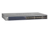
... switch, and USB console port. 4 Front Panels and LEDs The following : M4100-26G M4100-50G M4100-26-POE M4100-26G-POE M4100-50G-POE+ M4100-50-POE M4100-D10-POE M4100-D12G M4100-12GF M4100-D12G-POE+ M4100-24G-POE+ M4100-12G-POE+ This guide describes hardware installation and basic troubleshooting for each product, visit the NETGEAR website at http://www.netgear.com. The M4100 Series switches include the following figures show the front panels of...
... switch, and USB console port. 4 Front Panels and LEDs The following : M4100-26G M4100-50G M4100-26-POE M4100-26G-POE M4100-50G-POE+ M4100-50-POE M4100-D10-POE M4100-D12G M4100-12GF M4100-D12G-POE+ M4100-24G-POE+ M4100-12G-POE+ This guide describes hardware installation and basic troubleshooting for each product, visit the NETGEAR website at http://www.netgear.com. The M4100 Series switches include the following figures show the front panels of...

Hardware Installation Guide
Page 10
...NETGEAR Managed Switch Console switch Console ports Lock Power adapter connector Figure 14. M4100-D12G-POE+ rear panel AC power connector Safety Instructions Use the following safety guidelines to ensure your own personal safety and to the equipment, observe the following precautions. • Observe and follow service markings. - M4100-D10-POE and M4100...-D12G rear panels Console port RPS Lock power supply connector Figure 15. M4100-12GF, 24G-POE+, 12G-POE+ rear panel AC power connector Lock Console ...
...NETGEAR Managed Switch Console switch Console ports Lock Power adapter connector Figure 14. M4100-D12G-POE+ rear panel AC power connector Safety Instructions Use the following safety guidelines to ensure your own personal safety and to the equipment, observe the following precautions. • Observe and follow service markings. - M4100-D10-POE and M4100...-D12G rear panels Console port RPS Lock power supply connector Figure 15. M4100-12GF, 24G-POE+, 12G-POE+ rear panel AC power connector Lock Console ...

Hardware Installation Guide
Page 13
... Installation 2 This chapter explains how to install the hardware for the SFP sockets • Rack-mounting kit • Wall-mounting kit (M4100-D10-POE, M4100-D12G, and M4100-D12G-POE+ only) • Magnetic mounting kit (M4100-D10-POE and M4100-D12G only) • USB console cable with one mini B connector and one type A connector • Resource CD: The CD includes...
... Installation 2 This chapter explains how to install the hardware for the SFP sockets • Rack-mounting kit • Wall-mounting kit (M4100-D10-POE, M4100-D12G, and M4100-D12G-POE+ only) • Magnetic mounting kit (M4100-D10-POE and M4100-D12G only) • USB console cable with one mini B connector and one type A connector • Resource CD: The CD includes...

Hardware Installation Guide
Page 16
.... The rubber footpads cushion the switch against shock and vibrations. Mount the equipment into a rack so that any possible overloading of power strips). • Clearance. NETGEAR Managed Switch Install the Switch You can install the switch on a Flat Surface The switch ships with the maximum rated ambient temperature. • Reduced airflow... the following considerations in mind as you install your switch in the back of the room. Therefore, consider installing the equipment in a Rack Note: The M4100-D10-PoE, M4100-D12G, and M4100-D12G-POE+ are not rack mountable.
.... The rubber footpads cushion the switch against shock and vibrations. Mount the equipment into a rack so that any possible overloading of power strips). • Clearance. NETGEAR Managed Switch Install the Switch You can install the switch on a Flat Surface The switch ships with the maximum rated ambient temperature. • Reduced airflow... the following considerations in mind as you install your switch in the back of the room. Therefore, consider installing the equipment in a Rack Note: The M4100-D10-PoE, M4100-D12G, and M4100-D12G-POE+ are not rack mountable.
Hardware Installation Guide
Page 18
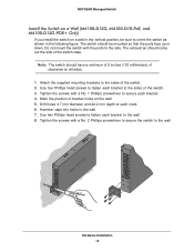
... Phillips head screws to the wall. Mark the position of the switch. 3. Hammer caps into holes in the following figure. NETGEAR Managed Switch Install the Switch on a Wall (M4100-D12G, M4100-D10-PoE, and M4100-D12G-POE+ Only) If you install the switch on a wall in the vertical position, be mounted so that the ports face up...
... Phillips head screws to the wall. Mark the position of the switch. 3. Hammer caps into holes in the following figure. NETGEAR Managed Switch Install the Switch on a Wall (M4100-D12G, M4100-D10-PoE, and M4100-D12G-POE+ Only) If you install the switch on a wall in the vertical position, be mounted so that the ports face up...
Hardware Installation Guide
Page 19
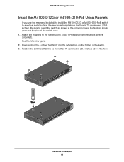
... (29.5 inches). Attach the magnets to orient the switch as shown in the following figure. 2. NETGEAR Managed Switch Install the M4100-D12G or M4100-D10-PoE Using Magnets If you use the magnets (included) to install the M4100-D12G or M4100-D10-PoE switch to a vertical metal surface, the maximum height above the floor is no more than 75...
... (29.5 inches). Attach the magnets to orient the switch as shown in the following figure. 2. NETGEAR Managed Switch Install the M4100-D12G or M4100-D10-PoE Using Magnets If you use the magnets (included) to install the M4100-D12G or M4100-D10-PoE switch to a vertical metal surface, the maximum height above the floor is no more than 75...

Hardware Installation Guide
Page 20
...NETGEAR Managed Switch Check the Installation Before you connect the power cord, select an AC outlet that is not controlled by a wall switch (which can turn off switch. Verify that cables are not damaged and will get power from an RPS. Note: The M4100-26G, 50G, 26-PoE, 26G-PoE, 50-PoE+, 50G-PoE, 12GF, 24G-POE+, 12G-POE... theses switches might not operate correctly. 3. Inspect the equipment thoroughly. 2. Connect one end of the AC power adapter cable (M4100-DG12 or M4100-D10-PoE) or the AC power cord to the rear of these switches for system operation. Connect port 1 of the switch, and ...
...NETGEAR Managed Switch Check the Installation Before you connect the power cord, select an AC outlet that is not controlled by a wall switch (which can turn off switch. Verify that cables are not damaged and will get power from an RPS. Note: The M4100-26G, 50G, 26-PoE, 26G-PoE, 50-PoE+, 50G-PoE, 12GF, 24G-POE+, 12G-POE... theses switches might not operate correctly. 3. Inspect the equipment thoroughly. 2. Connect one end of the AC power adapter cable (M4100-DG12 or M4100-D10-PoE) or the AC power cord to the rear of these switches for system operation. Connect port 1 of the switch, and ...

Hardware Installation Guide
Page 28
Fast Ethernet switches physical specifications Fast Ethernet Switches M4100-26-POE (FSM7226P) M4100-50-POE (FSM7250P) M4100-D10-POE (FSM5210P) Interface (AutoUplink on all RJ-45 ports) 24 RJ-45 ports for 10/100 ...2 SFP ports for 100/1000 Mbps 2 SFP ports for 100/1000 Mbps 2 SFP ports for 100/1000 Mbps 24 PoE ports 48 IEEE802.3af PoE 8 IEEE802.3af PoE 1 USB type A connector ports ports RS-232 console port 1 USB type A connector 1 USB type A connector 1...power consumption (W) (100-240V AC, 50-60 Hz) 456.29 486.64 87.30 Technical Specifications 28 NETGEAR Managed Switch Table 6.
Fast Ethernet switches physical specifications Fast Ethernet Switches M4100-26-POE (FSM7226P) M4100-50-POE (FSM7250P) M4100-D10-POE (FSM5210P) Interface (AutoUplink on all RJ-45 ports) 24 RJ-45 ports for 10/100 ...2 SFP ports for 100/1000 Mbps 2 SFP ports for 100/1000 Mbps 2 SFP ports for 100/1000 Mbps 24 PoE ports 48 IEEE802.3af PoE 8 IEEE802.3af PoE 1 USB type A connector ports ports RS-232 console port 1 USB type A connector 1 USB type A connector 1...power consumption (W) (100-240V AC, 50-60 Hz) 456.29 486.64 87.30 Technical Specifications 28 NETGEAR Managed Switch Table 6.
CLI Manual
Page 1
ProSafe Managed Switch Command Line Interface (CLI) User Manual 350 East Plumeria Drive San Jose, CA 95134 USA February 2013 202-11166-02 1.0 10.0.1 M7100-24X M4100-24G-POE+ M4100-26G M4100-26-POE M4100-26G-POE M4100-50G M4100-50-POE M4100-50G-POE+ M4100-12GF M4100-12G-POE+ M4100-D12G M4100-D10-POE M4100-D12G-POE+
ProSafe Managed Switch Command Line Interface (CLI) User Manual 350 East Plumeria Drive San Jose, CA 95134 USA February 2013 202-11166-02 1.0 10.0.1 M7100-24X M4100-24G-POE+ M4100-26G M4100-26-POE M4100-26G-POE M4100-50G M4100-50-POE M4100-50G-POE+ M4100-12GF M4100-12G-POE+ M4100-D12G M4100-D10-POE M4100-D12G-POE+
CLI Manual
Page 734
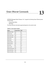
... Model Energy-Detect EEE M4100-D10-POE Yes No M4100-D12G Yes Yes M4100-50G-POE+ Yes Yes M4100-26G-POE Yes Yes M4100-50G Yes Yes M4100-26G Yes Yes M4100-50-POE Yes No M4100-26-POE Yes No M7100-24x No Yes M4100-12GF Yes No M4100-D12G-POE+ Yes No M4100-24G-POE+ Yes No M4100-12G-POE+ Yes No 734 Green Ethernet Commands 13 NETGEAR Managed Switch Release 10...
... Model Energy-Detect EEE M4100-D10-POE Yes No M4100-D12G Yes Yes M4100-50G-POE+ Yes Yes M4100-26G-POE Yes Yes M4100-50G Yes Yes M4100-26G Yes Yes M4100-50-POE Yes No M4100-26-POE Yes No M7100-24x No Yes M4100-12GF Yes No M4100-D12G-POE+ Yes No M4100-24G-POE+ Yes No M4100-12G-POE+ Yes No 734 Green Ethernet Commands 13 NETGEAR Managed Switch Release 10...

