Hardware Installation Guide
Page 3
... Installation Package Contents 13 Protecting against Electrostatic Discharge 13 Unpack the Hardware 14 Installation 14 Select a Location 15 Install the Switch 16 Install the M4100-D12G or M4100-D10-PoE Using Magnets 19 Check the Installation 20 Connect to Power and Check the LEDs 20 SFP Modules 21 Connect Equipment to the Switch 22...
... Installation Package Contents 13 Protecting against Electrostatic Discharge 13 Unpack the Hardware 14 Installation 14 Select a Location 15 Install the Switch 16 Install the M4100-D12G or M4100-D10-PoE Using Magnets 19 Check the Installation 20 Connect to Power and Check the LEDs 20 SFP Modules 21 Connect Equipment to the Switch 22...

Hardware Installation Guide
Page 4
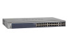
... ports, and USB console selection slide switch, and USB console port. 4 For information about features for these managed switches. Front Panels and LEDs The following : M4100-26G M4100-50G M4100-26-POE M4100-26G-POE M4100-50G-POE+ M4100-50-POE M4100-D10-POE M4100-D12G M4100-12GF M4100-D12G-POE+ M4100-24G-POE+ M4100-12G-POE+ This guide describes hardware installation and basic troubleshooting for each product, visit the NETGEAR website at http://www...
... ports, and USB console selection slide switch, and USB console port. 4 For information about features for these managed switches. Front Panels and LEDs The following : M4100-26G M4100-50G M4100-26-POE M4100-26G-POE M4100-50G-POE+ M4100-50-POE M4100-D10-POE M4100-D12G M4100-12GF M4100-D12G-POE+ M4100-24G-POE+ M4100-12G-POE+ This guide describes hardware installation and basic troubleshooting for each product, visit the NETGEAR website at http://www...

Hardware Installation Guide
Page 7
NETGEAR Managed Switch Power Fan PD MaxPoE Reset USB PoE (Max 30W per port): OFF = No PD Green = PoE Powered Yellow = PoE Fault PoE SPD/Link/ACT Link/ACT mode: Green = Link at 1G Yellow = Link at 10/100M Blink = ACT SPF Link/Act mode: Green = Link at 1G ... prt Power Fan PD MaxPoE Reset USB LEDs USB port Reset button Figure 11. M4100-D12G-POE+ front panel M4100-D12G-POE+ SFP SPD/Link/ACT mode Green = Link at 1G Yellow = Link at 100M Blink = ACT USB DB9 Console(USB) 115200,N,8,1 POE ports Console Mini switch SFP ports USB port Power Fan PD MaxPoE Reset USB...
NETGEAR Managed Switch Power Fan PD MaxPoE Reset USB PoE (Max 30W per port): OFF = No PD Green = PoE Powered Yellow = PoE Fault PoE SPD/Link/ACT Link/ACT mode: Green = Link at 1G Yellow = Link at 10/100M Blink = ACT SPF Link/Act mode: Green = Link at 1G ... prt Power Fan PD MaxPoE Reset USB LEDs USB port Reset button Figure 11. M4100-D12G-POE+ front panel M4100-D12G-POE+ SFP SPD/Link/ACT mode Green = Link at 1G Yellow = Link at 100M Blink = ACT USB DB9 Console(USB) 115200,N,8,1 POE ports Console Mini switch SFP ports USB port Power Fan PD MaxPoE Reset USB...

Hardware Installation Guide
Page 8
...'s classification - Blinking yellow: Power module is providing power to PSE. Solid green: The PoE powered device (PD) is connected and the port is not connected to the switch. NETGEAR Managed Switch Table 1. Off: PD port 1 is supplying power successfully. Solid green: A...is connected to PSE getting 802.3at specified power. Note: Only for M4100-D12G, -24G-POE, D12G-POE, 12G-POE+, -12GF Solid yellow: Indicates less than 7 watts of PoE power available for M4100-26G, 50G, 26-POE, 26G-POE, 50G-POE+, and 50-POE Solid green: PD port 1 is connected to PSE getting 802.3af ...
...'s classification - Blinking yellow: Power module is providing power to PSE. Solid green: The PoE powered device (PD) is connected and the port is not connected to the switch. NETGEAR Managed Switch Table 1. Off: PD port 1 is supplying power successfully. Solid green: A...is connected to PSE getting 802.3at specified power. Note: Only for M4100-D12G, -24G-POE, D12G-POE, 12G-POE+, -12GF Solid yellow: Indicates less than 7 watts of PoE power available for M4100-26G, 50G, 26-POE, 26G-POE, 50G-POE+, and 50-POE Solid green: PD port 1 is connected to PSE getting 802.3af ...

Hardware Installation Guide
Page 9
...port (only for M4100-26G, 50G, 26-POE, 26G-POE, 50G-POE+, 50-POE, D12-PoE, and D12G), a redundant power supply connector (only for M4100-26G, 50G, 26-POE, 26G-POE, 50G-POE+, 50-POE, 12GF, 24G-POE+, and 12G-POE+), and a standard AC power receptacle for the supplied power cord. NETGEAR Managed Switch Table 1. PoE-PD Off: No ... the port. Mini USB port Console port RPS power supply connector Lock AC power connector Figure 13. M4100-26G, 50G, 26-POE, 26G-POE, 50G-POE+, and 50-POE rear panels 9 LED descriptions (Continued) LED Link/ACT (RJ45 port) SPD (RJ45 port) Description ...
...port (only for M4100-26G, 50G, 26-POE, 26G-POE, 50G-POE+, 50-POE, D12-PoE, and D12G), a redundant power supply connector (only for M4100-26G, 50G, 26-POE, 26G-POE, 50G-POE+, 50-POE, 12GF, 24G-POE+, and 12G-POE+), and a standard AC power receptacle for the supplied power cord. NETGEAR Managed Switch Table 1. PoE-PD Off: No ... the port. Mini USB port Console port RPS power supply connector Lock AC power connector Figure 13. M4100-26G, 50G, 26-POE, 26G-POE, 50G-POE+, and 50-POE rear panels 9 LED descriptions (Continued) LED Link/ACT (RJ45 port) SPD (RJ45 port) Description ...

Hardware Installation Guide
Page 10
... in your system from potential damage. NETGEAR Managed Switch Console switch Console ports Lock Power adapter connector Figure 14. M4100-12GF, 24G-POE+, 12G-POE+ rear panel AC power connector Lock Console port Figure 16. M4100-D10-POE and M4100-D12G rear panels Console port RPS Lock power supply connector Figure 15. M4100-D12G-POE+ rear panel AC power connector Safety...
... in your system from potential damage. NETGEAR Managed Switch Console switch Console ports Lock Power adapter connector Figure 14. M4100-12GF, 24G-POE+, 12G-POE+ rear panel AC power connector Lock Console port Figure 16. M4100-D10-POE and M4100-D12G rear panels Console port RPS Lock power supply connector Figure 15. M4100-D12G-POE+ rear panel AC power connector Safety...

Hardware Installation Guide
Page 13
... either these documents or links to install the hardware for the SFP sockets • Rack-mounting kit • Wall-mounting kit (M4100-D10-POE, M4100-D12G, and M4100-D12G-POE+ only) • Magnetic mounting kit (M4100-D10-POE and M4100-D12G only) • USB console cable with preinstalled software • Power cord • Rubber footpads for tabletop installation • Rubber caps...
... either these documents or links to install the hardware for the SFP sockets • Rack-mounting kit • Wall-mounting kit (M4100-D10-POE, M4100-D12G, and M4100-D12G-POE+ only) • Magnetic mounting kit (M4100-D10-POE and M4100-D12G only) • USB console cable with preinstalled software • Power cord • Rubber footpads for tabletop installation • Rubber caps...

Hardware Installation Guide
Page 16
... when addressing this , ground the rack itself. To ensure this concern. • Reliable grounding. To install your switch in a Rack Note: The M4100-D10-PoE, M4100-D12G, and M4100-D12G-POE+ are not rack mountable. NETGEAR Managed Switch Install the Switch You can install the switch on the bottom of the switch. This product requires reliable grounding to...
... when addressing this , ground the rack itself. To ensure this concern. • Reliable grounding. To install your switch in a Rack Note: The M4100-D10-PoE, M4100-D12G, and M4100-D12G-POE+ are not rack mountable. NETGEAR Managed Switch Install the Switch You can install the switch on the bottom of the switch. This product requires reliable grounding to...
Hardware Installation Guide
Page 18
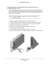
... the position of the switch case. Note: The switch should come out the side of bracket holes on the wall. 5. NETGEAR Managed Switch Install the Switch on a Wall (M4100-D12G, M4100-D10-PoE, and M4100-D12G-POE+ Only) If you install the switch on a wall in the vertical position, be mounted so that the ports face up or...
... the position of the switch case. Note: The switch should come out the side of bracket holes on the wall. 5. NETGEAR Managed Switch Install the Switch on a Wall (M4100-D12G, M4100-D10-PoE, and M4100-D12G-POE+ Only) If you install the switch on a wall in the vertical position, be mounted so that the ports face up or...
Hardware Installation Guide
Page 19
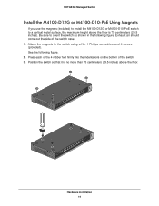
... should come out the side of the switch. 3. See the following figure. Hardware Installation 19 NETGEAR Managed Switch Install the M4100-D12G or M4100-D10-PoE Using Magnets If you use the magnets (included) to install the M4100-D12G or M4100-D10-PoE switch to a vertical metal surface, the maximum height above the floor is no more than 75...
... should come out the side of the switch. 3. See the following figure. Hardware Installation 19 NETGEAR Managed Switch Install the M4100-D12G or M4100-D10-PoE Using Magnets If you use the magnets (included) to install the M4100-D12G or M4100-D10-PoE switch to a vertical metal surface, the maximum height above the floor is no more than 75...

Hardware Installation Guide
Page 20
... the switch. Note: The M4100-26G, 50G, 26-PoE, 26G-PoE, 50-PoE+, 50G-PoE, 12GF, 24G-POE+, 12G-POE+ can also obtain power from a PSE (power sourcing equipment) switch if AC power is not available. The PSE device should light in the following checks: 1. NETGEAR Managed Switch Check the Installation Before... you connect the power cord, select an AC outlet that is not controlled by a wall switch (which can turn off switch. Note: Normally the M4100-D12G and M4100-D12G-POE+ will not create a safety hazard....
... the switch. Note: The M4100-26G, 50G, 26-PoE, 26G-PoE, 50-PoE+, 50G-PoE, 12GF, 24G-POE+, 12G-POE+ can also obtain power from a PSE (power sourcing equipment) switch if AC power is not available. The PSE device should light in the following checks: 1. NETGEAR Managed Switch Check the Installation Before... you connect the power cord, select an AC outlet that is not controlled by a wall switch (which can turn off switch. Note: Normally the M4100-D12G and M4100-D12G-POE+ will not create a safety hazard....

Hardware Installation Guide
Page 21
...modules (sold separately) can be inserted directly into the switch port. 2. For more information, see Troubleshooting on the front panel of the M4100-D12G and M4100-D12G-POE+ blinks green, port 1 is good. Press firmly to make sure that the module seats into the switch port: 1. Note: Use ...only optical transceiver modules that are UL approved and that the power source is connected to a IEEE802.3af PoE device. NETGEAR Managed Switch • If ...
...modules (sold separately) can be inserted directly into the switch port. 2. For more information, see Troubleshooting on the front panel of the M4100-D12G and M4100-D12G-POE+ blinks green, port 1 is good. Press firmly to make sure that the module seats into the switch port: 1. Note: Use ...only optical transceiver modules that are UL approved and that the power source is connected to a IEEE802.3af PoE device. NETGEAR Managed Switch • If ...
Hardware Installation Guide
Page 26
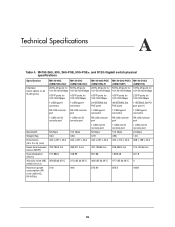
... switch physical specifications Specification Interface (Auto Uplink on all RJ-45 ports) M4100-26G M4100-50G M4100-26G-POE M4100-50G-POE+ M4100-D12G (GSM7224v2h2) (GSM7248v2h2) (GSM7226LP) (GSM7248P) (GSM5212) 26 RJ-45 ports for 50 RJ-45 ports, 26 RJ-45 ports for 50 RJ-45 ports for .../1000 Mbps 4 SFP ports for 100/1000 Mbps 2 SFP ports for 100/1000 Mbps 1 USB type A connector 1 USB type A connector 24 IEEE802.3at PoE ports 48 IEEE802.3at PoE ports 1 IEEE802.3at PD port (port 1) RS-232 console port RS-232 console port 1 USB type A connector 1 USB type A connector 1 USB type A...
... switch physical specifications Specification Interface (Auto Uplink on all RJ-45 ports) M4100-26G M4100-50G M4100-26G-POE M4100-50G-POE+ M4100-D12G (GSM7224v2h2) (GSM7248v2h2) (GSM7226LP) (GSM7248P) (GSM5212) 26 RJ-45 ports for 50 RJ-45 ports, 26 RJ-45 ports for 50 RJ-45 ports for .../1000 Mbps 4 SFP ports for 100/1000 Mbps 2 SFP ports for 100/1000 Mbps 1 USB type A connector 1 USB type A connector 24 IEEE802.3at PoE ports 48 IEEE802.3at PoE ports 1 IEEE802.3at PD port (port 1) RS-232 console port RS-232 console port 1 USB type A connector 1 USB type A connector 1 USB type A...
Hardware Installation Guide
Page 27
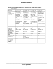
... 1 USB Type A connector RS-232 console port 1 USB mini B console port 48 Gbps 4.368 440 x 257 x 43.2 M4100-D12G-POE+ M4100-12G-POE+ (GSM5212P) (GSM7212P) M4100-12GF (GSM7212F) 12 RJ-45 ports for 10/100/1000 Mbps 12 RJ-45 ports for 10/100/1000 Mbps 2 SFP ports for 100/1000 ....00 49.9 553.00 35.1 dB @ 25dC with AC mode 0dB with PD mode 167.00 50.3 452.00 48 161.00 Technical Specifications 27 NETGEAR Managed Switch Table 5.
... 1 USB Type A connector RS-232 console port 1 USB mini B console port 48 Gbps 4.368 440 x 257 x 43.2 M4100-D12G-POE+ M4100-12G-POE+ (GSM5212P) (GSM7212P) M4100-12GF (GSM7212F) 12 RJ-45 ports for 10/100/1000 Mbps 12 RJ-45 ports for 10/100/1000 Mbps 2 SFP ports for 100/1000 ....00 49.9 553.00 35.1 dB @ 25dC with AC mode 0dB with PD mode 167.00 50.3 452.00 48 161.00 Technical Specifications 27 NETGEAR Managed Switch Table 5.
CLI Manual
Page 1
ProSafe Managed Switch Command Line Interface (CLI) User Manual 350 East Plumeria Drive San Jose, CA 95134 USA February 2013 202-11166-02 1.0 10.0.1 M7100-24X M4100-24G-POE+ M4100-26G M4100-26-POE M4100-26G-POE M4100-50G M4100-50-POE M4100-50G-POE+ M4100-12GF M4100-12G-POE+ M4100-D12G M4100-D10-POE M4100-D12G-POE+
ProSafe Managed Switch Command Line Interface (CLI) User Manual 350 East Plumeria Drive San Jose, CA 95134 USA February 2013 202-11166-02 1.0 10.0.1 M7100-24X M4100-24G-POE+ M4100-26G M4100-26-POE M4100-26G-POE M4100-50G M4100-50-POE M4100-50G-POE+ M4100-12GF M4100-12G-POE+ M4100-D12G M4100-D10-POE M4100-D12G-POE+
CLI Manual
Page 734
... 13 NETGEAR Managed Switch Release 10.0.1 supports the following Green Ethernet power saving modes: • Energy Detect Mode • EEE Mode The Green Ethernet commands supported depends on the switch model Table 56. Green feature support Model Energy-Detect EEE M4100-D10-POE Yes No M4100-D12G Yes Yes M4100-50G-POE+ Yes Yes M4100-26G-POE Yes Yes M4100-50G...
... 13 NETGEAR Managed Switch Release 10.0.1 supports the following Green Ethernet power saving modes: • Energy Detect Mode • EEE Mode The Green Ethernet commands supported depends on the switch model Table 56. Green feature support Model Energy-Detect EEE M4100-D10-POE Yes No M4100-D12G Yes Yes M4100-50G-POE+ Yes Yes M4100-26G-POE Yes Yes M4100-50G...

